Jegs 89504 User manual

Installation Instructions for 89504
Fully Automatic AM/FM Power Antenna
Includes 6 Mounting Bases
This antenna is designed for optimum performance for either AM or FM bands. The antenna is raised or lowered by
operating the radio on/off switch.
Prior to installing the antenna, read the entire installation instructions.
May require an extension cable depending on vehicle or an antenna adapter cable for many 1995-up Ford, 1988-up
GM and some imports.
1. REPLACEMENT OF EXISTING POWER ANTENNA, REMOVING OLD ANTENNA.
A) Gain access to the underside of the fender area through the trunk, fender splash panel, etc.
B) Remove mounting bracket, drain tube, electrical wire and antenna coaxial cable. When removing electrical wires and
coaxial cable from the antenna, follow to the closest connector and disconnect.
DO NOT CUT COAXIAL CABLE.
C) Disassemble the mounting base and save the parts, they may be used with the installation of the new antenna.
D) Remove old antenna from below fender.
E) To avoid cutting car wiring, you may want to cut the connector off of the old antenna removed from the car, attaching
the new antenna wiring to the old connector wires and directly plug into car wiring.
2. NEW ANTENNA INSTALLATION:
For first time antenna installations:
A) Use original factory hole or select a location on the front or back fender of car for mounting antenna. In selecting the
location, make sure the underside of the fender is free of any obstruction such as weld beads, braces, gussets and sub-
fender. Also, be sure that sufficient clearance is available under fender to house the antenna, approximately 11-1/2” /
29cm.
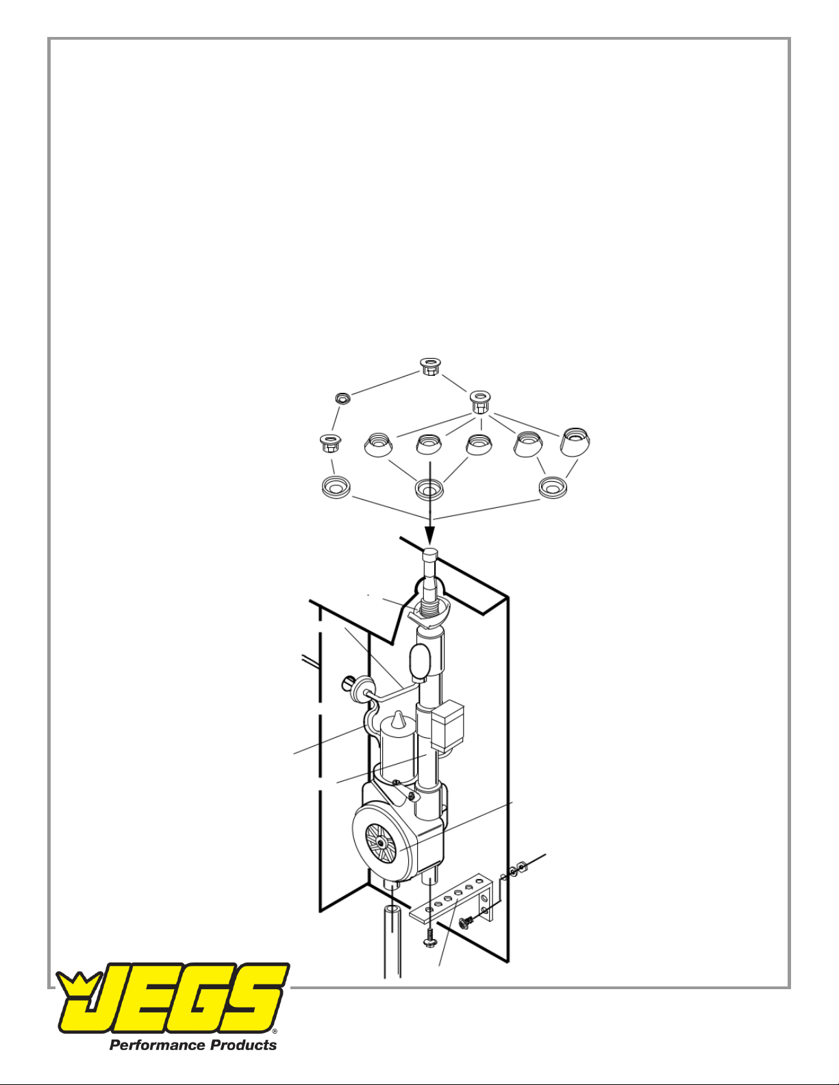
B) Six mounting bases are provided with the antenna. Five fixed angle and one adjustable angle flush mount base.
(See Figure 1).
C) Remove the installed flush mounting base from new antenna. Select the proper base with correct angle for fender
(as shown in figure 1) or reuse original mounting base previously removed from old antenna. NOTE: The five fixed
angle bases require a 7/8” /22mm hole. The adjustable angle flush base requires a 1” 25mm hole.
D) A 1/8” / 3mm pilot hole should be drilled, then enlarged with a hole saw or drill bit to the proper size.
E) Remove all burrs, paint, road dirt or undercoating from around the underside of the hole.
F) Install the antenna from the underside of the fender and assemble the base above the fender according to Figure 1.
BE SURE THE RETAINER RESTS EVENLY ON THE UNDERSIDE OF THE FENDER TO ALLEVIATE ANY
POSSIBLE DAMAGE TO THE VEHICLE. Align the mast vertically by slightly tightening the antenna mounting nut while
adjusting the mast to be vertical.
1-800-345-4545 jegs.com
G) To prevent movement and maintain the desired angle, secure the bottom of the motor assembly with the supplied
perforated strap. Holes are provided with the strap to accommodate various mounting positions. It may be necessary to
bend the strap to conform to the fit of the antenna and car. Be sure the antenna retainer is grounded to the underside of
the fender and the black ground wire is grounded properly to the vehicle chassis. If the retainer and ground wire are not
properly grounded, THE ANTENNA WILL NOT FUNCTION.
H) With the bottom of the antenna motor assembly secured, the mast at the desired angle and the retainer resting
evenly on the underside of the fender, tighten the mounting nut firmly to secure the entire antenna assembly. Do not
tighten the nut excessively as this may strip or break the mounting threads or damage contact spring and cause
improper antenna operation.
I) Attach the drain lube to the bottom of the motor assembly and route to the outside of the car. Avoid any kinks or
bends in the tube that may restrict drainage. (as shown in figure 1.)
For new antenna installations:
J) Route electrical wiring and coaxial cable into the dash area of the vehicle interior as shown in FIG. 2. (extension
cable may be required). A 5/8” / 16mm hole may be required in the interior panel when routing wire from front fender. If
possible, avoid routing coaxial cable into engine compartment. The electrical noise found in this area may be
transmitted into the antenna wiring.
MOUNTING NUT
MOUNTING MOUNTING SPACER
WASHER
1“ (25mm) HOLE
FLUSH ADJUSTABLE 3”8”15”23”30”
ANGLE BASE FIXED ANGLE BASES
GASKETS
7/8” / (22mm) HOLE
RETAINER
COAXIAL CABLE
Figure 1
UNDERSIDE
OF FENDER
5/8” / 16mm HOLE
ELECTRICAL WIRES
MAST TUBE
MOTOR ASSEMBLY
DRAIN TUBE
METAL STRAP
1-800-345-4545 jegs.com

3. ANTENNA WIRING
For first time antenna installations:
A) Radios with switched antenna wire: Connect blue wire from antenna to the switched antenna wire from radio
(normally blue) as shown in FIG. 2. Connect coaxial cable from antenna to radio. B) The red power wire from antenna
can be connected at fuse block. (as shown in FIG 2) battery, or hot side of ignition switch or any other +12 volt
“constant on” location.
4. MAST REPLACEMENT
Contact dealer for mast replacement model number.
A) Remove antenna mounting nut (FIG. A)
B) To remove mast, turn radio switch on to raise antenna. Remove mast, serrated plastic cable and contact spring.
Save and clean contact spring for re-use. Note which side of antenna serrated cable is facing (FIG. B).
C) Insert serrated cable of new mast into the housing. Stop when resistance is felt, approximately 12” 30mm. The
serrated side of cable must duplicate original direction.
D) Turn radio switch off to lower antenna until serrated cable catches. It may be necessary to cycle antenna several
times (by turning radio switch on and off) until cable catches the gear mechanism and retracts (FIG. C).
E) Reinstall mast into housing and place contact spring onto mast with flanged end up (FIG. D).
F) Reinstall antenna mounting nut and tighten.
G) The mast may only retract or extend halfway. Cycle several times (by turning radio switch on and off) until the mast
fully extends and retracts.
1-800-345-4545 jegs.com

IMPORTANT NOTES
1. Maintenance: For best operation and reception, periodically clean mast (while fully extended) with a damp cloth,
approximately once a month. Do not oil or grease antenna or motor assembly.
2. Power antenna is designed to withstand extremely cold temperatures, but under severe icing conditions, the antenna
could fail to extend or retract. Should this occur, turn the radio on and off three or four times to help free the antenna
mast. The antenna motor will not be damaged if mast does not extend. A special clutch protects the motor from
possible damage.
3. Remember to retract antenna when entering a car wash, garages or low clearance areas.
4. There are no serviceable parts in the motor assembly and it should not be taken apart. Warranty will be invalid if
damage is caused by unauthorized accessories, disassembly or for wiring methods other than those recommended.
5. Periodically inspect drain tube for blockage or kinks.
6. Use a 5 amp fuse in case of replacement to avoid damage to the motor.
1-800-345-4545 jegs.com
Popular Antenna manuals by other brands


Wilson Electronics
Wilson Electronics 304411 installation guide

Directive Systems & Engineering
Directive Systems & Engineering Yagi DSE3319LYCEL Assembly instructions

Audiovox
Audiovox DTOC owner's manual

Belden
Belden HIRSCHMANN BAT-ANT-N-8G-DS-IP65 Mounting instruction

Buffalo
Buffalo WLE-DA2 Specifications

COBHAM
COBHAM EXPLORER 8100 GX quick guide