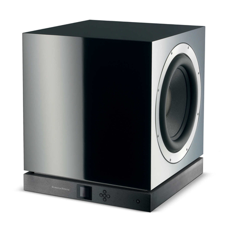
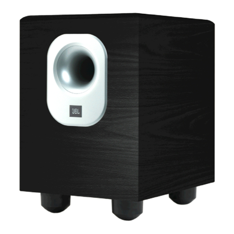
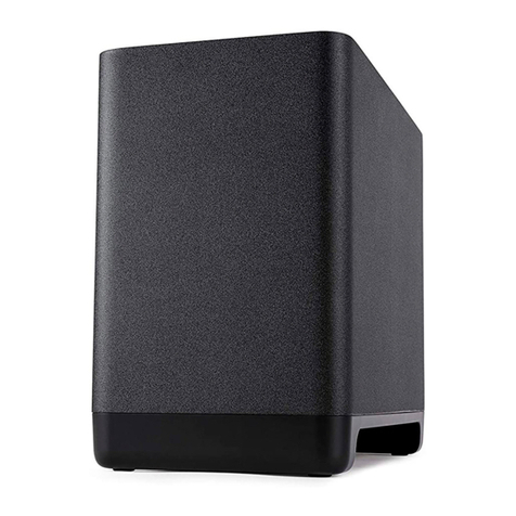
Pronomic SA-15 SUB User manual

Active Subwoofer
Version 04/2019
MIDI
MMC
Pronomic SA-15 SUB/SA-18 SUB
00057895/ 00057897
MIDI
MMC
Manual

PRECAUTIONS
Please read carefully before proceeding
Warning:
Alwaysfollowthebasicprecautionslistedbelowtoavoidthepossibilityofseriousinjuryoreven
deathfrom:electricalshock,short-circuiting,damages,fireorotherhazards.Theseprecautionsin-
clude, but are not limited to,the following:
Power supply / power cord (devices with power cords/power supplies):
•
Onlyusethevoltagespecifiedascorrectforthedevice.Therequiredvoltageisprintedonthe
typeplateofthedevice.Checkthepowercablefromtimetotimeregardingdirt,damageorother
influence.
•
Useonlytheincludedpowercord
/
powersupplyoradaptor.Donotplacethepowerchordnear
heatsourcessuchas:heatersorradiators,anddonotexcessivelybendorotherwisedamagethe
cord,placeheavyobjectsonit,orplaceitinapositionwhereanyonecouldwalkon,tripover,or
roll anything overit.
•
Removetheelectricplugfromtheoutletwhenthedeviceisnottobeusedforextendedperiods
oftime,orduringelectricalstorms.Whenremovingtheelectricplugfromthedeviceoranoutlet,
alwaysholdtheplugitselfandnotthecord. Pullingbythecordcandamageit.
•
Toavoidgeneratingunwantednoise,makesurethereisadequatedistance(50cmormore)be-
tweentheACpoweradaptorandthedevice.DonotcoverorwraptheACpoweradaptorwitha
cloth orblanket.
Location:
•
Whensettingupthe device, makesure that the ACoutlet youareusingis easily accessible.If
some trouble or malfunction occurs, immediately turn off the power switch and disconnect the
plug from theoutlet.
Whenyouarenotusingtheproductforalongtime,makesuretounplugthepowercordfromthe
wall ACoutlet.
•
Inadequateventilationcanresultinoverheating,possiblycausingdamagetothedevice(s),or
even fire.
•
Donot expose the device toexcessive dust orvibrations, orextreme coldorheat (such as: indi-
rectsunlight,nearaheater,orinacarduringtheday)topreventthepossibilityofpaneldisfigura-
tion ordamage to the internal components.
•
Donotplacethedeviceinanunstablepositionwhereitmightaccidentallyfallover.
•
Donotblockthevents.Thisdevicehasventilationholesatthebottom/reartopreventtheinter-
naltemperaturefrombecomingtoohigh.Inparticular,donotplacethedeviceonitssideorup-
side down.
•
Donotusethedeviceinthevicinityof:aTV,radio,stereoequipment,mobilephone,orother
electricdevices.Doingsomayresultinnoise,bothinthedeviceitselfandintheTVorradionext
to it.
Connections and handling:
•
Beforeconnectingthedevicetootherdevices,turnoffthepowerforalldevices.Beforeturning
thepoweron oroff forall devices, set allvolume levelstominimum.

•
Donotusethedeviceorheadphonesforalongperiodoftimeatahighoruncomfortablevol-
umelevel,sincethiscancausepermanenthearingloss.Ifyouexperienceanyhearinglossorring-
ing in the ears, consult a physician.
•
Donotrestyourweightonthedeviceorplaceheavyobjectsonit,andavoiduseexcessiveforce
onthe buttons, switches or connectors
Do not open:
•
Donotopenthedeviceorattempttodisassembletheinternalpartsormodifytheminanyway.
Thedevicecontainsnouser-servicableparts.Ifitshouldappeartobemalfunctioning, discontinue
useimmediatelyandhave itinspectedbyqualifiedservicepersonal.
Water warning:
•
Donotexposethedevicetorain,useitnearwaterorindamporwetconditionsonitcontaining
liquids which might spill into any openings. Never insert or remove an electric plug with wet hands.
If you notice any abnormality:
•
Ifthepowercordorplugbecomesfrayedordamaged,orifthereisasuddenlossofsounddur-
inguseofthedevice,orifanyunusualsmellsorsmokeshouldappeartobecausedbyit,immedi-
atelyturnoffthepowerswitch,disconnecttheelectricplugfromtheoutlet,andhavethedevice
inspected byqualified service personnel.
Installation
GETTING STARTED
Placethespeakeronasolidflatsurfaceoruseasolidspeaker standwith
35mm
flange. Make surethat all fixings are tight.
Ø = 35mm
Power connection and wiring
Pleaseconnectthepowercableto115/220(230)V50/60Hzpowervoltage.Make
suretosetthe
power input selector tothe available net voltage. Connect all
input/output signals with XLR and/or
6.3mmjackcables.
Afteryoufinishedallaudioconnectionssetmastervolume(ifavailable)to“0”.
Switchonaudio
source.SetMic/Linelevelto12o'clockpositionandincrease
mastervolumeto
comfortable level.

Control Panel
1 2 3 4 5 6 7 8 9
10 11
1
Phase switch
Thisswitchreversesthepolarityofthesub-
woofer.
2
Crossover switch
Thisswitchactivatesthehighpassfilterfor
the outputs.
3
POWER LED SIGNAL LED LIMIT LED
4
Line level controll
Rotarylevelcontrol:Attenuatesthelevel
of
thesignalsenttothesubwoofer speaker.
5 Left output
UsethisXLRconnectorforanexternalactive
speaker.
6
Left input
UsethisXLRconnectorforanexternalmixer
or sourcedevice.
7
GND LIFT
This switch lift the ground of the balanced
audio inputs from the earth-ground of the
amplifier.
8
Right input
UsethisXLRconnectorforanexternalmixer
or sourcedevice.
9
Right output
UsethisXLRconnectorforanexternalactive
speaker.
10
AC Power
Use this connector for the power cable.
11
ON/OFF Power Switch
Speaker is "ON" when the switch is in the
"I" position, use this switch to set the
speaker power to ON or OFF.
.
XLR Wiring
Balanced Wiring
1
Ground/Shielding
3
Signal(-)
2
Signal (+)
Unbalanced Wiring
1
Ground/Shielding
3
Bridged to Pin 1
2
Signal (+)

Examples of Use
Fullrange Configuration
High Pass Crossover Configuration

Technical Specifications
MODEL
SA-15 SUB
SA-18 SUB
System Type
Vented Box Subwoofer
Vented Box Subwoofer
LF CONE
15“
18“
LF VOICE COIL
2“ VC
2,5“ VC
LINE INPUT
2 x XLR-F IN
2 x XLR-F IN
LINE OUTPUT
2 x XLR-M OUT
2 x XLR-M OUT
CROSSOVER OUTPUT
FLAT or 100 Hz High-Pass
FLAT or 100 Hz High-Pass
RMS POWER
350 W
350 W
PEAK POWER
700 W
700 W
FREQUENCY RESPONSE
20hz-120khz
20hz-120khz
PEAK SPL
128 dB
128 dB
DIMENSIONS
37x57x30 cm (WxHxD)
44x62x42 cm(WxHxD)
WEIGHT
22.5 Kg
29 Kg

WEEE Declaration
Your product is designed and manufactured with materials and components of high quality, which are recyclable and can be
reused. The symbol means that your product should be disposed of separately from household waste when it reaches its end of
life. Please dispose of this equipment at your local collection point or recycling center. Please help to protect the world in which
we all live.
All specifications and appearances are subject to change without notice. All informations were correct at time of printing.
Musikhaus Kirstein GmbH does not guarantee for the accuracy or completeness of any description, photograph or statement
contained in this manual. Printed colors and specifications may vary slightly from product. Products from Musikhaus Kirstein
GmbH are only sold through authorized dealer. Distributors and dealers are not agents of Musikhaus Kirstein GmbH and have
no authority to bind Musikhaus Kirstein GmbH legally in any way. This manual is protected by copyright. Any copying or reprint,
even in excerpts, is only allowed with written consent of Musikhaus Kirstein GmbH. The same applies to reproduction or
copying of images, even in altered form.
Musikhaus Kirstein GmbH
Bernbeurener Straße 11
D-86956 Schongau
Telefon: 0049-8861-909494-0
Telefax: 0049-8861-909494-19
www.kirstein.de
This manual suits for next models
3
Table of contents
