pSemi PE43665 User manual


PE43665
Evaluation Kit (EVK) User’s Manual
Page ii DOC-90612-1 – (06/2019)
www.psemi.com
Copyright and Trademarks
©2019, pSemi Corporation. All rights reserved. The Peregrine Semiconductor name, Peregrine Semiconductor
logo and UltraCMOS are registered trademarks and the pSemi name, pSemi logo, HaRP and DuNE are trade-
marks of pSemi Corporation in the U.S. and other countries.
Disclaimers
The information in this document is believed to be reliable. However, pSemi assumes no liability for the use of
this information. Use shall be entirely at the user’s own risk. No patent rights or licenses to any circuits
described in this document are implied or granted to any third party. pSemi’s products are not designed or
intended for use in devices or systems intended for surgical implant, or in other applications intended to support
or sustain life, or in any application in which the failure of the pSemi product could create a situation in which
personal injury or death might occur. pSemi assumes no liability for damages, including consequential or
incidental damages, arising out of the use of its products in such applications.
Patent Statement
pSemi products are protected under one or more of the following U.S. patents: patents.psemi.com
Sales Contact
Corporate Headquarters
9369 Carroll Park Drive, San Diego, CA, 92121
858-731-9400

DOC-90612-1 – (06/2019) Page iii
www.psemi.com
PE43665
Evaluation Kit (EVK) User’s Manual
Introduction - - - - - - - - - - - - - - - - - - - - - - - - - - - - - - - - - - - - - - - - - - - - - - 1
Application Support . . . . . . . . . . . . . . . . . . . . . . . . . . . . . . . . . . . . . . . . . . . . . . . . . . . . . . . . . . . . . . . . . . . . . . . . . . . . . . . . . . . . 1
Evaluation Kit Contents and Requirements . . . . . . . . . . . . . . . . . . . . . . . . . . . . . . . . . . . . . . . . . . . . . . . . . . . . . . . . . . . . . . . 1
Kit Contents . . . . . . . . . . . . . . . . . . . . . . . . . . . . . . . . . . . . . . . . . . . . . . . . . . . . . . . . . . . . . . . . . . . . . . . . . . . . . . . . . . . . . . . . . . . . . . . . . . . . . . . 1
PC Requirements . . . . . . . . . . . . . . . . . . . . . . . . . . . . . . . . . . . . . . . . . . . . . . . . . . . . . . . . . . . . . . . . . . . . . . . . . . . . . . . . . . . . . . . . . . . . . . . . . . 1
Instrumentation Requirements . . . . . . . . . . . . . . . . . . . . . . . . . . . . . . . . . . . . . . . . . . . . . . . . . . . . . . . . . . . . . . . . . . . . . . . . . . . . . . . . . . . . . 2
Evaluation Board Assembly - - - - - - - - - - - - - - - - - - - - - - - - - - - - - - - - - - - - 3
Evaluation Board Assembly Overview - - - - - - - - - - - - - - - - - - - - - - - - - - - - - - - - - - - - - - - - - - - - 3
Peregrine USB Interface Board - - - - - - - - - - - - - - - - - - - - - - - - - - - - - - - - - - - - - - - - - - - - - - - - 4
Quick Start Guide - - - - - - - - - - - - - - - - - - - - - - - - - - - - - - - - - - - - - - - - - - - 5
Quick Start Overview - - - - - - - - - - - - - - - - - - - - - - - - - - - - - - - - - - - - - - - - - - - - - - - - - - - - - - - - - - - - - - - 5
Software Installation - - - - - - - - - - - - - - - - - - - - - - - - - - - - - - - - - - - - - - - - - - - - - - - - - - - - - - - - - - - - - - - 5
USB Interface Driver . . . . . . . . . . . . . . . . . . . . . . . . . . . . . . . . . . . . . . . . . . . . . . . . . . . . . . . . . . . . . . . . . . . . . . . . . . . . . . . . . . . 5
EVK Software . . . . . . . . . . . . . . . . . . . . . . . . . . . . . . . . . . . . . . . . . . . . . . . . . . . . . . . . . . . . . . . . . . . . . . . . . . . . . . . . . . . . . . . . . 5
Evaluation Solution Assembly - - - - - - - - - - - - - - - - - - - - - - - - - - - - - - - - - - - - - - - - - - - - - - - - - 8
Connection of the USB Interface Board to the Evaluation Board . . . . . . . . . . . . . . . . . . . . . . . . . . . . . . . . . . . . . . . . . . . . 8
Hardware Configuration - - - - - - - - - - - - - - - - - - - - - - - - - - - - - - - - - - - - - - - - - - - - - - - - - - - - 9
Evaluation Board Schematic . . . . . . . . . . . . . . . . . . . . . . . . . . . . . . . . . . . . . . . . . . . . . . . . . . . . . . . . . . . . . . . . . . . . . . . . . . . . 9
Functional Overview - - - - - - - - - - - - - - - - - - - - - - - - - - - - - - - - - - - - - - - - - - - - - - - - - - - - - - 10
Evaluation Board . . . . . . . . . . . . . . . . . . . . . . . . . . . . . . . . . . . . . . . . . . . . . . . . . . . . . . . . . . . . . . . . . . . . . . . . . . . . . . . . . . . . .10
Hardware Operation . . . . . . . . . . . . . . . . . . . . . . . . . . . . . . . . . . . . . . . . . . . . . . . . . . . . . . . . . . . . . . . . . . . . . . . . . . . . . . . . . . 11
Graphical User Interface - - - - - - - - - - - - - - - - - - - - - - - - - - - - - - - - - - - - - - - - - - - - - - - - - - - 12
Graphical User Interface Controls - - - - - - - - - - - - - - - - - - - - - - - - - - - - - - - - - - - - - - - - - - - - - 13
Part Number Selection . . . . . . . . . . . . . . . . . . . . . . . . . . . . . . . . . . . . . . . . . . . . . . . . . . . . . . . . . . . . . . . . . . . . . . . . . . . . . . . . 13
Device Information . . . . . . . . . . . . . . . . . . . . . . . . . . . . . . . . . . . . . . . . . . . . . . . . . . . . . . . . . . . . . . . . . . . . . . . . . . . . . . . . . . . 13
Latched Parallel and Serial Mode . . . . . . . . . . . . . . . . . . . . . . . . . . . . . . . . . . . . . . . . . . . . . . . . . . . . . . . . . . . . . . . . . . . . . . .13
Table of Contents

PE43665
Evaluation Kit (EVK) User’s Manual
Page iv DOC-90612-1 – (06/2019)
www.psemi.com
Continuous Pattern Loop . . . . . . . . . . . . . . . . . . . . . . . . . . . . . . . . . . . . . . . . . . . . . . . . . . . . . . . . . . . . . . . . . . . . . . . . . . . . . .14
Attenuation Value . . . . . . . . . . . . . . . . . . . . . . . . . . . . . . . . . . . . . . . . . . . . . . . . . . . . . . . . . . . . . . . . . . . . . . . . . . . . . . . . . . . .14
Attenuation Slide Bar . . . . . . . . . . . . . . . . . . . . . . . . . . . . . . . . . . . . . . . . . . . . . . . . . . . . . . . . . . . . . . . . . . . . . . . . . . . . . . . . .14
Technical Resources - - - - - - - - - - - - - - - - - - - - - - - - - - - - - - - - - - - - - - - - 17
Technical Resources - - - - - - - - - - - - - - - - - - - - - - - - - - - - - - - - - - - - - - - - - - - - - - - - - - - - - - 17

DOC-90612-1 – (06/2019) Page 1
www.psemi.com
1
PE43665
Evaluation Kit (EVK) User’s Manual
The PE43665 is a 75Ω, high linearity, 6-bit RF digital step attenuator (DSA) that supports a frequency range
from 1 MHz to 2 GHz. The PE43665 provides an integrated digital control interface that supports both serial and
parallel (direct and latched) programming of the attenuation.
The PE43665 covers an 31.5 dB attenuation range in 0.5 dB steps. In addition, no external blocking capacitors
are required if 0 VDC is present on the RF ports.
The PE43665 evaluation kit (EVK) includes the application software and hardware required to control and
evaluate the functionality of the DSA using a PC running the Windows®operating system to control the USB
interface board.
Application Support
For any technical inquiries regarding the evaluation kit or software, please visit applications support at
www.psemi.com (fastest response) or call (858) 731-9400.
Evaluation Kit Contents and Requirements
Kit Contents
The PE43665 DSA EVK includes the following hardware required to evaluate the device:
PC Requirements
The PE43665 DSA Evaluation Software requires a computer with the following minimum requirements:
• PC with Windows XP, Vista, 7, 8 or 10
• Mouse or other pointing device
• USB port
• Web browser with Internet access (for downloading software)
• User account with administrator privileges (for installing software)
Table 1 • PE43665 Evaluation Kit Contents
Quantity Part
Number Description
1 PRT-72713 PE43665 DSA Evaluation Board Assembly
1 PRT-69137 Kit, USB Interface Board (Blue), 8 bit, 2.5V IO, with 3-foot cable
Introduction

PE43665
Evaluation Kit (EVK) User’s Manual
Page 2 DOC-90612-1 – (06/2019)
www.psemi.com
Instrumentation Requirements
In order to evaluate the step attenuator performance of the evaluation board, the following equipment is
required:
• Power supply
• 3.0 VDC with 0.5A minimum
• DC cables (banana to Mini-Grabber suggested)
• Vector network analyzer
• F-type RF cables or adapters
• Minimum loss pads for 50 Ohm impedance conversion
Caution: The PE43665 DSA EVK contains components that may be damaged by exposure to voltages in
excess of the specified voltage, including voltages produced by electrostatic discharges. Use care when
handling the board. Always handle in accordance with procedures for handling static-sensitive components.
Avoid applying excess voltages to or touching the power supply terminals, RF ports or digital inputs.


PE43665
Evaluation Kit (EVK) User’s Manual
Page 4 DOC-90612-1 – (06/2019)
www.psemi.com
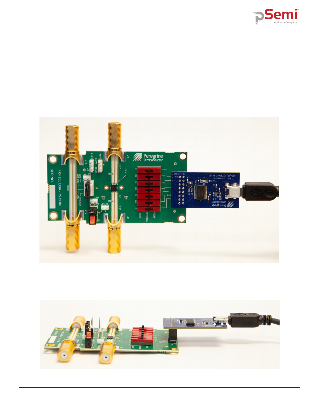
Peregrine USB Interface Board
The USB interface board (Figure 2) is included in the evaluation kit. This board allows the user to control the
digital input signals at the PE43665 device by using pSemi software running the Windows operating system. To
install the driver software, see “Software Installation” on page 5.
Figure 2 • Peregrine USB Interface Board
DOC-90612-1 – (06/2019) Page 5
www.psemi.com
PE43665
Evaluation Kit (EVK) User’s Manual
3
Quick Start Guide
Quick Start Overview
The EVB assembly was designed to ease customer
evaluation of the PE43665 digital step attenuator. This
section will guide the user through the software instal-
lation, the hardware configuration, and the features of
the graphical user interface (GUI).
Software Installation
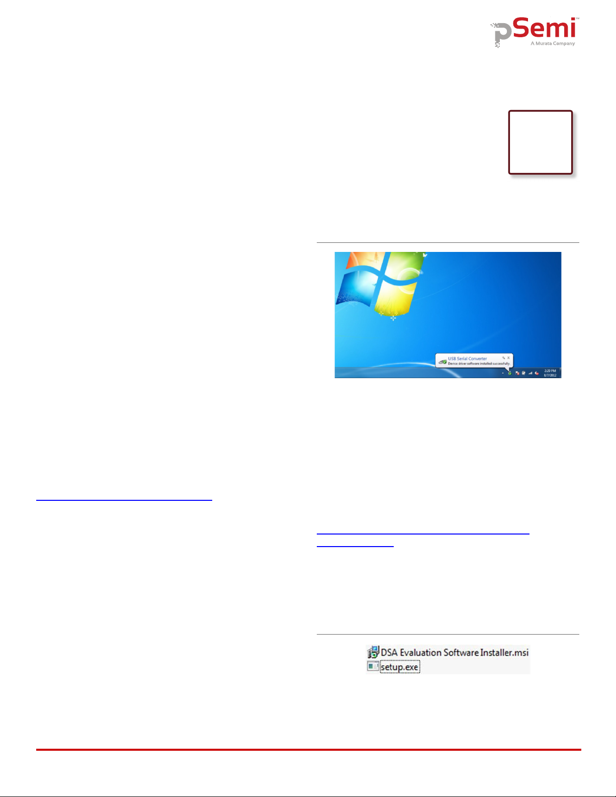
USB Interface Driver
The latest USB interface board drivers are available via
Microsoft Windows®Update. Internet connectivity is
required to download the drivers. Connect the USB
interface board to the PC and select the Windows
Update option to obtain and install the drivers
(Figure 3).
In the case where Windows Update is not available; the
USB interface board driver may be downloaded directly
from the manufacturer at the following URL:
www.ftdichip.com/Drivers/D2XX.htm
Select the link for the appropriate Windows operating
system driver. It is recommended to select the “Setup
Executable” option when choosing the driver to
download.
A USB interface board (Figure 2) is included with the
evaluation kit, and driver installation completed prior to
attempting communicating with the PE43665 DSA
evaluation board.
EVK Software
To evaluate the PE43665 EVK performance, the appli-
cation software must be installed on your computer.
The USB interface and PE43665 DSA Evaluation
software is compatible with computers running
Windows XP, Windows Vista, Windows 7, Windows 8,
or Windows 10 in 32- or 64-bit configurations. This
software is available for download as a .zip file
directly from the pSemi website at the following URL:
http://www.psemi.com/products/digital-step-
attenuators-dsa
To install the PE43665 DSA Evaluation Software, unzip
the archive to a named folder of your choice and
execute the installer application “setup.exe”
(Figure 4).
After the setup.exe file has been executed, a welcome
screen appears. It is strongly recommended that all
programs be closed prior to continuing. Click the “Next”
button to proceed (Figure 5).
Figure 3 • USB Driver Installation (Detecting)
Figure 4 • DSA Evaluation Software Setup.exe File

PE43665
Evaluation Kit (EVK) User’s Manual
Page 6 DOC-90612-1 – (06/2019)
www.psemi.com
Review the license agreement, select “I agree,” and then
click “Next.” (Figure 6).
Select the desired location for the installation directory. It
is recommended to accept the default location.
The next window allows the user to confirm the instal-
lation choices before beginning the installation process.
Click “Next” to proceed with the software installation
(Figure 8). Please note that the installation of software
requires Administrator privileges under the Windows
operating system.
As the software files are installed, an indicator displays
the progress. On slower computers, installation of the
Figure 5 • DSA Evaluation Software Setup
Figure 6 • License Agreement
Figure 7 • Default Installation Location
Figure 8 • Confirm Installation

DOC-90612-1 – (06/2019) Page 7
www.psemi.com
PE43665
Evaluation Kit (EVK) User’s Manual
software may take a few minutes
(Figure 9).
You may be prompted to confirm the installation of the
application. Confirm that the “Verified publisher” is
“pSemi Corporation” before proceeding (Figure 10).
Upon successful installation, a confirmation message is
displayed. Click “Close” to exit (Figure 11).
A new folder named “pSemi Corporation” appears in the
start menu of your computer. Select “DSA Evaluation
Software” to launch the evaluation software (Figure 12).
Figure 9 • Installation Progress Display
Figure 10 • User Access Control Confirmation Dialog
Figure 11 • Installation Complete
Figure 12 • DSA Evaluation Software Start Menu Item
PE43665
Evaluation Kit (EVK) User’s Manual
Page 8 DOC-90612-1 – (06/2019)
www.psemi.com
Evaluation Solution Assembly
Connection of the USB Interface Board to the Evaluation Board
The evaluation board and the USB interface board contain a 16-pin header. This feature allows the USB
interface board (socket) to connect directly to the evaluation board (pin) on the front-side as shown in Figure 13.
Use caution when connecting the USB Interface board to ensure that the two rows of pins are connected without
shifting in any direction.
Figure 13 • PE43665 USB Interface Board Connected to the Evaluation Board for Latched Parallel and Serial
Programming—Front View
Figure 14 • PE43665 USB Interface Board Connected to the Evaluation Board for Latched Parallel and Serial
Programming—Side View
DOC-90612-1 – (06/2019) Page 9
www.psemi.com
PE43665
Evaluation Kit (EVK) User’s Manual
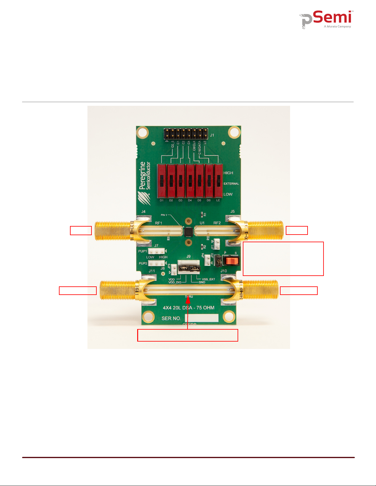
Hardware Configuration
The evaluation board is designed to ease customer evaluation of pSemi’s products. The board contains:
1) Digital signal connectors that are connected for power supply, digital control signals and USB interface board.
2) F-type connectors that are provided for RF performance verification and THRU trace to calibrate board trace
loss.
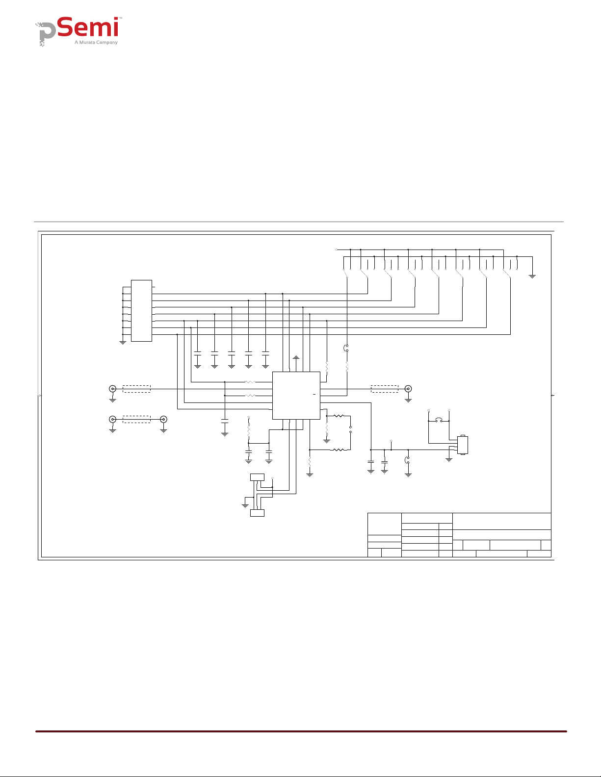
Evaluation Board Schematic
The schematic of the evaluation board is provided in the following section:
Figure 15 • PE43665 DSA Evaluation Board Schematic
1. CAUTION:
CONTAINS PARTS AND ASSEMBLIES SUSCEPTIBLE
NOTES:
TO DAMAGE BY ELECTROSTATIC DISCHARGE (ESD)
A
B
C
D
54321
D
C
B
A
2345
R. PROAL
08-03-18
SCHEMATIC, PE43665 EVK
01DOC-90222
San Diego, CA 92121
9380 Carroll Park Drive
SIZE DWG NO.
SHEET 1 OF 1
DATE
REV
SCALE:ISSUED
APPROVED
CHECKED
ENGINEER
DRAWN DATE
DATE
DATE
DATE
DATE
UNLESS OTHERWISE SPECI FIED
DIMENSIONS AND TOLERANCES
ARE IN INCHES AND
APPLY TO THE FINISHED PART
TOLERANCES ARE:
FRACTIONS DECIM ALS
± .XX ± .01
.XXX ± .005
DO NOT SCALE DRAWING
CONTRACT NO.
MATERIAL
SIMILAR TO MARKING SYMBOL
FINISH B
NONE
1
pSemi Corporation
J. FLYNN
08-03-18
Z=75 Ohm
THRU
SUPPLY
-
DNI
2. INSTALL SHUNT CONNECTOR ON JP2, JP3 AND JP4.
Z=75 Ohm
Z=75 Ohm
3
1
2
4
D3
C1
100pF
5
4
6
P/S
C6
100pF
3
1
2
4
D4
C4
100pF
3
1
2
4
D5
C3
100pF
3
1
2
4
D6
3
1
2
4
D1
C2
100pF
3
1
2
4
D2
C5
100pF
C16
0.1uF
C13
100pF
C18
0.1uF
R3
10K
C17
100pF
R8
10K
1
2
3
4
J9
R5
0 OHM
21
43
65
87
10 9
12 11
14 13
16 15
J1
HEADER16
1
2
3
J8
1
2
3
J7
R1
0 OHM
R2
0 OHM
R4
0 OHM
R6
0 OHM
R7
DNI
R9
DNI
3
1
2
4
LE
J4 J5
J10 J11
12
JP1
12
JP2
12
JP3
12
JP4
1C16
2RF1
3DATA
4CLK
5LE
6VDD
7PUP1
8PUP2
9VDD
10 GND
11
GND
12
VSS_EXT
13
P/S
14
RF2
15
C8
16
C4
17
C2
18
GND
19
C1
20
C0.5
U1
PE43665
VDD_DIG
VSS_EXT
PUP2
PUP1
C0_5
C1
C2
C4
C8/CLK
C16/DATA
LE
VDD_DIG
VDD
VDD
VDD_DIG
PE43665
Evaluation Kit (EVK) User’s Manual
Page 10 DOC-90612-1 – (06/2019)
www.psemi.com
Functional Overview
Evaluation Board
Figure 16 illustrates the connections on the RF evaluation board used in evaluating the PE43665 DSA.
Figure 16 • PE43665 DSA Evaluation Board Functional Overview
THRU RF in/out THRU RF in/out
RF in/out RF in/out
Apply external power
J9–4 connection point for VDD
J9–3 connection point for VDD_DIG
J9–2 GND
J9–1 connection point for EXT_VSS
“THRU” trace is for board trace loss calibration

DOC-90612-1 – (06/2019) Page 11
www.psemi.com
PE43665
Evaluation Kit (EVK) User’s Manual
Hardware Operation
The following steps prepare the evaluation solution for power up and making measurements. Please follow the
guidelines and verify the connections with the supplied schematic before applying power.
1) Verify all DC power supplies are turned off before proceeding.
2) Calibrate board trace loss with THRU trace test coupon between J4 and J5. THRU calibration is sufficient for
initial measurements. Use one-half the loss of the measured trace for each port, as this will de-embed one
connector and half the trace. If more accurate results are desired, a full vector de-embedding can be done
with the THRU trace that matches your de-embedding technique.
3) Provide external power supply for VDD on J9. Pin 4, VDD CTL on J9 pin 3, GND on J6 pin 2, and EXT_VSS on
J9 pin 1. (Table 2).
4) Ensure switch P/S (parallel/serial) switch position matches the desired control type used via the PC software
(parallel/serial) or manual control (parallel)
5) Move switches D1–D6 and LE to the center position "EXT" when using the PC software and USB interface
board to control the DSA.
6) When controlling the DSA without the PC software and USB interface board, use switches D1–D6 and LE to
positions HIGH and LOW to set the desired digital input.
Table 2 • Recommended Operating Condition for the PE43665
Parameter Min Typ Max Unit
Positive supply voltage, VDD 2.7 3.0 3.3 V
Positive supply current, IDD 8100µA
Digital input high(1) 0.7 x VDD V
Digital input low 0 0.3 x VDD V
Digital input current 1 µa
Notes:
1) This voltage is named VDD_DIG on EVK J9 pin 3 and is used to manually set a logic “1” when using manual slide switches to force the logic
levels. The Peregrine dongle is a 2.5V logic device.

PE43665
Evaluation Kit (EVK) User’s Manual
Page 12 DOC-90612-1 – (06/2019)
www.psemi.com
Graphical User Interface
Figure 17 displays the DSA application software graphical user interface (GUI), which has the USB interface
board plugged into the computer. See “Hardware Operation” on page 11 for the EVK hardware configuration to
enable use with the GUI control software.
If the USB interface board is not connected when the application software is launched, the message “No
interface board connected. Please connect USB-SPI Interface #101-0695” appears at the bottom of the screen.
The message “USB-SPI Interface Board 101-0695 connected” is displayed when the USB adapter is connected
and recognized.
In the upper left corner, under the pSemi logo, use the drop down menu to select the part for evaluation. The
part description appears in the box below the part number.
Figure 17 • PE43665 DSA Evaluation Software Graphical User Interface

DOC-90612-1 – (06/2019) Page 13
www.psemi.com
PE43665
Evaluation Kit (EVK) User’s Manual
Graphical User Interface Controls
Part Number Selection
The drop down control (Figure 18) allows the user to select the type of attenuator to control. To evaluate the
PE43665, ensure PE43665 is selected. The device information section is updated when the selected device is
changed.
Device Information
The device information area displays some basic information about the device that has been selected. Infor-
mation consists of interface type, maximum attenuation, number of digital bits, and attenuation step size.
Latched Parallel and Serial Mode
The DSA application software supports both serial and latched parallel device modes. Select the desired mode
by choosing either “Latched Parallel” or “Serial” on the left side of the application. This radio button will set the
P/S input level to the device when the radio button is clicked.
The Send button changes functionality based on the control interface mode. Send Latch in Latched Parallel
mode and Send Signal in Serial mode are provided to resend the programming bits to the device at the same
attenuation state.
Figure 18 • Graphical User Interface Part Number Selection
Figure 19 • Graphical User Interface Device Information

PE43665
Evaluation Kit (EVK) User’s Manual
Page 14 DOC-90612-1 – (06/2019)
www.psemi.com
Continuous Pattern Loop
Click the Continuous Pattern Loop check box to step through each of the attenuation states. The pause interval
can be specified in seconds to adjust the time in between sending each pattern.
Attenuation Value
The Attenuation Value box displays the attenuation value the DSA is currently programmed to. Type the desired
attenuation value and then click “Enter” key to program the DSA.
Attenuation Slide Bar
The attenuation slide bar in the center of the GUI allows the user to quickly select the desired attenuation. Use
the mouse to drag the red rectangle to the desired setting. The red arrows at the top and bottom can be clicked
to increase or decrease attenuation state at the minimum step size.
Figure 20 • Latched Parallel and Serial Mode GUI Features
Figure 21 • Continuous Pattern Loop Settings
Figure 22 • Attenuation Value


Table of contents
Popular Motherboard manuals by other brands


Albatron
Albatron P4M800 Pro user manual

Texas Instruments
Texas Instruments bqSWITCHER bq241 EVM Series user guide

Torex
Torex XCL206B303-EVB user manual

Supermicro
Supermicro X5DPA-8GG user manual

Analog Devices
Analog Devices EV1HMC6832ALP5L user guide

Intel
Intel DP55WB - Media Series P55 micro-ATX Core i7 i5 LGA1156 Desktop... specification


