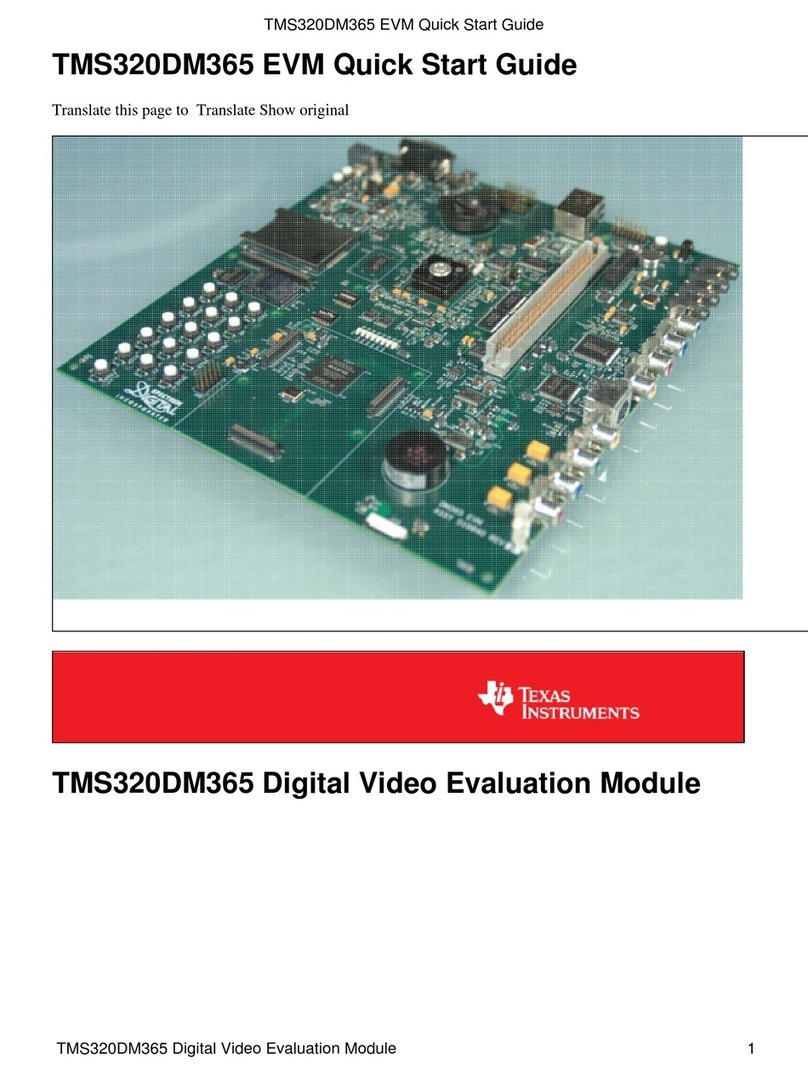
6Choose the OS demo of
interest and insert the
appropriate SD card into the
AM335x EVM as shown.
5Remove the protective plastic
from the LCD touchscreen.
4Connect the Ethernet cable to
the RJ-45 jack located on the
AM335x baseboard. Connect
the other end of the cable to an
Internet-enabled router or
Ethernet switch.
1Verify SW3/SW4 DIP switches
are set as shown. SW3/SW4 are
located on the back of the
AM335x EVM.
Welcome to the AM335x Evaluation Module (EVM) Quick Start Guide. This guide is designed to help you through the
initial setup of your EVM. This EVM allows you to experience both Linux™ and Android™ operating systems that
®
showcase the AM335x Cortex™-A8 processor, 3D graphics, Wi-Fi™/Bluetooth based on WL1271, and much more. The
AM335x EVM contains the following:
• Hardware
– AM335x general-purpose baseboard with:
TPS65910 power management IC
WL1271 Wi-Fi/Bluetooth module
– AM335x general-purpose daughtercard with:
additional I/O
audio
navigation
– 7" WVGA LCD touchscreen daughtercard
– USB and serial cables
– Stylus
– Universal power supply with regional adapter
– USB SD card reader
•
•
•
•
•
•
AM3358 processor
• Printed documents
– AM335x EVM Quick Start Guide (this document)
– Android and Linux SDK SD card contents sheet
– Software license agreement
• Software and soft copy documents
– AM335x Linux Software Development Kit (SDK)
– AM335x Android Development Kit
Default setup (OS boot from SD card)
3Connect the supplied serial
cable to the UART DB-9 (J12)
connector located on the
AM335x baseboard. NOTE:
There are five additional UARTs
for development but cannot be
used for demo purposes.
2Ensure SW6 DIP switch is set
as shown (OFF). SW6 is located
on the AM335x daughtercard.
7Connect the power cable to the
power jack on the baseboard. 8Set SW1 on the AM335x EVM
baseboard as shown.
NOTE: Power is on when switch
is nearest the power cable.
AM335x EVM Board Back
4
8
AM335x EVM Board Front
3
1
5
6
7
4GB
AM335x EVM
®
ARM
Microprocessors
2*
*2 SW6 switch is located beneath the flap
Continued on following page
