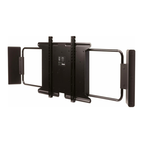
Q Acoustics Q-TV2 User manual

User Manual
for 30”- 42”Screens
Q-TV2

09 Your Connections
10 Connecting via Mini Jack
11 Connecting via PHONO (RCA)
12 Connecting Optical (Toshlink)
13 AUX Inputs (e.g iPod®)
Overview
Ü
02 Safety Guidelines
03 Getting started
03 Potential Uses
04 Carton Contents
05 Q-TV2 Controls
05 Remote
Introduction
15 Connecting via Mini Jack
16 Connecting via SCART
Q Acoustics offers a One Year Warranty on parts and
labour from date of purchase.
Products must be purchased from an authorised
Q Acoustics Dealer and must be returned to that
Dealer with proof of purchase for service or repair.
Please contact your authorised Dealer for its policy on
returns and replacements.
14 Setup
14 Lip-Sync
06 Fixing Rails
07 Fitting Q-TV2
08 Adjusting Q-TV2 arms
Q Acoustics Q-TV2 is the latest
innovative audio solution in the
Q-AV range.
Using the latest slim line speaker
technology within an easy to
setup solution, this product is
designed to disappear within the
room without compromising
performance.
Alternative Connections
17 Troubleshooting
18 Specification
Troubleshooting
Warranty
Setup
Fixings
Connections
Thank you for purchasing Q Acoustics Q-TV2.
This Manual is intended to take you through the setup
and installation of Q-TV2. From choosing the correct
connection for your system to mounting the unit
itself, this is a guide to a trouble free setup.
We hope that you enjoy the Q-TV2 experience.
Q Acoustics Design Team
Contents
Ü
Quick Start Guide
Page 1

CAUTION!
RISK OF ELECTRIC SHOCK
DO NOT OPEN
TO REDUCE THE RISK OF ELECTRIC SHOCK DO NOT REMOVE COVER (OR BACK)
NO USER-REMOVEABLE PARTS INSIDE
REFER SERVICING TO QUALIFIED PERSONNEL
This symbol indicates that there are important operating and
maintenanceinstructionsintheliteratureaccompanyingthisunit.
This symbol indicates that dangerous voltage constituting a risk of
electricshockispresentwithinthisunit.
5A FUSE
BS 1362
BROWN
(Live)
BLUE
(Neutral)
Important Information- Please Read Carefully
3A FUSE
BS 1362
BROWN
(Live)
BLUE
(Neutral)
Safety
Ü
Quick Start Guide
Page 2
When a cart is used, use caution when
Read these instructions.
moving the cart/ apparatus
Keep these instructions.
combination to avoid injury from tip-
Heed all warnings. over.
Followall instructions. Unplug this apparatus during lightning
storms or when unused for long periods
Do not use this apparatus near water. of time. Importantnotice to UK users
Clean only with dry cloth. The appliance cord is terminated with a
Refer all servicing to qualified service UK approved mains plug fitted with a 3A
Do not block any ventilationopenings. personnel. Servicing is required when fuse. If
Install in accordance with the the apparatus has been damaged in any
manufacturer's instructions. way, such as power supply cord or plug is
damaged, liquid has been spilled or
Do not install near any heat sources such objects have fallen into the apparatus,
as radiators, heat registers, stoves, fire the apparatus has been exposed to rain
places etc. or moisture, does not operate normally,
or has been dropped.
Do not defeat the safety purpose of the
Warning: To reduce the risk of fire or
polarized or grounding type plug. A
electrical shock, do not expose this
polarized plug has two blades with one
product to rain or moisture. The product
wider than the other. A grounding type
must not be exposed to dripping and
plug has two blades and a third
splashing and no object filled with
grounding prong. The wider blade or the
liquids such as a vase of flowers should
third prong are provided for your safety.
be placed on the product.
If the provided plug does not fit into your
outlet, consult an electrician for
replacement of the obsolete outlet. No naked flame sources such as candles
should be placed on the product.
Protect the power cord from being
walked on or pinched, particularly at Warning: The mains power switch for
plugs, convenience receptacles, and the the power supply unit is the device used
point where they exit from the to disconnect the unit from the mains
apparatus. supply. This switch is located on the
power supply unit. To permit free access
to this switch, the apparatus must be
Use only attachments/accessories
located in an open area without any
specified by the manufacturer. Use only
obstructions, and the switch must be
with a cart, stand, tripod, bracket, or freely operable.
table specified by the manufacturer, or
sold with the apparatus. Caution: Changes or modifications not
expressly approved by the manufacturer
could void the user's authority to
operate this device.
Third parties: In the unlikely event that
you pass this product on to a third party,
include these operating instructions
with the product.
the fuse needs to be replaced, an
ASTA or BSI approved BS1362 fuse rated
at 3A must be used. If you need to
change the mains plug, remove the fuse
and dispose of this plug safely
immediately after cutting it from the
cord.
Connecting a mains plug
The wires in the mains lead are coloured
in accordance with the code: Blue:
NEUTRAL; Brown: LIVE:
As these colours may not correspond to
the coloured markings identifying the
terminals in your plug, proceed as
follows:
The BLUE wire must be connected to the
terminal marked with the letter N or
coloured BLUE or BLACK. The BROWN
wire must be connected to the terminal
marked with the letter L or coloured
BROWN or RED.
Equipment
Ü
Q Acoustics Q-TV2 is designed to work with minimal disruption to your existing TV setup. Whatever
you already have plugged into your TV will remain in the same place. By using the TV’s audio outputs
you will be able to listen to all of your equipment without the need to run additional wires. Q-TV2 is
designed to connect via only one connection. It is also possible to add an external music source to
the system through the AUX Input.
Q Acoustics Q-TV2 upgrades the sound of your existing TV setup by integrating a 2.1 system on to the
rear of your flat screen TV. Using the TV’s audio outputs Q-TV2 gives a no fuss solution to HD Sound.
Q-TV 2 requires only one audio connection between the TV and itself to significantly improve the
acoustic performance of your flat screen TV. Q-TV2 also acts as a music system when connected to an
external source such as an iPod®or laptop computer.
Important Note
Important Notes are highlighted throughout this manual to show the most important information required to install
this product correctly.
Q Acoustics recommends that you take particular notice of these highlighted pieces of information in order to simplify
the setup process.
Where to Start
Ü
Quick Start Guide
Page 3
External Music Source
e.g iPod®, Laptop Computer
External AV equipment
e.g Sky, DVD Player, Digital
TV
connected to AV equipment
Q-TV2 INPUTS
Connected to
AUX source OUT
Connected to
TV Audio OUT
TV IN
LINE IN
OPTICAL IN
AUX IN

Carton Contents
Ü
Quick Start Guide
Page 4
1 x 16VDC Power Supply 1 x UK Mains Power Cable
2 x Fixing Rails
1x Q-TV2
1 x EU Mains Power Cable
1 x Mini Jack Cable
1 x Fixing Kit
Fixing Kit Contents
1 x RCA / PHONO Cable
4 x Rail Spacer Short
4 x Rail Spacer Long
2 x Security Pin
1 x Remote Control
2x AAA Batteries
1 x Small Allen Key
4 x M4 x 20mm
4 x M4 x 50mm
4 x M4 Shoulder Washer
4 x M5 x 20mm
4 x M5 x 50mm
4 x M5 Shoulder Washer
1 x Large Allen Key
4 x M6 x 20mm
4 x M6 x 50mm
4 x M6 Shoulder Washer
4 x M8 x 25mm
4 x M8 x 50mm

Remote
Ü
01 Optical In 04 AUX IN (Audio Input)
05 TV IN
06 LINE IN
07 SOURCE VOLUME
02 16V DC (Power Input)
03 LED Indicator
Input designed for TV’s with an
optical output.
Audio Input for additional
source such as iPod®or laptop
computer.
Audio Input for connection to
TV headphone socket
Alternative input designed to
connect to TV’s phono sockets.
Disables volume control
(See Setup / Page 14)
Power Input socket for
connection to supplied mains
adapter
Red - No Signal (Standby)
Green - Signal Detected
Orange - Set Delay Active
01 02 0403 05 06 07
08 SET DELAY
09 SET POSITION
Manual audio synchronisation
(See Setup / Page 14)
Change audio setup to suit the
position of your TV
(See Setup / Page 14)
08 09
Important Note
In some cases Q-TV2’s volume can be controlled by your existing
TV remote. This option is only available on certain TV’s when
connected via the TV’s HEADPHONE OUT and Q-TV2’s TV IN.
Please see connections for more details ( Page 9)
TV IN - Use existing TV remote (See page 10)
LINE IN - Remote Needed
OPTICAL IN - Remote Needed
AUX IN - Remote Needed
SET DELAY - Remote Needed
16V 5A
Q-TV2 Controls
Ü
Quick Start Guide
Page 5
VOLUME DOWN
VOLUME UP
MUTE

Fixing
Fitting the Rails
Ü
Longer screws are provided for use with
the spacer kit. If your Screens fixing points
are directly above the connections panel
use the spacers provided (B). The screws
are long enough to allow for a combination
of spacers if needed e.g (B) + (C).
Fix the rails as central to the screen as possible. Check that both rails are equally spaced from the
top and bottom of the screen before fixing. It is very important that the top of the rails are level.
Ensure the clip is at the top of the rail. Select the appropriate Allen key (D) and fasten securely.
Q-TV2 mounts directly to the rear of your TV using
the screens fixing points. Located on the rear of your
screen will be threaded fixing points designed for
wall mounting. Use these fixings to attach Q-TV2.
Every screen is different so Q-TV2 comes with a
fixing kit designed to suit a wide range. Identify the
fixing points on the rear of your screen. Select the
appropriate screws from the fixing kit.
If your fixing points lay close to the connections
panel you may need the spacer kit(see below).
B
B
= 30mm
= 8mm
= 22mm
CBC
C
+
Clip at Top
Screen
Fixing
Fix rails
as central
as possible
Shoulder Washers
Ü
Spacers
Ü
A
A
D
To locate securely in the mounting bracket
three of the four smaller fixings require a
spacer washer(A). Fit these spacers to the
bolts before attaching the rails to the TV.
Fixing Points
Ü
Quick Start Guide
Page 6

Angle Q-TV2 back slightly and
position on the lower rail fixing.
Ensure the connections panel is
at the top.
Push the subwoofer toward the
top fixing.
Important Note Before fastening the subwoofer in place you may
want to fit your connections to the rear of the TV.
Fitting
Ü
Quick Start Guide
Page 7
Secure the top fixing clips.
Ensure both sides are firmly
clipped in place. Insert security
pin (E).
E

If needed the satellite speakers can also be
adjusted vertically by loosening the fastening
screws on the adjustable arms. Slacken off the
screws and move in the desired direction.
Adjustments
Ü
Loosen
Tighten
The satellite speakers are attached to adjustable arms. These arms
are designed to be extended to match the width of your screen.
Loosen all 4 fixing points and extend the arms to match your
screen. Once happy with the positioning tighten the fixings.
Loosen
Tighten
Adjust
Adjustments
Ü
Quick Start Guide
Page 8

No
No
Yes
No No
Yes Yes
HEADPHONE
OUTPUT
Go to Page 12
Go to Page 10 Go to Page 16
Does the TV mute
when the mini jack
lead is inserted?
Does your TV
have other audio
outputs?
Yes
Go to Page 15
No
Yes
Go to Page 11
ANALOGUE
OUTPUT
AUDIO OUT
L
R
OPTICAL
OUT
AUDIO
OUT
DIGITAL
OUTPUT
HEADPHONE
SOCKET
The plug and play solution.
Simple connection to the TV
headphone socket gives full
audio control with the use
of your existing remote
control.
Better quality audio
connection. Volume will be
controlled by the Q-TV2
remote.
OPTICAL
SOCKET
Better quality audio
connection. Volume will be
handled by Q-TV2 remote.
(Optical (Toshlink) cable not
provided)
Headphone connections are often on the side of your TV
(A). If you are unable to find the headphone socket consult
the manufactures handbook.
Phono and Optical Outputs are normally found at the rear
of your TV (B). Ensure that you identify the sockets labelled
AUDIO OUT.
Which Connection?
Where ?
Ü
Ü
Does your TV have one of the following?
Select one of the connections below
A
B
Your Connections
Ü
Quick Start Guide
Page 9
RCA / PHONO
SOCKET

Mini Jack
Select only one of the connections detailed
Mini Jack
HEADPHONES
Connecting the headphone socket will enable you to control the volume of Q-TV2 with your existing
remote control. Locate the Mini Jack lead provided (See page 4), Position both switches on the top of
Q-TV2 to normal and select the most appropriate room position setting, (see page 14). Insert the mini
jack cable from the TV’s HEADPHONE OUT to the TV IN socket on the top of Q-TV2.
NOTE:
If your TV does not mute when the headphone socket is plugged in we recommend either selecting
another connection method (See page 9) or moving the mini jack connection on Q-TV2 (See page 15)
Connections
Ü
Quick Start Guide
Page 10
16V 5A
Connect the power supply provided to Q-TV2. The LED will illuminate when connected.
Use your existing remote control to operate the volume of Q-TV2
Power
Q-TV2
16V 5A
Insert into Q-TV2
Power Cable
UK
EU
Power Supply
Select off
position
before
connection
Power Supply
Select on
position
after
connection
Important Note Do not insert the plug into an electrical outlet
until all other connections have been made
Ü

AUDIO OUT
L
R
Analogue
RCA / PHONO Lead
RCA /PHONO Lead
Locate the remote control and RCA / PHONO lead provided (page 4). Position both switches on the
top of Q-TV2 to normal and select the most appropriate room position setting (see page 14).
Connect the phono lead provided to the TV’s RCA /PHONO connection labelled AUDIO OUT.
Connect the other end to Q-TV2 connection labelled LINE IN. Wire Red to Red and White to White.
Connect the power supply provided to Q-TV2. The LED will illuminate when connected.
Silence your TV speakers by turning the TV volume down to zero, do not mute the TV. Use the Q-TV2
Remote to turn up the volume on Q-TV2. If you experience bad synchronisation between sound and
vision using this connection method view the section on SET DELAY (Lip Sync) (Page 14)
Select only one of the connections detailed
Important Note
Connecting to Q-TV2 via this
method requires that you use the Q-
TV2 remote to operate the volume.
Important Note
Always ensure that TV IN socket is
left vacant when connecting via
LINE IN. Do not insert an additional
source into TV IN.
No Sound ?
Ensure that you have connected to
the TV connections labelled AUDIO
OUT. Always use connections on
the rear of your TV.
Connections
Ü
Quick Start Guide
Page 11
16V 5A
Power
Q-TV2
16V 5A
Insert into Q-TV2
Power Cable
UK
EU
Power Supply
Select off
position
before
connection
Power Supply
Select on
position
after
connection
Important Note Do not insert the plug into an electrical outlet
until all other connections have been made
Ü

Digital
Optical Lead (Not Provided)
Optical Lead
Q-TV2 does not include an optical lead so you will need to purchase one if you wish to connect via
this method. Locate the Q-TV2 remote control. Position both switches on the top of Q-TV2 to normal
and select the most appropriate room position setting. Connect the optical lead from Q-TV2’s
OPTICAL IN to the TV’s optical connection labelled OPTICAL OUT or DIGITAL OUT.
Select only one of the connections detailed
OPTICAL
OUT
AUDIO
OUT
Background Noise ?
Check That your TV’s Optical output
is set to PCM Mode. This unit does
not decode Dolby Digital®or DTS®
bitstream outputs.
Connections
Ü
Quick Start Guide
Page 12
16V 5A
Connect the power supply provided to Q-TV2. The LED will illuminate when connected.
Silence your TV speakers by turning the TV volume down to zero, do not mute the TV. Use the Q-TV2
Remote to turn up the volume on Q-TV2. If you experience bad synchronisation between sound and
vision using this connection method view the section on SET DELAY (Lip Sync) (Page 14)
Important Note
Connecting to Q-TV2 via this
method requires that you use the Q-
TV2 remote to operate the volume.
Important Note
Always ensure that TV IN socket is
left vacant when connecting via
LINE IN. Do not insert an additional
source into TV IN.
Power
Q-TV2
16V 5A
Insert into Q-TV2
Power Cable
UK
EU
Power Supply
Select off
position
before
connection
Power Supply
Select on
position
after
connection
Important Note Do not insert the plug into an electrical outlet
until all other connections have been made
Ü

AUX IN
Mini Jack
AUX Source
Your TV Connection
It is possible to insert an external source directly into Q-TV2 via the AUX IN connection. This may
require an additional lead that is not provided. If not already in use it is possible to use the Mini Jack
lead provided (page 4) to make this connection. Volume can be controlled via the source (e.g iPod®).
When the TV is connected via LINE IN or OPTICAL IN the Q-TV2 remote can also control the volume.
Connect a mini jack lead from AUX IN to the headphone jack of your chosen device.
Connections
Ü
Quick Start Guide
Page 13
16V 5A
Connect the power supply provided to Q-TV2. The LED will illuminate when connected.
You will need to turn off or silence all other equipment when operating an AUX Source.
Important Note
Connecting to Q-TV2 via this
method requires that you use the Q-
TV2 remote to operate the volume.
Important Note
Do not attempt to connect a line
level source to this input via an
adaptor lead. The sound will be
poor and/or low in level.
No Sound ?
Ensure that you have the volume
on your AUX Source set to an
appropriate level.
Power
Q-TV2
16V 5A
Insert into Q-TV2
Power Cable
UK
EU
Power Supply
Select off
position
before
connection
Power Supply
Select on
position
after
connection
Important Note Do not insert the plug into an electrical outlet
until all other connections have been made
Ü

Source Volume
Position switch
Set Delay (Lip Sync)
In most circumstances this switch will be left in the normal position. If you wish to connect a source
other than your TV (e.g. satellite receiver, digi-box etc) directly to Q-TV2 then you may have the
option to use the remote control of your source equipment to adjust the volume.
This setup will only operate if your source equipment has its own volume control and you are
connected to Q-TV2 via LINE IN. See Page 11- your source equipment will replace the TV illustrated.
Q-TV2 is preset with three tone settings designed for certain
room configurations. The proximity of the unit to solid walls
alters the way the product performs. Select the most appropriate
description for your room position or your preferred sound.
The Set Delay feature allows you to manually delay the sound to
synchronise it with the picture, if necessary.
In some instances when the sound is taken directly from the rear of the
TV, namely through phono or digital connection, the sound can
become out of sync with the image due to picture processing delay.
If you find the sound is ahead of the picture then the Q-TV2 can delay it
for you to bring back synchronisation.
The set delay function is only operational when the SET DELAY switch is
in position and the function light is illuminated orange. Try to select a
program with a long passage of speech to aid the synchronisation.
The Delay needs to be set by eye, watch the images on the screen and use the and symbols to sync the sound.
If you are unhappy with the changes you have made you can reset the delay to the default setting by pressing the
button on the remote control. There are 16 delay settings to choose from.
Once you are happy with the setup, position the SET DELAY switch on the top of Q-TV2 back to Normal.
Add Delay
Sound matches Picture
Sound before Picture
Reduce Delay
In Sync
BANG!
BANG!
BANG!
Sound after Picture
Reduce Delay
Increase Delay
Reset Delay
B
A
N
G
Setup
Ü
Quick Start Guide
Page 14

Mini Jack
Select only one of the connections detailed
Mini Jack
HEADPHONES
If the TV fails to mute when the headphone socket is in use we recommend using another
connection method (see page 9). If this is not an option then it is still possible to connect your TV to
Q-TV2. Locate the remote control and mini jack lead provided (page 4). Position both switches on the
top of Q-TV2 to normal and select the most appropriate room position setting (see page 14). Insert
the mini jack cable from your TV’s HEADPHONE OUT into the socket labelled AUX IN.
Turn the volume of your TV to zero and use Q-TV2 remote to control the volume.
It is likely that your TV will have a setting for headphone volume in the menu system. We recommend
that you adjust this level to an appropriate volume and from then on use the Q-TV2 Remote to
control the volume. If you are unsure how to do this see the manufactures handbook.
Alternative Connections
Ü
Page 15
16V 5A
Connect the power supply provided to Q-TV2. The LED will illuminate when connected.
Use the Q-TV2 Remote to turn up the volume on Q-TV2.
Important Note
Connecting to Q-TV2 via this
method requires that you use the Q-
TV2 remote to operate the volume.
Power
Q-TV2
16V 5A
Insert into Q-TV2
Power Cable
UK
EU
Power Supply
Select off
position
before
connection
Power Supply
Select on
position
after
connection
Important Note Do not insert the plug into an electrical outlet
until all other connections have been made
No Sound ?
The headphone volume may be a
menu option on the TV. Consult the
manufacturers guide for advice on
how to change this.
Important Note
Always ensure that TV IN is left
vacant when connecting to the TV
via AUX IN. Do not insert an
additional source into TV IN.
Ü

SCART Connection (Not Provided)
SCART to 2 x RCA PHONO Lead
(Not Provided)
If you are unable to connect your TV to Q-TV2 via any other methods on page 9 then it is possible to
use your TV’s SCART Connection. To connect via this method you will need a SCART to 2 X RCA /
PHONO connector or equivalent lead. These are available from your local Dealer.
Locate the remote control (page 4). Position both switches on the top of Q-TV2 to normal and select
the most appropriate room position setting (see page 14). Connect the SCART to 2 x RCA PHONO
lead into Q-TV2 Labelled LINE IN. Locate the SCART Connections on the rear of your TV and insert the
SCART Lead.
Ü
Page 16
16V 5A
Select only one of the connections detailed
Alternative Connections
SCART
Connect the power supply provided to Q-TV2. The LED will illuminate when connected. Silence your
TV speakers by turning the TV volume down to zero, do not mute the TV. Use the Q-TV2 Remote to
turn up the volume on Q-TV2.
Important Note
Connecting to Q-TV2 via this
method requires that you use the Q-
TV2 remote to operate the volume.
Important Note
Always ensure that TV IN socket is
left vacant when connecting via
LINE IN. Do not insert an additional
source into TV IN.
No Sound ?
Check the SCART Connection menu
on your TV. Make sure that it is set
to output the source being viewed.
Refer to the TV manufacturers guide
if unsure.
Power
Q-TV2
16V 5A
Insert into Q-TV2
Power Cable
UK
EU
Power Supply
Select off
position
before
connection
Power Supply
Select on
position
after
connection
ÜImportant Note Do not insert the plug into an electrical outlet
until all other connections have been made

Indicator Light check
§Green - Signal being received, Check the volume of your source equipment / Q-TV2
§Red - No Signal received, Check AUDIO connections.
§Orange - SET DELAY switch is in operation, set to NORMAL position
§No Light - Check power connections / Check switch on power supply
Two sources are audible at the same time
§Make sure that only one source is on at one time
§Turn off the second source
Q-TV2 audible when TV in Standby
§On some TV’s the outputs remain active even when the TV is in standby. If this is the
case then turn off the Q-TV2 power when the TV is not in use
Poor Sound
§Check connections are firmly connected to both the TV and Q-TV2
§Check that you have selected the best quality connection method
§Ensure that you have only used the connection methods outlined in this manual
§Ensure that you have not connected a line level output to a mini jack input
§Check that you TV’s audio out is set to PCM mode (Optical Only)
No Volume Control (Mini Jack Connection)
§Make sure that the SOURCE VOLUME switch is in the NORMAL position
§Make sure the headphone socket volume is controlled by your TV Remote
§Check the connections diagram on page 9
Sound
Ü
Troubleshooting
Page 17
No Volume Control (RCA /PHONO Connection)
§Make sure you are using the supplied Q-TV remote to control the volume
§Make sure that the SOURCE VOLUME switch is in the NORMAL position
§Make sure the TV IN socket is left vacant
§Check if your TV has a variable line out, consult manufacturers guide for details
No Volume Control (Optical Connection)
§Make sure you are using the supplied Q-TV remote to control the volume
§Make sure that the SOURCE VOLUME switch is in the NORMAL position
§Make sure the TV IN socket is left vacant
§Make sure the TV digital out is set to PCM Mode
§Check if your TV has a variable digital out, consult manufacturers guide for details

Remote control fails to adjust volume
§Make sure the batteries are inserted correctly
§Make sure that the TV IN Connection on Q-TV2 is vacant
§Make sure that you have a line of sight with Q-TV2 within a 5 metre range
§Make sure that the SET DELAY switch is set to NORMAL (LED indicator not orange)
§Make sure the SOURCE VOLUME switch is set to NORMAL
Remote Control
Remote Control
Ü
Fixing Rails are visible above the TV Screen
Satellites
General
Subwoofer
§Make sure that the rails are fixed to the TV as centrally as possible
§Remove Q-TV2 from the rails and lower them by 1 fixing point
Fixing Rails obstruct TV Screen connections
§Make sure that you are using the spacers provided (Page 6)
§Remove fixing rails and fit spacers between TV and Rails to clear connections
Fixing Rails don't feel secure
§Make sure that you are using the shoulder washers provided
§Remove fixing rails and fit appropriate shoulder washers to bolts (Page 6)
Fixings
Ü
Troubleshooting
Speaker type: Sealed box with wide angle dispersion.
2 x 15W / 3cm x 12cm BMR (Balanced Mode Radiator)
Frequency Response: (+/- 3dB) 180Hz – 20kHz
Power: 25W rms per satellite
Speaker type: Force cancelled bass reflex with dynamic
EQ. 4 x 15W, 3cm x 12cm bass drivers
Frequency Response: (+/- 3dB) 50Hz – 180Hz
Power: 50W rms
Dimensions (W x H x D): 870 - 1200mm x 450mm x 38mm(Sub)
Weight: 6.57kg (Q-TV2 Only)
Specification
Page 18
Other manuals for Q-TV2
2
Table of contents
Other Q Acoustics Speakers System manuals

Q Acoustics
Q Acoustics Media 4 User manual

Q Acoustics
Q Acoustics M2 User manual

Q Acoustics
Q Acoustics Q-TV2 User manual

Q Acoustics
Q Acoustics Q-AV Series Installation instructions

Q Acoustics
Q Acoustics Q-TV2 User manual

Q Acoustics
Q Acoustics 7000 Series User manual

Q Acoustics
Q Acoustics 7000LR User manual