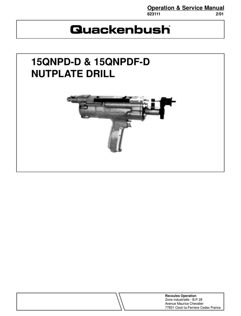
Quackenbush 230QGDA Series Quick guide

For additional product information visit our website at http://www.apextoolgroup.com
Parts Manual
823122
06/02/2011
230QGDA Series
In-line & Right Angle Positive Feed Drills


Page 3
EN-823122
February 17, 2004
Quackenbush
Operating and Safety Instructions
Safety Recommendations
For your safety and the safety of others,
read and understand the safety recom-
mendations and operating instructions.
TAPER-LOK FIXTURING:
Customized fixtures are constructed to accept
Taper-Lok Bushing Tips. Advanced Drilling Equipment
tools with the Bushing Tips are inserted into the fixture,
twisted and com-locked into place.
The Bushing Tip’s rapered flanges fit under the
shoulder of the lock screws in the fixture. The Bushing
Tip holds the tool in alignment and absorbs the thrust
and torque of drilling. At the completion of the drilling
cycle, the toolsis/are rotated to unlock, withdrawn from
the fixture and and moved to the next position.
Several different types of Taper-Lok Fixturiing are
available. The following are the most common.
CAUTION / WARNING LABELS:
The labels found on these tools are an esential part of
this product. Labels should never be removed and
should be checked periodically for legibility. Replace
lables when missing or when the information can no
longer be read. Replacement labels can be ordered
Safety, Operation & Service
Lock Liners
Method for mount-
ing to a fixture. A
hole is bored in the
jig to accommodate
the lock liner bush-
ing in position with
the jig.
Direct Mounting
The Serrated Liner
is used in potted or
cast-in-place instal-
lations.
Taper-Lok
Bushing
Direct Mounting
Most common
mounting method
has lock screws
mounted directly
into the fixture
plate. The shank of
the drill bushing tip
fits directly into a
bored hole in the
fixture plate.
Location Data for Taper-Lok Clamp,
Lock Screw and Lock Strip Mounting
Drill Bushing Tool Nose
Tip Series A B Thread (I.D.)
21000 .312 .625 3/4 - 16
22000 .609 .922 1 - 14
23000 .734 1.047 1-1/4 - 12
24000 .859 1.172 1-1/2 - 12
25000 None 1.562 2 - 16
Lock Strip
This method for
closely spaced
holes employes a
lock strip along
each side of the
row of holes in the
fixture plate. The
flanges on the Drill
Bushing Tip lock
unter the extended
edges of the lock
strip.
Taper-Lok
Bushing

Page 4
EN-823122
February 17, 2004 Quackenbush
Operating and Safety Instructions
from the manufacturer. Refer to the appropriate Parts
List Manual for the label numbers and locations.
• Quackenbush drills are designed to operate on
90psig (6.2 bar) air pressure. Excessive air pressure
can increase the loads and stresses on tool parts and
drills, and may result in breakage. The installation of a
filter-regulator-lubricator in the air supply line is
highly recommended.
• Before removing a tool from service or chang-
ing drill bits, make sure the air line is shut off and
drained of air. This will prevent the tool from operating
if the throttle is accidently engaged.
• Cutting tools used with these Quackenbush
drill motors are sharp. Handle them carefully to
avoid injury.
The spindle on right angle positive feed drills retracts
at a much faster rate than it feeds. Care should be
taken to avoid entrapment. Nose pieces usually used
with these drills are generally slotted for visibility and
access to chuck, cutter, and retract stop adjustments.
A spindle guard should be used when operating
tool. Spindle guards in one inch increments are
available to accommodate any length spindle.
Slotted spindle guards are available for tools with
fluid swivels.
Safety, Operation & Service
Caution
Label
Caution
Label
Caution
Label
AS A REMINDER . . . ALWAYS
wear protective equipment.
Personal hearing
protection is recom-
mended when oper-
ating or working
near these tools.
Do not wear loose
fitting clothes, long
hair, gloves, ties or
jewelry when operat-
ing or working near
these tools.
Impact resistant eye
protection must be
worn while operat-
ing or working near
these tools.
For Your Safety . . .

Quackenbush
Major Tool Controls
Page 5
1 Emergency Stop Button
2 Rapid Advance Lever
3 Exhaust Deflector
4 Drill Button
5 Manual Retract Lever
6 Adjustable Depth Stop
7 Retract Collar Stop
8 Signal Valve
9 Throttle Piston
10 Rear Spindle Guard
11 Variable Speed Control
MAJOR TOOL CONTROLS
Safety, Operation & Service
INLINE TOOL
RIGHT ANGLE TOOL
1
1
9
9
4
4
2
2
7
5
5
3
3
6
10
10
11
8
EN-823122
February 17, 2004

“B”
EN-823122
February 17, 2004 Quackenbush
Standard Tool Dimensions
“A”
Page 6
Safety, Operation & Service
1-9/16”
(40mm)
RIGHT ANGLE DIMENSION
IN-LINE DIMENSION
3-3/16”
(81mm)
3-1/8”
(79mm)
2-15/16”
(75mm)
36/64”
(25mm)
1-7/32 - 1-3/32”
(31mm - 28mm)
3-3/8”
(86mm)
1-9/16”- 20 L.H. Internal Thread for
Close Quarter Applications
3-3/8”
(86mm)
20-1/4”
(522mm)
27-3/8”
(695mm)
3-3/8”
(86mm)
9-3/8”
(238mm)
2-1/4”- 20
L.H. Internal Thread
- Standard
2-1/4”- 20
L.H. Internal Thread
- Standard
1-9/16”- 18 L.H. Internal Thread
for Close Quarter
Applications

Safety, Operation & Service
Page 7
EN-823122
February 17, 2004
Quackenbush
Operating and Safety Instructions
AIR SUPPLY:
AIR PRESSURE, HOSES, AND COUPLINGS:
This tool is designed to operate on 90-110 psig (6.2-7.6
bars) supply pressure using a 1/2" hose up to 20 ft. in
length. If additional hose is needed, a 5/8" or larger
diameter hose should be connected to the 1/2" in. hose.
Quick disconnect couplings (if used) should have flow
capacity ratings exceeding 60 SCFM.
LOW PRESSURE:
This drill will shut-off automatically (while drilling or
when retract begins) if the pressure at the tool inlet
drops below 65 psig (4.5 bars). Manual restart is
required. The drill will not continue to run when the
green drill button is released if the pressure at the tool
inlet is low.
HIGH PRESSURE:
This drill shuts off automatically at the end of the retract
cycle. If the pressure at the tool inlet is over 115 psig
(7.9 bars) the tool may continue to retract, jamming the
retract stop collar into the housing cover causing the
tool to either stall or shear the shear pin.
OPERATING INSTRUCTIONS
If the tool has been shipped recently, been in storage,
or repaired, or disassembled; it should be run (without
spindle) through a "Tool Function Check" of functions.
EMERGENCY STOP—Depressing the red emergency
stop button 1will stop the tool, except when the rapid
advance mode is being utilized. Releasing the rapid
advance lever 2will stop the tool.
RAPID ADVANCE—Depressing the rapid advance
lever 2will advance the cutting tool to the work
surface faster than the regular feed rate and stops
advancing forward automatically until the green drill
button 4is depressed. Note: When the rapid
advance lever is depressed, the exhaust deflector 3will
move forward (toward the head) approximately 3/8" and
return to its original position when the lever is released.
DRILLING—Press the green drill button 4firmly and
release it to start the drilling cycle. The cutter will feed
to a predetermined depth, dwell, and then retract.
The drill motor will shut off automatically at the end of
the retract stroke. The cutter may be manually retracted
at any time by raising the retract lever 5.
IMPORTANT: The spindle retracts at a much faster
rate than it feeds. Care should be taken to avoid
entrapment.
Do not hold the drill button down during the end of the
retract stroke—this prevents "motor stop".
DEPTH ADJUSTMENT:
DEPTH COLLAR—Has four (4) holes for adjusting
depth in increments of .005". Removing the set
screw and rotating the collar about 1/16 revolution
or 22.5° will either increase (clockwise) or decrease
(counterclockwise) the depth by .005". This will align
one of the four holes with one of the four slots. Lock set
screw into a spindle slot. Using the same hole and
rotating the collar 90° will give an adjustment of .020"
and 360° will give an adjustment of .080". Tighten lock
screw after each depth adjustment. IMPORTANT
NOTE: To insure maximum repeatability, the work
surface, fixtures, and depth stop must be cleared of any
chips or foreign material before beginning the next hole.
Always replace the rear spindle guard after making a
depth adjustment.
TOOL FUNCTION CHECK
1. With air supply shut off, remove rear
spindle guard.
2. Remove depth stop 6(left hand threads).
WARNING: Keep hands and clothing clear of
rotating spindle, turn air supply on and use rapid
advance to remove spindle.
3. Shut off air supply pressure.
4. Depress 5/16" diameter steel end of throttle
piston 9. The throttle piston must spring return
quickly when released.
5. With air supply on, move rapid advance lever 2all
the way. Motor runs and spindle feed gear (thread
ed I.D.) must not rotate. Spindle drive gear (splined
l.D.) rotates. Shear pin is whole and intact.

Safety, Operation & Service
Page 8
EN-823122
February 17, 2004 Quackenbush
Operating and Safety Instructions
6. Release rapid advance lever 2and press green
drill button 4all the way in. Motor starts. Release
drill button 4. Motor continues to run. Both gears
(splined and threaded) rotate.
7. Lift manual retract lever 5and release.
An audible "snap" indicates the retract valve
382333 is shifting as desired. Spindle feed gear
(threaded l.D.) stops rotating.
8. Depress signal valve 8with screwdriver and
release. Motor stops and retract valve 382333
must reset (manual retract lever 5should drop).
Depress red stop button 1 slowly. There should
be no venting of air as the stop button
1is depressed.
9. The lift arm assembly 382665 must be intact,
undamaged, and in place in the upper block.
The lift arm assembly is factory adjusted (new
tool) for little or no play.
10. Press green drill button 4and release. Motor
starts. Press stop button 1. Motor stops.
Do not proceed with test if steps 1through 10
indicate malfunction.
11. WARNING: Keep hands and clothing clear of
rotating spindle. Using tool 382593, install spindle
(with retract stop collar 7locked in place).
The spindle will retract fully into the head and the
motor will stop automatically. The retract valve
382333 must reset (manual retract lever 5
should drop) and there should be no venting of air
when the stop button 1is depressed.
12. Screw depth stop 6(left hand threads) onto the
rear end of the spindle and lock in place. Rapid
advance until depth stop 6bears against
back of drill head. Rapid advance clutch will
"chatter". Manual retract lever 5must not rise as
clutch "chatters". Release rapid advance lever.
13. Depress green drill button 4and release.
Motor starts. Retract lever 5rises and spindle
retracts automatically to full retract position.
Motor will stop automatically.
14. Replace rear spindle guard.
INSTALLING A SPINDLE:
Run a "Too Function Check" (page 7)
Important: Retract stop collar 2382579 must be in
place and locked on the spindle. Install the spindle in
the spindle drive gear 617200 and use spindle "in &
out" tool 382593 to push the spindle "in". Depress the
green drill button to start the motor and raise the man-
ual retract lever 5. The spindle will retract. Release the
drill button. The spindle will continue to retract until the
retract stop collar 7depresses the signal valve 8and
the tool will automatically shut off. Note: When the
retract stop collar 7is near or touching the signal valve
8; Do not press the green drill button 4; as this will
prevent tool shutoff and jam the spindle into the head.
CHANGING FEED GEARS—Remove (left hand
threads) the adjustable depth stop 6from the rear of
the spindle. Using the spindle "in & out" tool 382593 to
support the front of the spindle, depress the rapid
advance lever 2and feed the spindle forward until the
spindle feeds itself out of the spindle feed gear.
Release the rapid advance lever, shut off the air sup-
ply, and pull the spindle out of the spindle drive gear.
Remove the side hose assembly. Unscrew and
remove one (1) 6-32 x 1 (7164" hex) socket head cap
screw 382539 and two (2) 1/4-20 x 2-1/4 (3/16" hex)
socket head cap screws 867839 Note: Clamping the
tool in a vise will make removal of the screws more
convenient. Insert finger in spindle feed gear to pre-
vent the eighteen (18) 7/32" balls 842160 from being
lost when removing upper block assembly and spindle
feed gear. Remove differential feed gear. Remove
gear holder 382557. Refer to the feed chart on assem-
bly drawing for the appropriate feed gears. The feed
gears are marked with the number of teeth each one
has — example 33T (thirty three teeth). After installing
the replacement gears, be sure that gear holder
382557 is aligned and in place. The right angle head
should be securely clamped in the vise and
compressed so that the two (2) cap screws 867839
and cap screw 382539 can be firmly tightened.
SHEAR PIN MAY SHEAR BECAUSE:
1. Motor doesn't stop at full retract, or the retract
valve did not reset. Retract collar 7jams into
housing cover 382582 or 382591. Pin shears.

Safety, Operation & Service
Page 9
EN-823122
February 17, 2004
Quackenbush
Operating and Safety Instructions
2. Packed chips or dull cutter may overload the
spindle. Feed rate may be too high. Drilling or
reaming may be beyond the torque capability of
this right angle drill. Pin shears.
3. Improper adjustment of lift arm assembly may
prevent automatic retract when the depth stop 6
contacts the drill head. If this occurs possible
damage to gears and shearing of pin will result.
4. Gear teeth have broken, spindle threads have
been damaged, or parts inside the drill head
have failed.
DOES NOT REQUIRE DISASSEMBLY:
1. Does not require disassembly of drill head, spindle
may be freed in this manner:
A. Turn off air supply.
B. Remove tool from drilling fixture.
C. Rotate spindle with wrench (CCW from
rear). . . opposite drilling direction 2 or 3
turns. This will require high torque.
D. When spindle is free, replace shear pin.
Leave the pin guard in place. Supply air
pressure and rapid advance the spindle out
of the drill head.
E. Correct malfunction and run
"Tool Function Check".
2. Turn off air supply.
A. Remove tool from drilling fixture.
B. Correct torque overload problem.
C. Replace shear pin.
D. Make sure the pin guard is in good condition
and in place.
E. Return tool to service.
3and 4require disassembly, cleaning, inspection, and
replacement of damaged parts inside the drill head.
All parts inside the drill head should be washed and
re-greased. When cause of malfunction is corrected,
run "Tool Function Check" (page 0).
SHEAR PIN INSTALLATION AND REMOVAL
CHANGING RAPID ADVANCE CLUTCH SPRING:
Unscrew and remove the clutch cover 382537. Drive
the shear pin out of the driven gear 382474 and clutch
shaft 382525. Remove clutch assembly from right angle
head. Clamp the clutch assembly in the vise to remove
the spring load before driving the roll pin 415019 out of
the lower clutch jaw 382535. Remove from the vise and
slip the clutch shaft 382525 out of the pinion and clutch
hub 382526.
CHANGING THRUST PACKAGE: Remove the upper
block assembly following the instructions for changing
feed gears (place finger into the spindle feed gear to
keep the eighteen (18) balls from falling out). Remove
the feed gear and eighteen (18) balls. Clamp the spring
case 382663 and upper block assembly in the vise to
compress the thrust package. Use a 7/32" hex wrench
to remove the two (2) 1 0-32 x 1/4" set screws 382637.
Remove the assembly from the vise and slip the spring
case and thrust package out of the upper block.
REASSEMBLY:
Turn the two (2) set screws 382637 in until the tips are
nearly flush with the bore (must clear spring case).
Place one bead of thread locking liquid on outer thread
of each set screw. Using a vise (or similar device), align
the spring case (with Belleville washers inside) and
compress somewhat, until the 5/32" dia. spotface is in
the position shown. Tighten each set screw 1-1/2 turns,
and remove from vise. Set screws should retain spring
case; but allow spring stack to compress and "spring
back".
Note: Milled slot on top rim of spring case must be
visible thru cast window in the upper block.
INSTALL REMOVE
Cast
Window
Spacer
5/32 Spot Face

Safety, Operation & Service
Page 10
EN-823122
February 17, 2004 Quackenbush
Operating and Safety Instructions
Note: Spring washers must be stacked exactly as
shown. A spacer may be included in the spring stack
and must be installed under the bottom washer
against the spring case. Align the bore of the spring
washers to clear the 7/8" O.D. of the spindle.
LUBRICATION:
An automatic in-line filter-lubricator is highly
recommended. This will supply the tool with clean,
lubricated air; keep it in sustained operation; and
increase tool life.
The in-line lubricator should be regularly checked and
filled with a good grade of 10W machine oil. In the
event an in-line lubricator is not used, the tool should
be disconnected from the air supply several times
daily and several drops of oil poured into the tool's air
inlet bushing.
The right angle drill head should receive a generous
amount of "Lubriplate #907" grease every fifteen (15)
to twenty-five (25) hours of "actual motor running"
time through the two (2) flush type grease fittings in
the right angle housing. "Lubriplate # 907" may be
purchased in a 5 gallon can using Part No. 107210.
GENERAL MAINTENANCE:
Tool Maintenance and Pressure Test Equipment
Kit 381273 is available and can be used for some
trouble shooting.
Air control system filter 382505 located in the handle
382480 should be replaced every 2000 drilling cycles
or when low air control system pressure is suspected.
Spindle threads should be blown clean and lubricated
every 100 drilling cycles.
DISASSEMBLY—DRILL HEAD:
Remove the side hose assembly. Clamp the drill head
in vise and loosen lockring 619421. Unscrew and
remove power unit. Remove shear pin. Unscrew one
(1) 6-32 x 1 (7/64" hex) socket head cap screw
382539 and two (2) 1/4-20 x 2-1/4 (3/6" hex) socket
head screws 867839. Clamp drill head in upright posi-
tion in vise. Insert finger in spindle feed gear to pre-
vent the eighteen (18) 7/32" balls 842160 from being
lost when removing upper block assembly. Remove
upper block assembly. Remove gear holder 382557.
Unscrew the two (2) 1/4-20 x 7/8 (3/1 6" hex) socket
head cap screws 865123 and remove the housing
cover 382582 or 382591. Gears will come out with
housing cover.
DISASSEMBLY—GEAR TRAIN:
SINGLE REDUCTION—Unscrew and remove the
lock ring 619421. Clamp the flats of the internal gear
case 382590 in the vise and unscrew the motor hous-
ing 382509. Remove the spider assembly from the
gear case. Remove the rear ball bearing 613281.
Remove the three (3) idler gear pins and gears. Hold
a large hex wrench or similar tool on the side of the
spider and clamp in the vise. Heat the spider and
bevel pinion to approximately 300°F. Insert a suitable
pin thru the hole in the pinion 382461 and unscrew the
pinion. Use Tool Maintenance and Pressure Test
Equipment Kit 381273 for easier disassembly.
DOUBLE REDUCTION—Unscrew and remove the
lock ring 619421. Clamp the flats of the internal gear
case 382590 in the vise and unscrew the motor hous-
ing 382509. Unscrew and remove the internal gear
and housing 617369. Remove the rear ball bearing
613281 from both spiders. Remove the six (6) idler
gear pins and gears. Hold a large hex wrench or sim-
ilar tool on the side of the second reduction spider and
clamp in the vise. Heat the spider and bevel pinion to
approximately 300°F. Insert a suitable pin thru the hole
in the pinion 382461 and unscrew the pinion. Use
Tool Maintenance and Pressure Test Equipment Kit
381273 for easier disassembly.
FOR VARIABLE SPEED TOOLS,
SEE PAGES 14 - 17
DISASSEMBLY—MOTOR UNIT:
Clamp the handle in a vise with the motor housing
upwards. Unscrew both the motor housing 382509
and the turnbuckle collar 382508 in unison from the
handle. Tap motor and motor housing on wooden
bench top to remove motor unit. Hold either the pinion
gear 617609 or rotor nut 382522 and unscrew (left
hand threads) the governor assembly. Remove the
rear bearing 864522, bearing plate 867369, cylinder
867377, and three (3) rotor blades 382520. Note:
Check the function of the rotor blade kickout pins at
this time. Blades should stick out approximately 1/8".

Safety, Operation & Service
If required, the spring cap 382514 must be drilled and
tapped for removal. Clamp the body of the rotor in the
vise and unscrew the pinion 617609 or nut 382522.
Before disassembling the governor, note which
"step" the adjustment ring pin 867187 is "on" in the
adjustment ring 867214. Depress the adjustment ring
and remove the pin. Remove the pin retainer 864532
and remove the two (2) governor weight pins 867184.
DISASSEMBLY—MOTOR BACKHEAD
Important Note: Pressure cap 382507 must not be
unscrewed while the motor backhead is connected to
air supply. This cavity is supplied with high pressure
air whenever the backhead is connected to the air
system. Remove pressure cap, spring 864681, ball
812156, and pin 847031. Rapid advance valve
382501 may be removed by unscrewing valve cap
382502 and removing retainer ring 869460. The rapid
advance lever 382503 may be removed by unscrew-
ing (3/16" hex) the flat head cap screw 382504.
DISASSEMBLY— HANDLE
Unscrew plug 864387 and remove drill button spring
622833. Depress the drill button 382484 and use a
1/8" diameter rod to unscrew button guard 382671.
Unscrew inlet bushing 867758 and remove spring
863072 and throttle valve 202365.
Unscrew end cap 382668 and spring 382489. Push
out throttle piston 382677.
Screw a 1/4-20 cap screw into the metering seat
382491. Clamp the cap screw in the vise and use a
soft faced hammer to drive the handle off.
Filter 382505 located in 13/32" dia. hole adjacent
to the metering seat should be checked and replaced
if necessary.
The emergency stop button 381243 should not be
removed unless the O-ring 844301 needs replacing.
Clamp the stop button in the vise and use a soft faced
hammer to drive the handle off. Tap the bushing
202354 with a 1/4-20 thread. Screw a 1/4-20 bolt in
the vise. Drive the handle off.
Unscrew the check valve seat 382487 and remove
O-ring 844302, 3/16" steel ball 842161 and check
valve spring 382488. NOTE: Spring is very small.
FOR VARIABLE SPEED TOOLS,
SEE PAGES 14 - 17
REASSEMBLY— GENERAL
The tool is reassembled in the reverse order of
disassembly. Clean all parts thoroughly in a solvent
and inspect for damage or wear. Check all bearings
for wear which can be detected by excessive end play
and/or roughness which would indicate a brinelled
condition. Inspect and replace any O-ring that is
damaged or worn. Rotor blades should be replaced at
every repair cycle or if they measure less than 1/4"
(6.35mm) at either end. All gear teeth, bearings, and
pins should receive a close inspection and be
replaced if necessary.
All gears and bearings in the planetary gear train
should receive a generous amount of NLGI 2-EP
grease during reassembly.
All gears and bearings in the right angle drill head
should receive a generous amount of "Lubriplate #
907" grease during reassembly.
Lubricate all O-rings during reassembly with 10W
machine oil.
HANDLE REASSEMBLY:
Insert throttle piston 382677 (with O-rings) into throttle
piston cylinder 382676. Replace spring 382489 and
end cap 382668.
Rotate the throttle piston 382677, to line up the slot
for the throttle valve 202365. Replace spring 863072,
O-ring, and inlet bushing 867758. If the screen in
the inlet bushing is torn or clogged, replace the
inlet bushing.
Page 11
EN-823122
February 17, 2004
Quackenbush
Operating and Safety Instructions

Safety, Operation & Service
Insert spring 382489, O-ring 844307, and latch piston
382490, into handle. Line up the air ports in the
metering seat 382491, and handle 382480, and tap
the metering seat into the handle until the shoulder on
the seat is flush with the surface of the handle. Use a
1/4-20 bolt to tap or press the metering seat. Install the
drill button and shaft assembly 381171, using a thread
retaining compound. Install the drill button spring
622833 and plug 864387 with O-ring.
Press the stop button assembly 381243, into the
handle until the shoulder on the bushing is flush with
the handle.
When installing the check valve assembly, the spring
382488, should be installed with the small coil up. Use
a slender rod. Place the 3/16" steel ball 842161, on
the small coil and the O-ring 844302, on the top of the
ball. Install the check valve seat 382487, and O-ring
844303, and tighten firmly.
MOTOR BACKHEAD REASSEMBLY:
Install rapid advance valve 382501, muffler plate
382506, and retainer ring 869460. Put on muffler
869850, exhaust deflector 869844, and valve cap
382502. Fit rapid advance lever 382503, into detents
and tighten flat head screw 382502, tight.
Place 9/32" steel ball 812156 in 25/64" dia. hole and
rap with a soft metal punch to form aluminum seat.
Be certain that pin 847031 moves freely in hole.
Install pin, ball, spring 864681, and pressure cap
382507.
FOR VARIABLE SPEED TOOLS,
SEE PAGES 14 - 17
MOTOR AND GOVERNOR REASSEMBLY:
Assemble governor and pin retainer 864532. Seat the
front rotor bearing 842870, in the front bearing plate
382521, and support the bearing on its outer race.
Measure from the face of the bearing plate to the
bearing inner race. Select or fit by sanding a rotor
collar .002" longer than this measurement. Install the
rotor collar (chamfered side first) and bearing plate
assembly on the rotor. Tighten rotor pinion 617609,
or rotor nut 382522, to approximately 35 ft. Ibs.
(47.5 Nm). When installing the rotor blades 382520,
be certain that the rotor blade kick-out pins are
working. Assemble the three (3) rotor blades, cylinder
867377, rear bearing plate 867369, rear bearing
864522, and governor assembly. Be certain pin
retainer 864532, is in place. Tighten (left hand
threads) the governor assembly or rear rotor nut
382523, almost as tight as the pinion gear or front
rotor nut.
FOR VARIABLE SPEED TOOLS,
SEE PAGES 14 - 17
MOTOR HOUSING AND RUNNING MOTOR:
Work the motor unit into the housing and clamp the
housing in the vise with the governor assembly up.
Work the muffler element 382517, into the exhaust
deflector 382516. Assemble the O-ring 864589, onto
the turnbuckle collar 382508. Place spring 619394,
on motor housing 382509, and work the exhaust
deflector on, compressing the spring. Screw (left
hand threads) the turnbuckle collar on until the
3/32" dia. hole in the front of the exhaust deflector is
half covered.
Screw the motor backhead onto the motor housing
(prevent turnbuckle rotation), clamping the motor unit
securely. Use two (2) 1/4-20 cap screws and wooden
hammer handle to tighten the motor backhead.
Install gasket 382492, and handle 382480, on the
backhead—16 ft. Ibs. (21 .7 Nm) minimum. Be sure to
include filter 382505.
Page 12
EN-823122
February 17, 2004 Quackenbush
Operating and Safety Instructions
.002” Gap after Assembly
3/32” Diameter

Safety, Operation & Service
Temporarily plug the 1/8 NPT port in the motor
backhead with a pipe plug.
Invert unit and clamp in vise on the handle flats with
motor gear up.
NOTE: The exhaust deflector moves forward
approximately 3/8" when rapid advance lever
is depressed.
Apply 90 PSI air to the inlet bushing. Do not press drill
button. Operate the rapid advance lever and release,
several times. The 9/32" dia. steel ball should seat
without leakage, and there should be little or no slack
in the lever. Pin 847031 may require hand grinding to
proper length. Make certain the air supply is shut off
and drained before removing pressure cap 382507.
If the pin is too short, get a new pin and resize.
Tighten pressure cap securely.
It does not matter whether the rotor has been turning
or not; but the following method should get the motor
running with the least chance of rubbing.
Place wrenches on the motor housing hex and the
turnbuckle collar flats rotating them together to loosen
the threaded joint between the turnbuckle collar and
the motor backhead 1/4 turn.
Put a few drops of 10W machine oil into the inlet
bushing and apply 90 PSI air pressure to the motor
unit. Press the drill button. The motor should run
forward at governed speed. Then using both
wrenches, tighten the motor housing and the
turnbuckle collar in unison to securely clamp the
motor unit.
Adjust governed speed when needed by removing the
motor backhead and rotating the governor adjusting
ring 867214. Rotate clockwise to decrease the R.P.M.
and counterclockwise to increase the R.P.M. setting.
Reverse rotation (rapid advance lever depressed)
should be 5,700 R.P.M. minimum.
RIGHT ANGLE TOOLS
Desired forward rotor speeds (R.P.M.)
INLINE TOOLS
Desired forward rotor speeds (R.P.M.)
Page 13
EN-823122
February 17, 2004
Quackenbush
Operating and Safety Instructions
Drill Spindle Rotor Speed
R.P.M R.P.M.
50 5,800 - 6,200
65 7,200 - 7,760
80 8,870 - 9,400
100 11,300 - 12,100
125 7,100 - 7,500
160 8,900 - 9,350
205 11,100 - 12,200
260 6,900 - 7,450
320 8,600 - 9,100
390 10,200 - 11,100
440 11,600 - 12,400
550 7,400 - 7,900
640 8,600 - 9,130
770 10,200 - 11,100
1,000 13,000 Min.
Drill Spindle Rotor Speed
R.P.M R.P.M.
75 5,800 - 6,200
100 7,200 - 7,760
120 8,870 - 9,400
150 11,300 - 12,100
190 7,100 - 7,500
240 8,900 - 9,350
310 11,100 - 12,200
390 6,900 - 7,450
480 8,600 - 9,100
585 10,200 - 11,100
660 11,600 - 12,400
825 7,400 - 7,900
960 8,600 - 9,130
1,165 10,200 - 11,100
1,500 13,000 Min.

Safety, Operation & Service
Page 14
EN-823122
February 17, 2004 Quackenbush
Operating and Safety Instructions
VARIABLE SPEED TOOLS
For disassembly of drill head and gear trains, see page
14-17.
DISASSEMBLY—VARIABLE SPEED MOTOR AND
GOVERNOR UNIT
Clamp handle in vise with motor housing upwards.
Unscrew both motor housing 382509 and turnbuckle
collar 382508 in unison from handle. Keep governor
center 382619, shims, and bearing 847095 together as
a unit. Replace this bearing if it is damaged.
CAUTION: Do not lose these shims. The same shims
must be used for reassembly.
Tap motor and motor housing on wooden bench top to
remove motor unit. Hold either the pinion gear 617609
or rotor nut 382522 and unscrew (left hand threads)
governor assembly. Remove rear bearing 864522,
bearing plate 867369, cylinder 867377 and three (3)
rotor blades 382520. Note: Check function of rotor
blade kick-out approximately 1/ 8". If required, the
spring cap 382514 must be drilled and tapped for
removal. Clamp body of the rotor in vise and unscrew
pinion 617609 or nut 382522. To remove governor
weights from spider, press governor weight pins
867184 out.
DISASSEMBLY—VARIABLE SPEED
MOTOR BACKHEAD
WARNING: Pressure cap 382507 must not be
unscrewed while the motor backhead is connected to
air supply. This cavity is supplied with high pressure air
whenever the backhead is connected to the
air system.
Remove pressure cap, spring 864681, ball 812156, and
pin 847031. Rapid advance valve 382501 may be
removed by unscrewing valve cap 382502 and
removing retainer ring 869460. The rapid advance lever
382503 may be removed by unscrewing (3/16" hex) flat
head cap screw 382504. Remove button head
screw 844288. That will release the governor valve
382618. Remove governor spring 382238, shims
202349, auxiliary spring cap 382264, spring 382271
(inside cap) and guide stud 382620. Caution: Do not
lose those shims. The same shims must be used
for reassembly. Remove set screw 382512 and
speed cam. Remove detent pad 382627, set screw
867502, and spring 512275 for inspection.
DISASSEMBLY—HANDLE Same as on page 14.
REASSEMBLY—GENERAL Same as on page 14.
REASSEMBLY—HANDLE Same as on page 14.
REASSEMBLY—VARIABLE SPEED MOTOR
BACKHEAD
Install rapid advance valve and related parts (same as
single speed tool). Lubricate O-ring 844307 on speed
cam. Assemble spring 512275, set screw 867502, and
detent pad 382627 onto backhead. Install speed cam
and lock set screw 382512. Install governor parts in
reverse order of disassembly and secure with button
head screw.
REASSEMBLY—VARIABLE SPEED MOTOR AND
GOVERNOR
Assemble governor weights 867189, pins 867184, and
spider 382621. Seat front rotor bearing 842870, in front
bearing plate 382521, and support bearing on its outer
race. Measure from face of the bearing plate to bearing
inner race. Select or fit by sanding a rotor collar .002"
longer than this measurement. Install rotor collar
(chamfered side first) and bearing plate assembly
on rotor. Tighten rotor pinion 617609, or rotor nut
382522, to approximately 35 ft. Ibs. (47.4 Nm).
When installing the rotor blades 382520, be certain that
the rotor blade kickout pins are working. Assemble the
three (3) rotor blades, cylinder 867377, rear bearing
plate 867369, rear bearing 864522, and governor
assembly. Tighten (left hand threads) governor
assembly almost as tight as pinion gear or front
rotor nut.
VARIABLE SPEED MOTOR HOUSING AND
RUNNING MOTOR
Work the motor unit into the housing and clamp the
housing into a vise with the governor assembly upward.
Assemble the governor center 382619, shims, and
bearing 847095, with the governor weights leaning
inward.

Safety, Operation & Service
RIGHT ANGLE TOOLS
Set the speed adjustment to one of these settings:
80 RPM (125V)
160 RPM (250V)
320 RPM (520V)
650 RPM (1000V)
INLINE TOOLS
Set the speed adjustment to one of these settings:
125 RPM (190V)
240 RPM (375V)
480 RPM (780V)
900 RPM (1500V)
REASSEMBLY—MOTOR HOUSING AND
RUNNING MOTOR
Same as on page 14.
DESIRED FORWARD ROTOR SPEED
At the selected speed setting (80, 160, 320, or 650) the
rotor speed should be 8200 - 9700 RPM.
The motor speed should change smoothly as the speed
is adjusted step by step.
Reverse rotation (rapid advance lever depressed)
should be 5,700 RPM minimum.
If shims are lost, or rotor speed is improper, remove
motor unit and clamp in vise with the governor
assembly upward and the governor weights leaning
inward. Add or adjust shims 864732 and 869562 to
provide this clearance:
Reassemble and run motor. If the desired forward rotor
speed is still not acceptable (8200 - 9700 RPM); disas-
semble motor backhead and add shims 203349 under
governor spring 382238 to increase speed, or remove
shims to decrease speed.
Continue reassembly same as single speed tools
FINAL REDUCTION ASSEMBLY:
Reassemble in the reverse order of disassembly.
Grease all parts with a good grade of NLGI 2-EP
grease. Install the washer and ball bearing 864471 on
the front of the output spider. Clean the threads on the
spider and pinion gear 382461. Hold a large hex wrench
or similar tool on the side of the spider and clamp in the
vise. Apply a thread locking liquid to the threads and
screw the pinion into the spider (tighten to approxi-
mately 60 ft. Ibs.—81.4N). Use Tool Maintenance Kit for
easier assembly.
HEAD REASSEMBLY:
UPPER BLOCK: The retract valve must slide
freely (without O-ring) by its own weight inside the bore.
Lubricate and assemble O-ring 844306, retract valve
382333, spring 382540, and tighten valve cap 382331.
Press (press on the bearings stamped end) the needle
bearing 617253, into the rear of the gear stop 382547.
The bearing should be flush with face. Assemble O-ring
863009, on feed piston 382548 lubricate and fit into
bore. Piston should move with finger tip pressure. Press
the gear stop into bore. Apply a drop of thread locking
liquid on the two (2) screws 812667 and tighten them.
Page 15
EN-823122
February 17, 2004
Quackenbush
Operating and Safety Instructions
.001
.006
864732-3
869562-9
.005
.020
Shims

Screw the two (2) set screws, 382637 in until they are
nearly flush with the bore (must clear spring case).
Place a drop of thread locking liquid on the outer
thread of each screw. Assemble the thrust package as
shown into the spring case. Clamp the spring case
and upper block in the vise, aligning the spring case
and compressing until the 5/32" dia. spotface is in the
position shown. Tighten each set screw 1 & 1/2 turns,
and remove from vise. The set screws should retain
spring case; but allow spring stack to compress and
"spring back".
Note: Milled slot on top rim of spring case must be
visible through cast window in the upper block.
Note: Spring washers must be stacked exactly as
shown. A spacer may be included in the spring stack
and must be installed under the bottom washer
against the spring case. Align the bore of the spring
washers to clear the 7/8" O.D. of the spindle.
RIGHT ANGLE HOUSING —
SHIMMING THE DRIVEN GEAR, NO. 382474.
Assemble the seal 512442 and ball bearing 864471
into the right angle housing 382679.
Measure the O.D. of the bevel pinion 382461 and
record (should be between 1.085" and 1.095").
Use a depth micrometer to obtain dimension B(should
be between 1.482" and 1.500"). Screw in final
planetary reduction and measure from face Fto the
O.D. of the bevel pinion. Add one half (1/2) of the
pinion O.D. measurement to this measurement to
obtain Adimension. Subtract Afrom Bto obtain C.
C Shims Required Part No.
.655" to .659" .005" 863926-2
.660" to .664" .010" 869559-5
.665" to .670" .015"
Unscrew the final planetary reduction. Place required
shims on bevel gear and press gear into bearing.
Set the housing aside.
RAPID ADVANCE CLUTCH (OMIT SHEAR PIN)
INLINE CLUTCH:
Assemble the clutch spring, clutch shaft 632598 pinion
and clutch hub 382526, ball bearing 844966, upper
clutch jaw 382536, lower clutch jaw 382535.
Compress in vise and install roll pin 415019. Remove
from the vise and drive pin to central position. Press
bearing 812219 into cap 382537.
RIGHT ANGLE CLUTCH:
Assemble the clutch spring, clutch shaft 382525 pinion
and clutch hub 382526, ball bearing 844966, upper
clutch jaw 382536, lower clutch jaw 382535.
Compress in vise and install roll pin 415019. Remove
from the vise and drive pin to central position.
Safety, Operation & Service
Page 16
EN-823122
February 17, 2004 Quackenbush
Operating and Safety Instructions
Measure
.652
Desired
A
C
F
B
Cast
Window
5/32 Spotface
Spacer

Safety, Operation & Service
Page 17
EN-823122
February 17, 2004
Quackenbush
Operating and Safety Instructions
SHIMMING BEVEL PINION, NO. 382461.
Place housing cover 382582, or 382591 on right angle
housing and secure with two (2) cap screws 865123.
Place .040" of shims into R. A. housing and screw in
final planetary assembly snugly against shims. Use an
empty motor housing or empty internal gear case to
clamp the final planetary in place.
Insert the rapid advance clutch assembly and tighten
clutch cover 382537 lightly. Using a punch or rod
through the shear pin hole, the bevel gear 382474
should rotate freely without interference with the bevel
pinion 382461. Loosen and remove .005" or .010"
shims one at a time and retighten final planetary.
When a definite resistance to gear rotation is felt,
add one (1) .010" shim and retighten securely (40 ft.
Ib.— 54.2 Nm minimum) using the flats on the motor
housing or internal gear case. Tighten the lock ring
619421 firmly with a spanner wrench and unscrew the
motor housing 382509, if used.
Internal gear and housing 617369 may be left in place,
if used. Remove the clutch cover, clutch assembly and
housing cover.
HOUSING COVER ASSEMBLY:
Place the retract piston 382550, two (2) O-rings
863009, spring 864681, and cylinder plug 382552,
into housing cover, 382582, or 382591 (lubricate with
10W oil) and install retainer ring 619017. Use Tool
Maintenance Kit (823170).
Press the idler gear shaft 617208 through the cover
until the shoulder is 13/16" above the surface of the
cover. Install ball bearing 617220 and spindle drive
gear 617200 in the cover. Place one (1) spacer
843390 on each of the two (2) gear shafts on the
cover. Press two (2) ball bearings 619019 on the idler
gear shaft 617208. Recheck the 13/16" dimension and
reset if necessary. Install retainer ring 619017 in idler
gear 382527 and assemble over ball bearings. Install
ball bearing 619377 and differential drive gear
382545. Install signal valve assembly and tighten cap
screw 863337.
Grease two (2) O-rings 844301 and place one (1) in
machined pocket in housing and the other in
machined pocket in cover. Use grease to hold gear
spacer 613687 in place. Align one (1) notch in spacer
with pin in head. Place assembled housing cover on
housing and snug up two (2) cap screws 865123.
FINAL HEAD REASSEMBLY:
Place eighteen (18) balls 842160 in spring case
382663 with grease.
NOTE: The eighteen (18) balls 842160 should be
replaced if there is any indication of roughness. Place
spindle feed gear inside balls and install in housing.
Align and install gear holder 382557.
IMPORTANT: The tang (hooked end) on the gear
holder must be installed in the head first and the tang
should be between the differential drive gear, 382545,
and differential feed gear. Place differential feed gear
in housing. Grease two (2) O-rings 844301 and place
in machined pockets in upper block, and assemble
upper block to housing. Clamp head in vise and
compress. Firmly tighten two (2) cap screws 867839
and one (1) cap screw 382539 on the upper block and
two (2) cap screws 865123 on the housing cover.
Insert clutch assembly, shear pin, and install pin guard
and clutch cover.
Install spring 843259, retract lever 382544, and
fulcrum screw 382512 in the upper block. Assemble
the lift arm assembly 382665, pivot plate 382667, and
two (2) cap screws 612789 on the upper block. Use a
thread locking liquid on the threads of the slack adjust
screw 382666 and adjust the screw until the lift arm
touches (but does not lift) the retract lever 382544.
FINAL ASSEMBLY:
Assemble planetary gear cases (complete with all
gears) onto R.A. head and tighten securely using flats
on motor housing 382509. Place tool in vise with inlet
bushing down and clamp vise jaws on handle 382480
flats. Loosen turnbuckle 382508 and motor housing in
unison CCW 1/4 turn. By adjusting turnbuckle and
13/16”
Press

Page 18
EN-823122
February 17, 2004 Quackenbush
Operating and Safety Instructions
Safety, Operation & Service
tightening (CW) flats on motor housing 382509 posi-
tion R.A. head in desired location and tighten (CW)
flats on motor housing securely
Remove 1/8" NPT pipe plug (installed temporarily)
from the motor backhead. Install right angle fitting
382664 pointing forward when tight. Install side hose
assembly 382674 (long) or 382673 (short).

Safety, Operation & Service
Page 19
EN-823122
February 17, 2004
Quackenbush
Operating and Safety Instructions
SOLID SPINDLES AND GUARDS
GUARD CAP - 624359 (1)
SPINDLE GUARD
382390 624397
382628 6”
382391 624500
7”
382617 624398
382708 8”
382349 624399
382616 9”
382631 624402
623853 13”
382639 624403
15”
FLUID SPINDLES AND GUARDS
GUARD CAP - 624359 (1)
GUARD SHIM (.010) - 624358 (2)
SPINDLE GUARD
624404
4”
382373 624505
5”
624405
6”
382346 624406
382599 7”
382614 624407
8”
382607 624408
623856 9”
382554 624409
382636 10”
382661
382605 624506
11”
624410
12”
382399 624411
382555 13”
382371 624502
623855 14”

Page 20
EN-823122
February 17, 2004 Quackenbush
Operating and Safety Instructions
In-Line & Right Angle Accessories
230QGDA SERIES
Depth and Dwell Attachments
(Used in In-Line and Right Angle Positive
Feed Tools)
The Depth Control or Countersink Attachment is a
high quality, precision attachment for the 230 Series
Positive Feed Drill which is used to precisely control
the depth drilled and reamed, straight or tapered holes
on both flat or contoured surfaces.
The attachment is also used for precision countersink
operations. This attachment has been proven on the
most demanding hole preparation jobs in the aircraft
industry, and has earned the reputation for producing
exceptionally high quality holes with precise depth
accuracy, roundness and high level of finish.
HOW THE DEPTH AND DWELL ATTACHMENT
OPERATES.
START.
Threaded to the end of the Depth and Dwell
Attachment is a DRILL BUSHING 3which is used to
secure the unit to the tooling fixture 2. A tubular
SENSING SLEEVE 6is piloted by and slides axially
inside the DRILL BUSHING 3. The SENSING
SLEEVE surrounds and pilots the CUTTER 7and
the SPINDLE 8. It is SPRING 4biased to the
WORKPIECE 1and seat against it 5. The primary
function of the SENSING SLEEVE is to provide a
positive, definite stopping surface that is a precise
repeatable distance from the workplace.
FINISH.
Attached to SPINDLE 8 is a patented micrometer
type, ADJUSTABLE ROTATING STOP 9 with a self-
contained anti-friction bearing designed to engage the
SENSING SLEEVE when the CUTTER has achieved
the desired depth.
Once the pre-determined depth has been reached, the
advancement of the CUTTER is stopped by the
engagement of the ADJUSTABLE STOP on the SPIN-
DLE contacting the SENSING SLEEVE. This allows
the CUTTER to dwell (continue rotation with further
feed) and produce the desired hole characteristics
The Model 230 Drill (furnished under separated order)
features automatic thrust activated retract, torque
overload shear pin, and automatic motor stop after
retract.
When mounted on the Model 230 Positive Feed Drill,
the common SPINDLE 8 extends through and is
driven by the right angle drill head.
Spindles (up to 15” long) will be hollow for coolant
flow. A fluid inducer (Part No. 381213) may be
purchased for the remote end of the spindle.
Rear spindle guards must be used on all applications.
NOTE: Models designed for 1.186 maximum diameter
cutters are available. Shortened models are available
for short strokes in confined work areas.
Safety, Operation & Service
This manual suits for next models
2
Table of contents
Languages:
Other Quackenbush Drill manuals

Quackenbush
Quackenbush 120QP-21500 Series User manual

Quackenbush
Quackenbush 120SC - 225 Installation and operating instructions

Quackenbush
Quackenbush 230QGDAB Series Installation and operating instructions

Quackenbush
Quackenbush 158QRA Series User manual

Quackenbush
Quackenbush 15QD Installation and operating instructions

Quackenbush
Quackenbush 15QNPD-D Installation and operating instructions