rancho suspension RS6502 User manual

INSTALLATION INSTRUCTIONS 88029
REV B
FOR SUSPENSION SYSTEMS RS6502 & RS6503: JEEP WRANGLER (TJ)
READ ALL INSTRUCTIONS THOROUGHLY FROM START TO FINISH BEFORE BEGINNING
INSTALLATION
IMPORTANT NOTES!
A. The vehicle’s alignment must be within factory
specifications before installing this system. Have
the alignment checked at a state approved facility.
B. Check the frame of the vehicle for any damage or
severe corrosion. If there is any structural damage,
Do Not install this system
C. Do not install a body lift kit with Rancho’s
suspension system or interchange parts from this
system with components from another
manufacturer. Use the appropriate Rancho shock
absorbers. Contact your local Rancho
representative for the correct application.
D. Compare the contents of this system with the parts
list in these instructions. If any parts are missing,
including fasteners, contact the Rancho Technical
Department at 1-800-5SHOCKS. Each hardware kit
in this system contains fasteners of high strength
and specific size. Do not substitute a fastener of
lesser strength or mix one hardware kit with
another.
E. Apply THREAD LOCKING COMPOUND to all
bolts during installation. One drop on the exposed
threads of each bolt before installing the nut is
sufficient to provide an adequate bond. CAUTION:
Thread locking compound may irritate sensitive
skin. Read warning label on container before use.
F. Install all nuts and bolts with a flat washer. When
both SAE (small OD) and USS (large OD) washers
are used in a fastener assembly, place the USS
washer against the slotted hole and the SAE washer
against the round hole.

2
PO BOX 5429 LONG BEACH, CA 90805
∋1-800-574-6257 ∋

3
G. Unless otherwise specified, tighten all bolts to the
standard torque specifications listed at the end of
the note's section. Do not use an impact wrench to
tighten any of these bolts. They tend to over tighten
smaller bolts and under tighten larger bolts. USE A
TORQUE WRENCH!!!
H. Rancho parts come with a protective coating. Do
not chrome, cadmium, or zinc plate any of the
components in this kit, or alter their original finish
in any way. However, you may add a layer of
Enamel paint over the original coating.
I. Do not weld anything to these components, and do
not weld any of these components to the vehicle. If
any component breaks or bends, contact your local
Rancho dealer or Rancho for replacement parts.
J. Some of the service procedures require the use of
special tools designed for specific procedures.
These special tools should be used when
recommended.
K. The following tools and supplies are recommended
for proper installation of this kit. Ρ
Jeep Service Manual
Spring Compressor
Drill Motor
23/64", 15/32", 13/32" and 9/32" Drills
Torque Wrench (250 FT-LB capacity)
1/2” Drive Ratchet and Sockets
Combination Wrenches
Allen Wrenches
Torx Key Sockets
Heavy Duty Jack stands
Wheel Chocks (Wooden Blocks)
Hydraulic Floor Jack
Large "C" Clamps and or Bench Vise
Hammer
Molybdenum Grease or Anti Seize Compound
Silicone Spray
Safety Glasses--Wear safety glasses at all times
L. It is extremely important to replace torsion bars, CV
flanges, and front drive shaft/pinion relationships as
original. Be sure to mark left/right, front/rear, and
indexing of mating parts before disassembly. A
paint marker or light colored nail polish is handy for
this.
M.Suspension components that use rubber or urethane
bushings should be tightened with the vehicle at
normal ride height. This will prevent premature
failure of the bushing and maintain ride comfort.
N. The required installation time for this system is
approximately 8 hours. Check off the box ( Ρ) at
the beginning of each step when you finish it. Then
when you stop during the installation, it will be
easier to find where you need to continue from.
O. Important information for the end user is contained
in the consumer information pack. If you are
installing this system for someone else, display the
information pack by hanging it from the rear view
mirror.
P. Thank you for purchasing the best suspension
system available. For the best installed system,
follow these instructions. If you do not have the
tools or are unsure of your abilities, have this
system installed by a certified technician.
RANCHO IS NOT RESPONSIBLE FOR
DAMAGE OR FAILURE RESULTING FROM
IMPROPER INSTALLATION OF THIS
SUSPENSION SYSTEM.
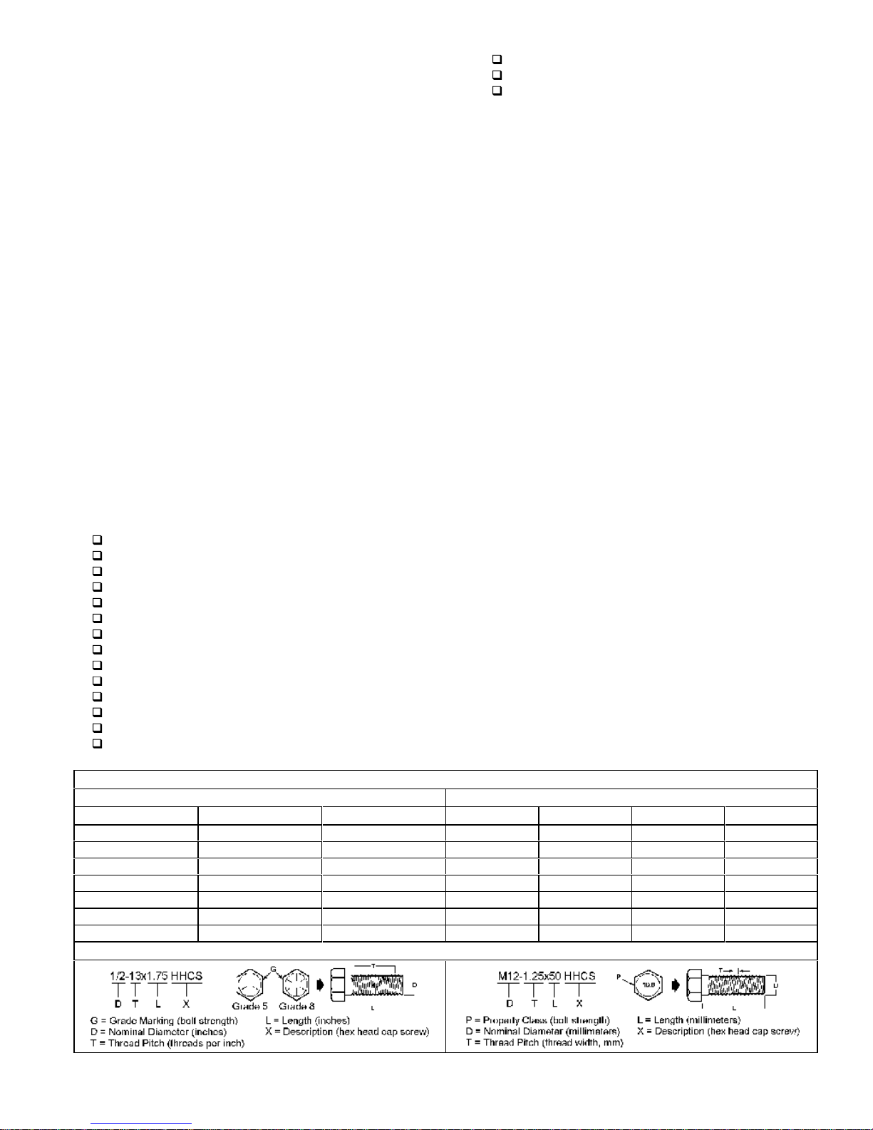
STANDARD BOLT TORQUE SPECIFICATIONS
INCH SYSTEM METRIC SYSTEM
Bolt Size Grade 5 Grade 8 Bolt Size Class 9.8 Class 10.9 Class 12.9
5/16 15 FT-LB 20 FT-LB M6 5 FT-LB 9 FT-LB 12 FT-LB
3/8 30 FT-LB 35 FT-LB M8 18 FT-LB 23 FT-LB 27 FT-LB
7/16 45 FT-LB 60 FT-LB M10 32 FT-LB 45 FT-LB 50 FT-LB
1/2 65 FT-LB 90 FT-LB M12 55 FT-LB 75 FT-LB 90 FT-LB
9/16 95 FT-LB 130 FT-LB M14 85 FT-LB 120 FT-LB 145 FT-LB
5/8 135 FT-LB 175 FT-LB M16 130 FT-LB 165FT-LB 210 FT-LB
3/4 185 FT-LB 280 FT-LB M18 170 FT-LB 240FT-LB 290 FT-LB
BOLT IDENTIFICATION

4
PARTS LIST
P/N DESCRIPTION QTY.
130019 Right Track Bar Bracket 1
1335 Lower Suspension Arm 4
615 Front Coil Spring (RS6503 only) 2
616 Rear Coil Spring 2
618 Front Coil Spring (RS6502 only) 2
8567 Rear Bump Stop Spacer Kit 1
Spacer 2
8597 Bushing/Sleeve Kit 1
Sleeve 8
Bushing 16
860070 Shim Kit 1
Washer 16
860071 Shift Relocation Kit 1
Bracket 1
1/4-20x.75 BHCS 4
1/4 SAE Washer 4
1/4-20 Nyloc Nut 4
Thread Lock 2
P/N DESCRIPTION QTY.
860072 Track Bar Relocation Kit 1
Sleeve 1
7/16-14x1.0 HHCS 1
7/16-14 Stover Nut 1
7/16 SAE Washer 2
M12-1.75x70 HHCS 2
M12-1.75 Nut 2
SAE Washer 4
3/8-16x1.0 HHCS 1
3/8-16 Stover Nut 1
3/8 SAE Washer 2
860073 Skid Plate Spacer Kit 1
Skid Plate Spacer 6
1/2 Cone Washer 6
1/2-13x2.5 FSHCS 6
M10-1.50x70 HHCS 2
10mm Lock Washer 2
88029 Instructions 1
94140 Consumer Information Pack 1

5
LOWER SUSPENSION ARM ASSEMBLY
Bushing & Sleeve Installation
1. ≤Lubricate the outside diameter of two red
urethane bushings, from kit 8597, with a
silicone spray or a mild solution of soap and
water.
2. ≤Press the bushings (Do Not Hammer) into
one end of a new lower suspension arm. See
figure 1.
Figure 1
3. ≤Lubricate the outside diameter of a sleeve,
from kit 8597, and the inside diameter of the
installed urethane bushings.
4. ≤Press the sleeve into the bushings.
NOTE: If necessary, use a bench vise or C-
clamp to press the bushings and sleeves into
the suspension arm. Do not use a hammer.
5. ≤Pre-grease arm assembly with a grease
gun. Make sure not to blow the bushings out
of the assembly. Stop when grease appears
at the end of the bushing grooves.
6. ≤Repeat steps 1 through 5 for the remaining
suspension arm ends, bushings, and sleeves.
FRONT SUSPENSION
Shock & Spring Removal
1. ≤Park vehicle on a level surface, set the
parking brake and chock rear wheels.
2. ≤From inside the engine compartment,
remove the upper stud nut, retainer and
grommet from both front shock absorbers.
3. ≤Raise the front of the vehicle and support
the frame with jack stands.
4. ≤Remove the front wheels.
5. ≤Position a hydraulic jack under the front axle
for support. Remove the stabilizer link lower
nut and bolt from both sides of the front axle.
See Figure. 2
Figure 2
6. ≤Remove the shock absorber lower nuts and
bolts from the axle bracket. Remove both
shocks and discard. DO NOT REUSE
ORIGINAL SHOCK ABSORBERS.
7. ≤Lower axle and remove hydraulic jack.
8. ≤Remove the rubber bump stops and bump
stop mounts.
9. ≤Remove the coil spring retainer bolts and
retainers.
10. ≤Push down on the axle and remove each
coil spring.
Lower Arm Replacement
1. ≤Support the front axle with a hydraulic jack.
2. ≤Paint or scribe alignment marks on the
adjustment cams and axle brackets for
installation reference. See Figure 3.

6
Figure 3
3. ≤If equipped with ABS brakes, remove sensor
wires and clamps from the inboard side of the
lower arms. Save clamps for reuse.
NOTE: Remove and replace one suspension
arm at a time.
4. ≤Remove the nut, cam, and cam bolt from the
axle bracket. Remove the nut and bolt from
the frame bracket. Remove the lower
suspension arm. See Figure 4
Figure 4
5. ≤Install a new Rancho Lower Suspension
Arm, along with four shims from kit 860070, to
the frame and axle brackets. See figure 5.
Use original hardware but do not tighten.
Figure 5
Note: Position the arm so that the grease
fittings are accessible. Also, the cam adjuster
bolt may have to be installed from the
opposite way.
6. ≤Repeat steps 4 and 5 for the other front
suspension lower arm.
7. ≤If applicable, drill a 23/64" hole into each
lower arm and reinstall the ABS sensor wires.
Use the original clamps.
Shock & Spring Installation
1. ≤Lower the front axle and remove the
hydraulic jack.
2. ≤Compress a new coil spring (615 or 618) to
16" in length. Use a quality spring
compressor like the one shown in figure 6.
Figure 6
3. ≤Place the rubber bump stop and bump stop
mount inside the compressed spring. Install
the spring into the upper and lower spring

7
pockets. Carefully remove the spring
compressor.
4. ≤Rotate spring so pig tail end fits back in
spring pocket. Install spring retainer and bolt.
Tighten to 16 FT-LBS.
5. ≤Reinstall bump stop mount and rubber bump
stop.
6. ≤Repeat steps 2 through 5 for other side.
7. ≤Install one retaining washer and grommet
onto each new front shock absorber. Attach
shocks to axle brackets. Tighten bolts to 23
FT-LBS.
8. ≤Install front wheels and lower vehicle to the
ground. Tighten lug nuts to 80--110 FT-LBS.
9. ≤Position shock stud through upper mounting
hole. Install upper shock grommet, retainer
and nut. Tighten to 17 FT-LBS. Repeat for
other side.
10. ≤Reconnect the stabilizer bar to the front
axle. Tighten both lower link bolts to 70 FT-
LBS.
11. ≤Tighten the lower suspension arm to frame
bracket nut and bolt to 130 FT-LBS (both
sides).
12. ≤Align the reference marks on the adjustment
cams and lower arm axle brackets. Tighten
nuts to 85 FT-LBS.
13. ≤Grease new lower suspension arms until
you see a slight amount of grease coming out
of bushings. DO NOT OVER GREASE!!!
REAR SUSPENSION
Shock & Spring Removal
1. ≤Chock front wheels.
2. ≤Disconnect the stabilizer bar links from the
stabilizer bar.
3. ≤Disconnect the track bar from the frame
bracket. See figure 7.
4. ≤Raise the rear of the vehicle and support the
frame with jack stands. Remove the rear
wheels.
5. ≤Separate the track bar from the axle
bracket. Remove the track Bar. See Figure
7.
Figure 7
6. ≤Support the rear axle with a floor jack and
remove the shock absorbers.
7. ≤Mark the orientation of the coil springs on
the axle pads. Carefully lower the rear axle
until the coil springs are free from the upper
mount seat. Remove the coil springs.
Track Bar Bracket Installation
1. ≤Place track bar bracket 130019 on top of the
axle bracket as shown in figure 8. Insert a
14mm bolt through both brackets. Using the
new bracket as a template, mark the two
additional holes on the axle bracket.
Figure 8

8
2. ≤Remove bracket and drill holes. Drill a
13/32" hole through the top of the axle bracket
and 15/32" hole through the side.
3. ≤Reinstall the track bar bracket and attach it
to the axle with the sleeve and hardware from
kit 860072. See Figure 8. Tighten to
specifications.
4. ≤Insert track bar into track bar bracket and
install the 14mm hardware from kit 860072.
Do not tighten.
5. ≤Raise the rear axle and position the track
bar into the frame bracket. Loosely install the
original hardware.
6. ≤Bend gas tank skid plate away from track
bar if necessary.
Lower Arm Replacement
Note: Remove and replace one suspension
arm at a time.
1. ≤Support the rear axle with a hydraulic jack.
2. ≤Remove the lower arm axle and frame
mounting bolts. Remove the lower
suspension arm.
3. ≤Install a new Rancho lower suspension arm,
along with four shims from kit 860070, to the
frame and axle brackets. See figure 9. Use
original hardware but do not tighten.
Figure 9
Note: Install two shims at each mounting
point, one on either side of the bushing
assembly. Also, position the arm so that the
grease fittings are accessible.
4. ≤Repeat steps 2 and 3 for the other side.

9
Bump Stop Spacer & Coil Spring Installation
1. ≤Remove the rubber bump stop and bump
stop bracket from the upper spring mount.
2. ≤Insert a Rancho spacer from kit 8567 and
reinstall the bracket with the 10mm hardware
from kit 860073. See figure 10.
Figure 10
3. ≤Insert the bump stop into the bump stop
bracket. Repeat steps 1 through 3 for other
side.
4. ≤Lower rear axle and position the new coil
springs onto the axle pads. Align springs with
reference marks. Raise the axle until the
spring seats in the upper mount.
Note: When installing coil springs, make sure
that the rubber damper is positioned in the
upper mount and the small egg-shaped coil
end is at the top.
5. ≤Install new Rancho rear shocks to the upper
frame rail. Tighten mounting bolts to 23 FT-
LBS.
6. ≤Attach shocks to the axle brackets loosely.
7. ≤Install wheels and lower vehicle to the
ground. Do not remove wheel chocks.
Tighten lug nuts to 80—110 FT-LBS.
8. ≤Tighten the lower shock mounting bolts and
the track bar mounting bolts to 74 FT-LBS.
9. ≤Reconnect stabilizer bar links. Tighten
nuts/bolts to 40 FT-LBS.
10. ≤Tighten all lower arm mounting nuts to 130
FT-LBS.
11. ≤Grease new lower suspension arms until
you see a slight amount of grease coming out
of bushings. DO NOT OVER GREASE!!!
TRANSMISSION & TRANSFER CASE
Crossmember Relocation
1. ≤Place the transmission in neutral. Support
the transfer case crossmember/skid plate with
a hydraulic jack. Loosen the 6 bolts holding
the crossmember to the frame. See figure 11.
Figure 11
2. ≤Remove the 3 bolts on one side and
carefully lower the crossmember. Place 3
spacers from kit 860073 between the
crossmember and the frame. The conical end
of the spacer must fit over the mounting hole
in the crossmember. See figure 12.
Figure 12

10
3. ≤Install a conical washer and apply thread
lock to 3 flat head bolts from kit 860073.
Insert a bolt through the crossmember, each
spacer, and into the frame. See figure 12.
4. ≤Repeat steps 2 and 3 for the other side of
the crossmember. Tighten all bolts to 45 FT-
LBS.
Linkage Relocation & Adjustment
1. ≤Pull back carpet/mat to gain access to
torque shaft bracket mounting screws. If
necessary, loosen the screws attaching the
console to the floor panel.
2. ≤Remove the four screws that attach the
torque shaft bracket to the floor pan. See
figure 13.
Figure 13
3. ≤Slide the torque shaft bracket off the torque
shaft, and remove the bearing plate & gasket.
Drill out the two threaded holes in the torque
shaft bracket to 9/32".
4. ≤Attach the shift relocating bracket (from kit
860071) to the torque shaft bracket as shown
in figure 14. Use the hardware from kit
860071.
5. ≤Attach the bearing plate, with gasket, to the
shift relocating bracket. See figure 14.
Figure 14
6. ≤Insert the torque shaft into the bearing plate
and reinstall the torque shaft bracket to the
floor pan. Verify that the torque shaft is level
and the shifting linkage moves without
restriction. If necessary, file the end of the
shift rod to provide adequate clearance.
7. ≤Shift transfer case into 4L position and
loosen lock bolt on adjusting trunnion.
Note: Be sure shift rod slides freely in
trunnion.

11
8. ≤Verify that transfer case range lever is fully
engaged in 4L position. Tighten adjusting
trunnion lock bolt.
9. ≤Reinstall carpet/mat and tighten console
mounting bolts.
FINAL CHECKS AND ADJUSTMENTS
1. ≤Turn the front wheels completely left then
right. Verify adequate tire, wheel, and brake
hose clearance. Inspect steering and
suspension for tightness and proper
operation.
2. ≤Readjust headlamps. Have vehicle Aligned
to manufacturer’s specifications.
Alignment Specifications
ADJUSTMENT PREFERRED RANGE
Caster 7° ±1.0°
Camber (fixed angle) -0.25° ±0.63°
Toe-In (each wheel) 0.15° ±0.15°
Thrust Angle 0 ±0.15°
✍NOTES:

12
RANCHO INDUSTRIES USA LIMITED WARRANTY
ABOUT OUR WARRANTY
Rancho Industries USA, warrants the listed products for the
listed time period and/or mileage to the original retail
purchaser against defect and wear-out when used on
passenger cars and light trucks under normal operating
conditions. The warranty does not apply to Rancho products
which have been improperly applied or installed. The
consumer will be responsible for removing from the vehicle
and returning any defective item(s), transportation costs
prepaid, to the dealer from which it was purchased or a
Rancho Authorized Installer, and for reinstallation of the part
upon return. A copy of the sales receipt is required for all
warranty adjustments. Rancho Industries will, without
charge, repair or replace at its option, defective products or
component part(s).
In the case that the customer is unable to return to the
original place of purchase or an Authorized Installer, the
consumer may contact Rancho Industries at 1-800-
5SHOCKS to obtain a Return Authorization Number prior to
shipping. The consumer will be responsible for removing
from the vehicle and returning any defective item(s),
transportation cost pre-paid, to the following address: 6925
Atlantic Avenue, Long Beach, Ca 90805. A copy of the sales
receipt is required for any warranty adjustments. Rancho
Industries will, without charge, repair or replace at its option,
defective products or component part(s). Such item(s) will be
returned with transportation costs prepaid within the United
States from Rancho Industries. The customer will be
responsible for reinstallation.
Exclusions from this warranty are sales outside of the United
States, the finish, any condition(s) caused by abnormal use
or service, and product-specific limitations, if any, listed
below.
THE LOSS OF USE OF THE PRODUCT, LOSS OF TIME,
INCONVENIENCE, COMMERCIAL LOSS OR CONSEQUENTIAL
DAMAGES ARE NOT COVERED. RANCHO INDUSTRIES
RESERVES THE RIGHT TO CHANGE THE DESIGN OF ANY
PRODUCT WITHOUT ASSUMING ANY OBLIGATION TO MODIFY
ANY PRODUCT PREVIOUSLY MANUFACTURED.
THIS WARRANTY GIVES YOU SPECIFIC LEGAL RIGHTS AND
YOU MAY ALSO HAVE OTHER RIGHTS WHICH MAY CARY
FROM STATE TO STATE. SOME STATES DO NOT ALLOW
LIMITATIONS ON HOW LONG AN IMPLIED WARRANTY LASTS
OE ALLOW THE EXCLUSION OR LIMITATION OF INCIDENTAL
OR CONSEQUENTIAL DAMAGES, THE ABOVE LIMITATION OR
EXCLUSION MAY NOT APPLY TO YOU.
THERE ARE NO WARRANTIES, EXPRESSED OR IMPLIED
INCLUDING ANY IMPLIED WARRANTIED OF MERCHANTABILITY
AND FITNESS, WHICH EXTEND BEYOND THIS WARRANTY
PERIOD. THERE ARE NO WARRANTIED THAT EXTEND
BEYOND THE FACE HEREOF. SELLER DIECLAIMS IMPLIED
WARRANTY OF MERCHANTABILITY.
THIS WARRANTY SHALL NOT APPLY TO ANY RANCHO
PRODUCT WHICH HAS BEEN MODIFIED, CUSTOMIZED OR
IMPROPERLY INSTALLED. WARRANTY DOES NOT APPLY TO
ANY RANCHO COMPONENTS USED FOR RACING PURPOSED,
OR RACE TYPE ACTIVITIES. WARRANTY DOES NOT APPLY TO
ANY RANCHO INDUSTRIES RACING PRODUCTS.
The product, time periods and/or mileage under this warranty
are as follows:
RS1000 / RS5000 / RS5600 / RS7000 / RS9000
LIMITED LIFETIME WARRANTY
Limited lifetime warranty on these Rancho shock absorbers.
Rancho Industries warrants each new shock against factory
defects in material and workmanship (except for finish,
including the shock boot) for as long as the original retail
purchaser owns the vehicle on which the units were originally
installed.
RS4000 / AIR RANCHO / RC9000 REMOTE CONTROL
LIMITED 2 YEAR, 24,000 MILE WARRANTY
Limited 2 year, 24,000 mile warranty on these Rancho
products. Rancho Industries warrants each new RS4000, Air
Rancho shock and RC9000 Remote Control System against
factory defects in material and workmanship (except for
finish, including shock boot) for the first to occur of 2 years or
24,000 miles after the date of purchase.
SUSPENSION COMPONENTS
LIMITED LIFETIME WARRANTY
Limited lifetime warranty on all of Rancho’s suspension
products. Rancho Industries warrants each new Suspension
Component against factory defects in material and
workmanship (except finish) for as long as the original retail
purchaser owns the vehicle on which the products were
originally installed.
PERFORMANCE BRAKES
LIMITED LIFETIME WARRANTY
Limited lifetime warranty on all of Rancho’s performance
brake products. Rancho Industries warrants each of its new
brake pad and lining or remanufactured shoe and lining
against factory defects in material and workmanship (except
finish) for as long as the original retail purchaser owns the
vehicle on which the products were originally installed. In
addition, if during the ownership of your vehicle the Rancho
Performance Brake friction material lining thickness wears to
less than 1/32” of usable life the product will be exchanged.
THIS LIMITED WARRANTY DOES NOT COVER THE
FOLLOWING:
•Brake pads or shoes subjected to misuse, accident, neglect or
lack of brake maintenance
•Police or taxi vehicles, race vehicles, any trailer towing
applications, or vehicles used for governmental or commercial
purposes
•Light trucks or vans over 8000 pounds gross vehicle weight
•Any part that is obsolete and is no longer available or supplied
by Rancho
POWERFLOW EXHAUST
LIMITED LIFETIME WARRANTY
Limited lifetime warranty on all of Rancho’s PowerFlow
exhaust products. Rancho Industries warrants each of its
exhaust products against factory defects in material and
workmanship (except finish) for as long as the original retail
purchaser owns the vehicle on which the products were
originally installed. THIS LIMITED WARANTY DOES NOT
COVER THE FOLLOWING:

13
•Exhaust system parts that rust or are blown-out by faulty engine
conditions
•Any component that has been modified, customized, or
improperly installed
•Any part that is obsolete and is no longer available or supplied
by Rancho
RIGHTS RESERVED
Rancho Industries reserves the right to make changes in
design, material and specifications or to make product
changes as deemed necessary without prior notice.
Obligations or liabilities will not be assumed with respect to
similar products previously advertised.
WARRANTY DOES NOT APPLY TO ANY RANCHO
COMPONENTS USED FOR RACING PURPOSES, OR
RACING TYPE ACTIVITIES. WARRANTY DOES NOT
APPLY TO ANY RANCHO INDUSTRIES RACING
PRODUCTS.
PRINTING ERRORS
Every effort has been made to avoid printing errors in our
literature. However, if there are any specification or
application errors, we must disclaim responsibility.

This document was created with Win2PDF available at http://www.daneprairie.com.
The unregistered version of Win2PDF is for evaluation or non-commercial use only.
This manual suits for next models
1
Table of contents