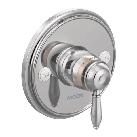
Range Master BELFAST CGR595WH User manual
Other Range Master Kitchen & Bath Fixture manuals

Range Master
Range Master Ellipse TEP1 User manual

Range Master
Range Master Aquadisc TAD5 User manual

Range Master
Range Master TAI1 User manual

Range Master
Range Master Belfast Bridge TBL1 User manual

Range Master
Range Master Cruciform TCF2BF User manual

Range Master
Range Master Paragon PAR4553AS User manual

Range Master
Range Master Aquatrend TRE1PO User manual
Popular Kitchen & Bath Fixture manuals by other brands

VIGO
VIGO Matte Stone VG04001 manual

Hans Grohe
Hans Grohe Zenio Metro 31811000 manual

Kohler
Kohler Contra 26448T-4 installation instructions

Hans Grohe
Hans Grohe Croma Select S 180 Showerpipe EcoSmart... Instructions for use and assembly instructions

Wickes
Wickes MONO SINK MIXER instruction manual

Grohe
Grohe ALLURE manual

Oliveri
Oliveri Munich MU7063C installation instructions

Graff
Graff PHASE E-6659-LM45W Instructions for assembly and use

Lefroy Brooks
Lefroy Brooks ZU X1-2030 Installation, operating, & maintenance instructions

Moen
Moen Show House TS514 Series installation guide

Spectrum Brands
Spectrum Brands Pfister F-WK1-1 manual

Moen
Moen Chateau 4904 instruction sheet

Kalia
Kalia KONTOUR BF1288 Installation instructions / warranty

Hans Grohe
Hans Grohe Axor Starck 10133 Series Installation instructions / warranty

DOCOL
DOCOL 016115 Series installation guide

Perrin & Rowe
Perrin & Rowe Mimas 4841 Installation & user guide

Rohl
Rohl Perrin & Rowe Georgian Bathroom U.3712LS Installation & user guide

baliv
baliv KI-5070 manual


