Range Rover Sport 2019 User manual

2019 Range Rover Sport PHEV
Towing and Road Service Guide
Quality and Education Services
AAA Automotive
December 26, 2018
For the latest updates from AAA, visit:
AAAcampus.aaa.biz

Index
Specications 3
Start/Stop Switch 4
Electronic Key/Mechanical Key 4
Door Locks 5
Rear Hatch Release 5
Hood Release 5
Fuel Door Release 6
Electronic Parking Brake 6
Car Carrier Loading 7
Towing Eyebolt Locations 8
Tires and Jacking 9
Jump-Starting Procedures 10
Charging Procedures 11
Important Notice:
This publication should not be used while driving. The procedures in this publication should only be
used by qualied and trained personnel.
ThisRoadServiceQuickReferenceGuidewasdevelopedtohighlightsomemodel-specicinformationand
common procedures for servicing or towing this vehicle. It is not all-inclusive. For complete information:
The applicable vehicle's owner’s manual and the AAA/CAA Towing and Service Manual should be used in
conjunction with this guide.
Theproceduresrecommendedanddescribedinthisguideareeectivemethodsofperforminglightservice
and towing operations. Some of these procedures require the use of auxiliary equipment specially designed
for the purpose. The auxiliary equipment should be used as recommended and whenever the trained
operator deems it appropriate. It is important to read the various WARNINGS, CAUTIONS and NOTES
in this manual in order to minimize the risk of personal injury to service personnel and or customers and to
avoid procedures which may damage the vehicle or render it unsafe. It is also important to understand that
these warnings, cautions and notes are not exhaustive. Neither AAA nor the auto and towing equipment
manufacturers could possibly know, evaluate and advise the reader of all conceivable methods of towing or
evaluate individual situations. Accordingly, anyone who uses a towing procedure must be thoroughly
convinced that neither personal safety nor vehicle safety will be jeopardized by the selected procedure.
AAA is not responsible for changes made by the manufacturers to the vehicles or their recommendations.
Important changes in procedures and updates will be furnished to all manual users at AAACampus.aaa.biz.
AAA
Attention: TTR
1000AAADrive,MS33
Heathrow,FL32746
2

3
AAA Towing and Road Service Guide for 2019 Range Rover Sport PHEV
SPECIFICATIONS:
Dimensions:
Length: 192.2 inches
Width: 87.4 inches
Specications
Curb Weight (pounds) 5,430
Drive Line Type All-Wheel Drive (AWD)
Length 192.2 inches
Width 87.4 inches
Wheelbase 115.1 inches
Height 71.6 inches
Fuel Type Gas (Octane 87 or higher /
Battery Electric)
Engines Available based on submodels
Range Rover Sport Available Engine
Plug-in Hybrid Electric Vehicle
(PHEV)
2.0L 247 HP Turbocharged 4-cylinder Gasoline

NOTE: The electronic key must be in the vehicle.
• Ignition On / Engine O: Withyourfootothe
brake pedal, press and hold the Start/Stop switch
until the warning lights on the instrument panel
illuminate.
• To start the engine: Press the Start/Stop switch
while depressing the brake pedal.
NOTE: It is not possible to start a PHEV if it is plugged
into a charging point. Make sure the vehicle is un-
plugged prior to attempting to use the Start/Stop switch.
4
START/STOP (IGNITION) BUTTON OPERATION:
Electrically Adjusted Manually Adjusted
When the electronic key is not detected:
1. Press the brake pedal.
2. Depending on the type of steering column present,
touch the back of the electronic key to the designat-
ed area of the steering column. When the electronic
key is detected, a buzzer sounds and the engine
switch will turn to IGNITION ON mode.
Remote Functions (Top-Bottom)
1. Locks the doors
2. Unlocks the doors
3.RearHatch(pressandhold)
4. Sounds the alarm
5.TurnsonHeadlightsfor30seconds
ELECTRONIC KEY/MECHANICAL KEY:
To access the mechanical key, press the release but-
ton shown by the thumb on the remote in the image
and slide the key out. The mechanical key can only be
inserted in one direction, as the key has grooves on one
side. If the key cannot be inserted in a lock cylinder,
turn it over and re-attempt to insert it. After using the
mechanical key, store it in the electronic key.

Using the Remote:
1. Press buttons to lock and unlock the door.
2. Press the button on the inner handle to lock and
unlock the door.
NOTE: The electronic key needs to be with the person
attempting to lock or unlock the door so the key can be
recognized.
5
REAR HATCH RELEASE:
Remote:
• Pressandholdbutton3inimageAtillthetailgate
begins to open.
External Button:
• With the electronic key within range (9 ft.), open the
tailgate by pressing button 1 in image B. Image
B
Image
A
DOOR LOCKS:
Using the Mechanical Key:
1. If the smart key and keyless entry fail to open the
vehicle, insert the key blade into the lock barrel
behind the driver's door handle. To access the lock
barrel, remove the cover using the mechanical key
in the slot provided by lifting the cover away from
the door (shown in Step 1 image). Use care to avoid
scratching painted surfaces.
2. Unlock the door by turning the key.
Opening the Hood:
1. This vehicle is equipped with a mechanical hood
release on the driver's side kick panel.
2. Slide the hood safety catch, located below the center
point of the hood to the passenger side.
3. Raise the hood.
HOOD RELEASE:
Step
1
Step
2

6
This vehicle is equipped with an electric parking brake.
The system uses a switch located at the base of the center
console near the gear selector. This applies and releases the
parking brake.
1. Pull the switch up to apply the parking brake. The park-
ing brake indicator light will turn on.
2. Push down on the switch to release the parking brake.
Theparkingbrakeindicatorlightwillturno.
If the vehicle can be started normally:
To select Neutral, secure the vehicle, power vehicle to
"ON," press the brake pedal, squeeze the trigger (shown in
lower image) and slide the gear selector to “N." With the
vehicle in neutral, press and hold start/stop button.
If the vehicle has power, but will not start:
Withyourfootothebrakepedal,pushtheStart/Stopbut-
tononce.(theenginewillbeo,andtheshiftpositioncan
be changed to Neutral.)
Shift Override:
This vehicle is equipped with a shift override procedure
that will place the transmission in Neutral. To access the
override, remove the engine cover by lifting it up. Locate
theoverrideneartheoilllcap.Lifttheleverup90de-
grees until it locks in the vertical position.
NOTE: Secure vehicle with wheel chocks prior to placing
the vehicle in Neutral.
SELECTING NEUTRAL:
ELECTRONIC PARKING BRAKE:
Selecting Park:
Press the "P" located on
top of the gear selector.
This vehicle is equipped with a push-lock fuel door. To
open the fuel door, push the left side of the door to release
the lock and pull the door open. After fueling, close the
door and push it in to lock the door.
NOTE: Prior to opening the fuel door: The manufacturer
has included a fuel button on the left-lower dash that locks
the fuel door and allows the vehicle to vent prior to being
opened.
FUEL DOOR RELEASE:

CAR CARRIER LOADING AND TRANSPORTING:
Special Precautions:
• Car carrier equipment is the preferred method of towing this vehicle.
• When loading or winching, DO NOT USE HOOKS OF ANY TYPE ON THE LOWER CONTROL
ARMS OR ANY OTHER STEERING OR SUSPENSION COMPONENT. Carefully follow the
loadingproceduresspeciedonthefollowingpages.
• USE ONLY WHEEL STRAP TIE-DOWNS to secure this vehicle when transporting. The use of
chains or hooks will damage under-vehicle components.
• To have steering capabilities, power to this vehicle is required and the vehicle needs to be in the
"ON" setting.
• In an emergency situation where the vehicle will not roll or must be moved for towing access,
wheel-jacking equipment, such as GoJaks or tire skates, are recommended.
• If the vehicle's electronics are operational, the air suspension must be set to "Access Height," before
securing. Failure to do so can result in damage to the vehicle.
• Utilize as much ramping as required to reduce the approach angle and retain adequate ground clear-
ance at the front and rear of the vehicle.
7
CAR CARRIER LOADING PROCEDURE:
Tie-down Method:
• Whenthevehicleisinitsloadedpositionontheatbedandthedeckofthecarcarrierisstillinthe
deployedposition,securethevehiclewithawheelchocktopreventitfromrollingandattachtherst
wheel strap over the tire closest to you. Continue securing the vehicle on all four corners.
• Once the bed is in its transport position and the vehicle is secured to the bed with four wheel strap tie-
downs, place the transmission into Park and ensure the parking brake is set to help secure the vehicle.
• Clearance around the wheel is limited and careful routing of straps is needed to avoid contacting brake
lines and wheel speed sensor wires, especially behind the front wheels. Careful routing of the straps is
also important to avoid contact with the painted surfaces of the vehicle.
• After securing, slacken the winch line slightly to prevent any downward pull on the towing eyebolt. This
will help to prevent damage if bumps are encountered during transport. Ensure the Start/Stop button is
OFF and the electronic key is removed from the vehicle.

8
CAR CARRIER LOADING PROCEDURE:
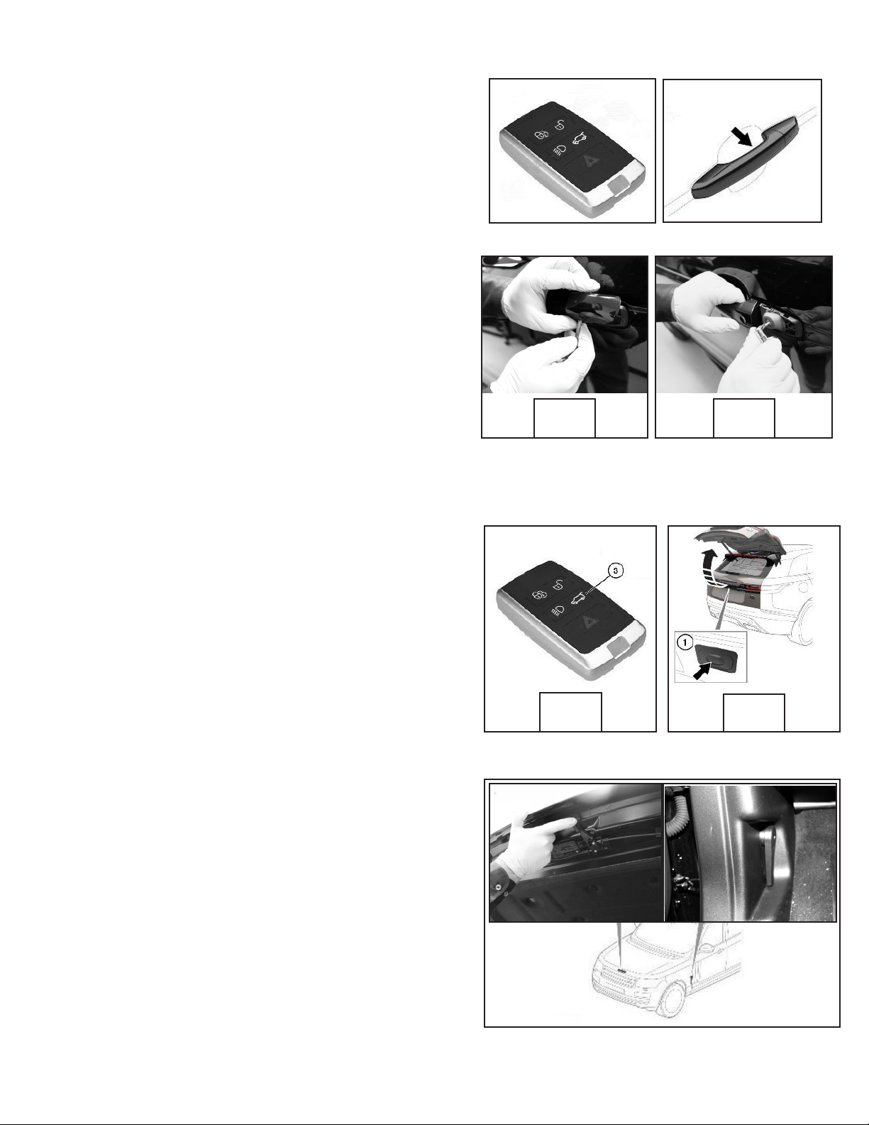
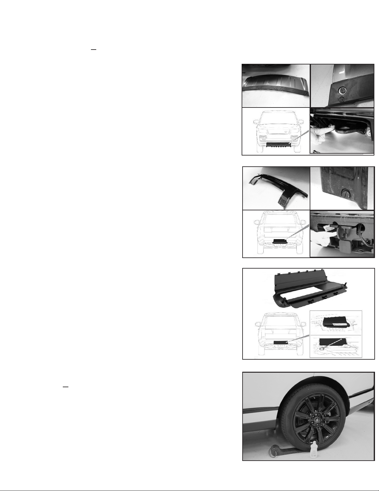
Rear Towing Eyebolt: (image 3)
Vehicles not equipped with a receiver hitch may come equipped with
a rear towing eyebolt. The eyebolt is stored in the rear compartment
withthetireinatorkit.
NOTE: The eyebolt is designed for a straight pull within a 20 degree
window. Only load the vehicle onto the carrier deck far enough to
safely transport the vehicle. Stop loading when the winch line begins
to pull downward. To prevent downward pull, keep the leading edge
of the vehicle at least 2 feet from the winch drum (this will vary
based on the towing equipment used).
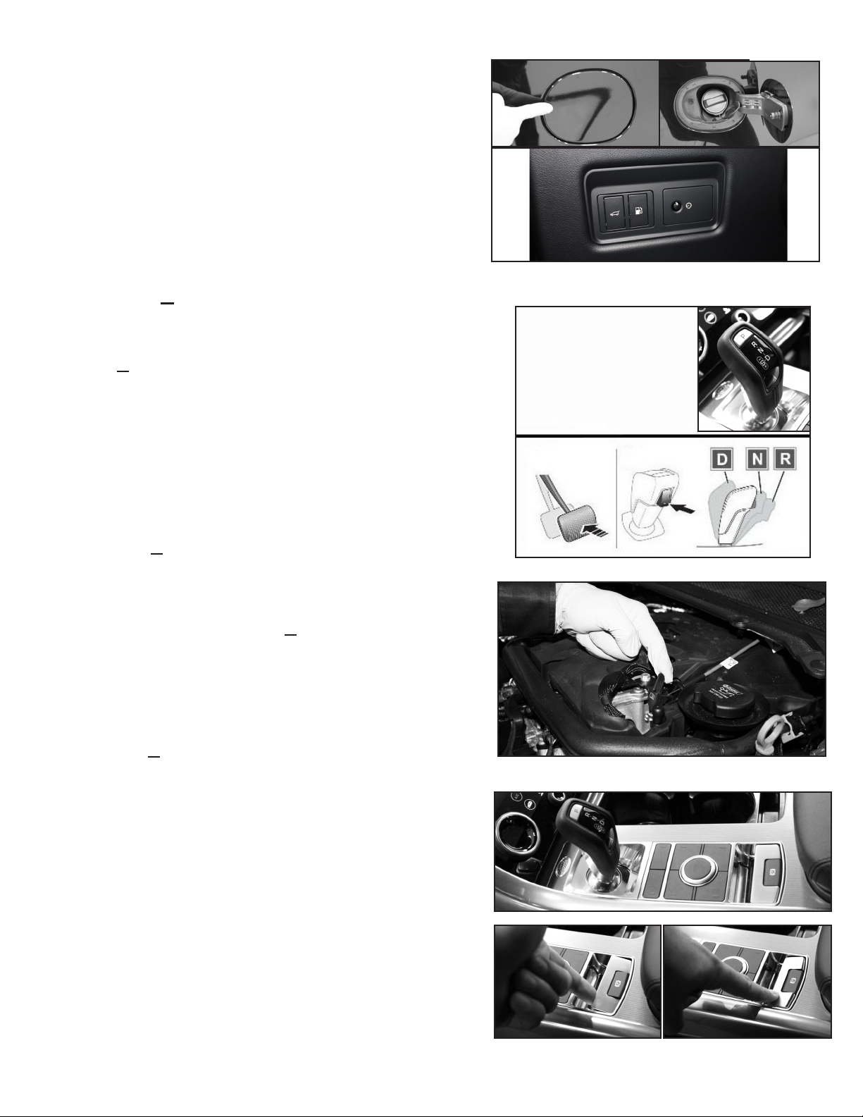
SKATES: (image 4)
In the event Neutral cannot be selected or a failure with the parking
brake mechanism causes the wheels not to roll, wheel dollies such as
“GoJaks” or tire skates can be used under the non-rolling wheels to
assist with loading the vehicle. Care must be taken when installing
tire skates or GoJaks due to the limited clearance around the wheels
and between the vehicle and the ground.
Car Carrier Loading Procedures:
• Before loading, secure the vehicle, ensure the
transmission is in Neutral and the parking brake is
released.
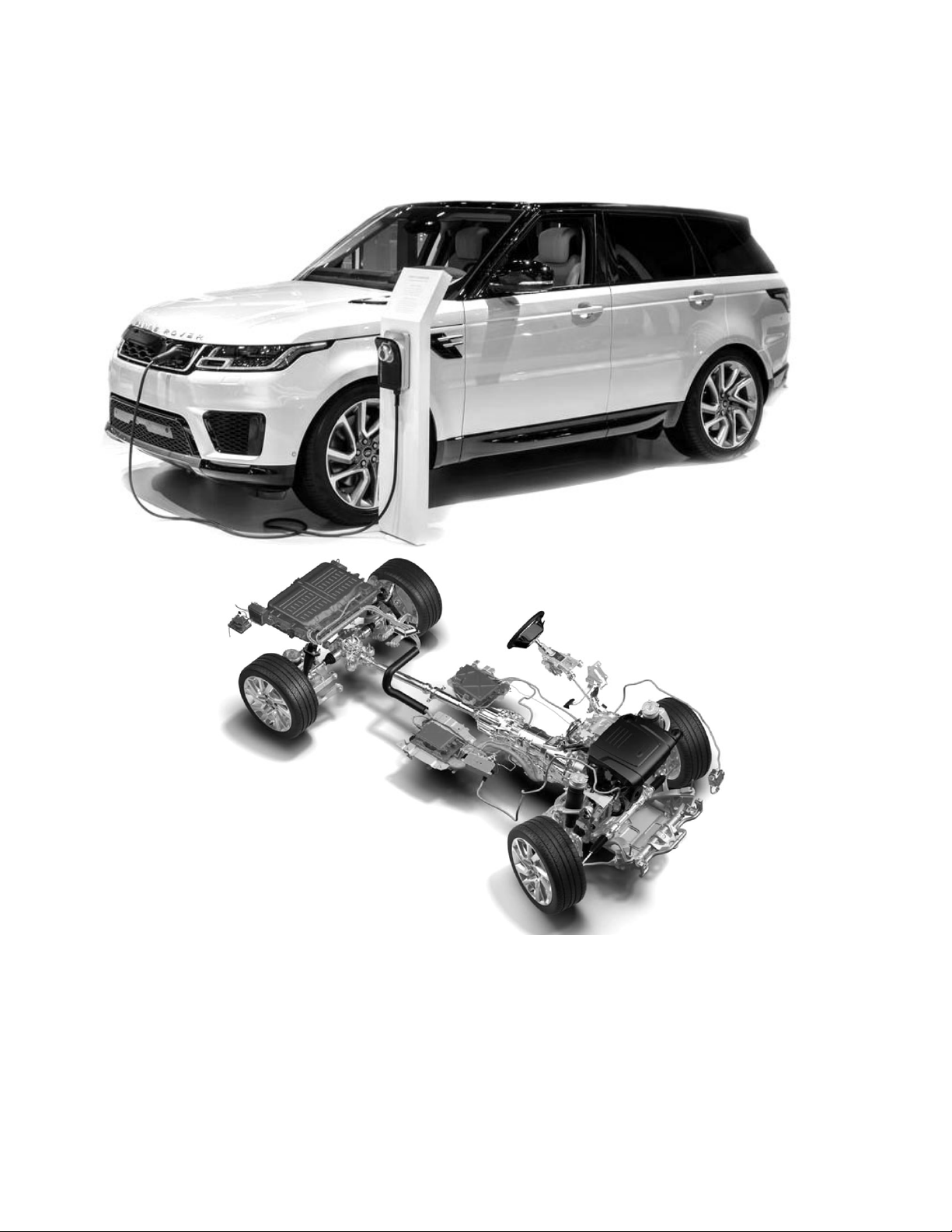
Front Attachment Location: (image 1)
This vehicle is equipped with a towing eye that should
be used for loading and unloading. It is located under a
plastic cover in the center of the lower-front bumper.
1. Unscrew the four fasteners counter-clockwise with a
non-marring tool to release the rear lower edge.
2. Starting at one end, pull the cover forward from the
rear lower edge to release the locating tabs and clips
on the top edge of the cover.
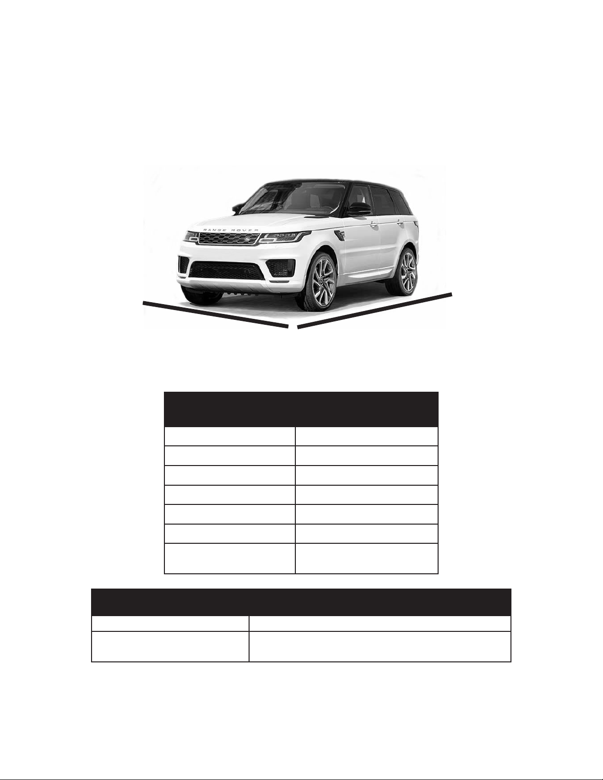
Rear Attachment Location: (image 2)
This vehicle is equipped with a towing eye behind a
removable plastic cover under the rear bumper.
1. Unscrew the two fasteners counter-clockwise with a
non-marring tool to release the lower edge.
2. Starting at one end, pull the cover forward from the
rear lower edge to release the locating tabs and clips
on the top edge of the cover.
1
2
3
4

9
Jacking Locations:
Place the jack in its proper location. Observe all
standard jacking precautions and ensure the vehicle
isonrm,levelgroundwiththewheelschocked.
As the jack comes in contact with the vehicle body,
ensure it is contacting the correct location on the
vehicle. Continue lifting the vehicle high enough
to execute the services needed.
Thisvehiclemaycomeequippedwithatireina-
tor kit from the factory. These items can be found
in the tool kit located inside the rear hatch.
Inator Kit:
1. Luggagecompartment'soorpanel.
2. Compressor
3. Sealant bottle
4. Locking wheel nut adaptor
Tire Pressure:
The manufacturer’s recommended
tire pressures can be found on the tire
placard located on the driver’s door
pillar and in the owner’s manual.
TIRES AND JACKING:
Spare Tire and Tool Locations:
This vehicle may be equipped with a spare tire
andtoolslocatedundertheoorpaneloftherear
compartment.
1. Loadspaceoorpanel
2. Jack and tools: Located under the spare wheel
3. Spare wheel's lift assist tool
4. Locking wheel nut adaptor
5. Jack handle
6. Wrench tool
7. Jack strap
NOTE: Priortousingtheinatorkit,makesureto
get permission from the owner.

10
JUMP-STARTING PROCEDURES:
The battery in this vehicle is an Absorbed Glass Matt (AGM )
locatedundertheinatorkitintheluggagecompartment.
Follow the jump-starting procedures listed below:
• Follow all normal jump-starting precautions as out-
lined in the AAA/CAA Towing & Service Manual
and the owner’s manual.
• Secure the vehicle.
• Ensure the Start/Stop button and all electrical ac-
cessories are turned OFF and the electronic key is
removed from the vehicle before connecting jumper
cables or a jumper box to the discharged vehicle.
• Connect the (+) positive lead to the vehicle's positive
boostterminalonthepassenger'sside(gure1).
• Connect the (-) negative jump lead to the vehicle's
negativeboostterminal(gure2).
• Starttheengineandallowittoidle(gure3).
• Allow the discharged vehicle to charge a few minutes
before disconnecting the jump leads.
• Disconnect in the reverse order.
NOTE: Manufacturerstatesthefollowingeectscanbe
expected if the battery gets disconnected or is severely dis-
charged:
• Alarm may trigger, depending on its state when the
battery is disconnected. If the alarm does sound, use
the smart key, in the normal way, to disarm the security
system.
• The windows may need recalibrating to operate correctly.
TIP: To help prevent these concerns, use a charged Keep
Alive Memory (KAM) unit to provide power to the vehicle
while the battery is disconnected. It is important to note that
thememorymayalreadybeaecteddependingonthebat-
tery's charge before installing the KAM unit.
1
2
3

11
For the latest updates from AAA, visit: AAAcampus.aaa.biz
CHARGING PROCEDURES:
The vehicle is equipped with a Plug-in Hybrid system that
allows the electric batteries to be recharged.
Thefollowingliststhespecicsofthissystem:
• Follow all precautions as outlined in the AAA/CAA
Towing & Service Manual and the owner’s manual
when working with any High-Voltage equipped
vehicles.
• The charging port is located behind the front grille
(gure1).Withthevehicleunlocked,pushthetop
right corner of the grille and pull it open to access
the charging port cap. Once open, move the cap
asidetogainaccesstothechargingport(gure2).
• Charging cable being used is required to meet the
ACchargingstandardSAEJ1772(gure3).
• Connecting Charging Cable Procedure:
- Unlock the vehicle
- Make sure Park is selected
-Makesurethevehicle'signitionisswitchedo
- Plug in the domestic connector to the electrici-
ty supply (Always connect the cable completely
stretchedouttotheelectricsupplyrst)
- Open the charging port and remove the cap
- Connect the charging cable to the charge port
- The LEDs on either side of the charge port will
ashwhitetoconrmthatvehiclecharginghas
been initialized
• Disconnecting the Charging Cable Procedure:
- Unlock Vehicle, verify the vehicle is in Park, and
theignitionisswitchedo
- Press the release button on the cable, if equipped,
and disconnect the charging cable from the vehicle
(Always disconnect from the vehicle rst)
- Place the cover on the charge port
- Unplug the charge cable from the electric source
• Charging Cable Emergency Release is located
underthehoodabovethechargeport(gure4).
NOTE: Manufacturer states this vehicle supports AC
charging only.
1
2
3
4
Table of contents