Raychem 920 Series Service manual
Installation and Operation Instructions
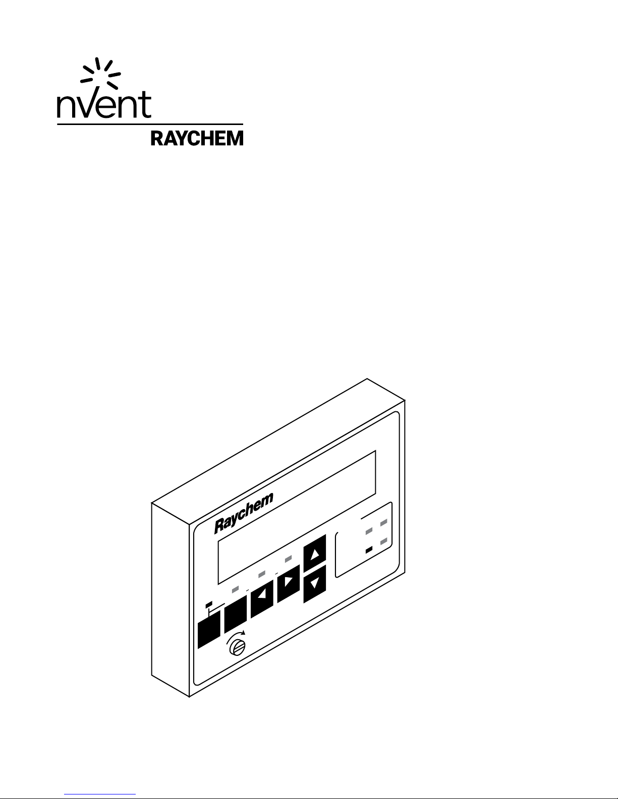
920 SERIES HEAT TRACE
CONTROLLER OPERATOR CONSOLE
Firmware Versions up to and including V3.2x
PROGRAMMABLE DUAL POINT
HEAT TRACING CONTROLLER
Tx
Rx
A
B
ALARM
LOCK
MONITOR CONFIG
STATUS
ALARM
OUTPUT
92
0
SERIES
A/BSHIFT
BACK ENTER

2 |nVent.com

nVent.com |3
CONTENTS
Installation and Maintenance instructions for Firmware Versions up to and including V3.2FX................ 4
Certication .................................................................................................................................. 4
Limited Warranty .......................................................................................................................... 4
Warranty Exclusion/Disclaimer ................................................................................................... 4
Exclusive Remedies...................................................................................................................... 4
Conducted and Radiated Emissions - FCC/DOC Statement of Compliance ............................ 4
Section 1 Overview................................................................................................................................... 5
1.1 Introduction................................................................................................................................. 5
1.2 Controllers Covered By This Manual ......................................................................................... 5
1.3 Product Overview........................................................................................................................ 5
1.3.1 Description ........................................................................................................................ 5
1.3.2 Features............................................................................................................................. 5
1.4 Ordering Information .................................................................................................................. 5
Section 2 Installation ............................................................................................................................... 6
2.1 Introduction................................................................................................................................. 6
2.2 Initial Inspection ......................................................................................................................... 6
2.3 Operator Safety Considerations................................................................................................. 6
2.4 Operating Environment............................................................................................................... 6
2.5 Installation Location................................................................................................................... 6
2.6 Installation and Removal Procedures ....................................................................................... 7
2.6.1 Operator Console Installation and Removal ................................................................... 7
Section 3 User Interface & Operation....................................................................................................... 8
3.1 Alpha-Numeric Display............................................................................................................... 8
3.2 Keypad......................................................................................................................................... 8
3.3 LED Indicators............................................................................................................................. 9
3.4 Operational Basics...................................................................................................................... 9
3.4.1 Operating Modes .............................................................................................................. 9
3.4.2 Menus................................................................................................................................ 9
3.4.3 Changing the Conguration ........................................................................................... 10
3.4.4 Changing a Non-Numeric Parameter ............................................................................ 10
3.4.5 Changing a Numeric Parameter..................................................................................... 10
3.4.6 Passcode Protection ...................................................................................................... 10
3.4.7 Switching Between Points A and B................................................................................ 11
3.4.8 Quick Notes on Operation .............................................................................................. 11
Section 4 Operating Modes.................................................................................................................... 12
4.1 Alarm Mode............................................................................................................................... 12
4.1.1 Resetting One Alarm....................................................................................................... 12
4.1.2 Resetting All Alarms ....................................................................................................... 12
4.1.3 Monitor Mode Tracking .................................................................................................. 12
4.1.4 Alarm Messages............................................................................................................. 12
4.2 Monitor Mode ........................................................................................................................... 13
4.2.1 Main Menu....................................................................................................................... 13
4.2.2 “MAINTENANCE DATA...” Sub-Menu ............................................................................. 13
4.3 CONFIGURE MODE ................................................................................................................... 14
4.3.1 Main Menu....................................................................................................................... 14
4.3.2 “TS ALARM CONFIG...” Sub-Menu ................................................................................. 14
4.3.3 “OTHER ALARMS CONFIG...” Sub-Menu........................................................................ 15
4.3.4 “POINT SETUP...” Sub-Menu ........................................................................................... 16
4.3.5 “COMMON SETUP...” Sub-Menu..................................................................................... 17
4.3.5.1 “COPY CONFIG...” Sub-Menu ............................................................................ 17
4.3.6 “COMMUNICATIONS SETUP...” Sub-Menu..................................................................... 18
Section 5 Maintenance........................................................................................................................... 19
5.1 OPERATOR MAINTENANCE..................................................................................................... 19
5.2 REPLACEABLE PARTS.............................................................................................................. 19
Section 6 Specications......................................................................................................................... 19

4 |nVent.com
INSTALLATION AND MAINTENANCE INSTRUCTIONS FOR FIRMWARE VERSIONS UP TO AND INCLUDING V3.2FX
This manual provides information pertaining to the installation, operation, testing, adjustment,
and maintenance of the nVent RAYCHEM Model 920 Series Heat Trace Control and Monitoring
products.
Additional copies of the operating manual may be ordered separately through your nVent
representative or online at nVent.com using the document number H56903.
Notice: The information contained in this document is subject to change without notice.
Certification
nVent certifies that this product met its published specifications at the time of shipment from
the Factory.
Limited Warranty
This nVent product is warranted against defects in material and workmanship for a period of
18 months from the date of installation or 24 months from the date of purchase, whichever
occurs first. During the warranty period, nVent will, at its option, either repair or replace
products that prove to be defective.
For warranty service or repair, this product must be returned to a service facility designated by
nVent. The Buyer shall prepay shipping charges to nVent and nVent shall pay shipping charges
to return the product to the Buyer. However, the Buyer shall pay all shipping charges, duties,
and taxes for products returned to nVent from another country.
nVent warrants that the software and firmware designated by nVent for use with the RAYCHEM
920 Controller will execute its programming instructions properly. nVent does not warrant that
the operation of the hardware, or software, or firmware will be uninterrupted or error-free.
Warranty Exclusion/Disclaimer
The foregoing warranty shall not apply to defects resulting from improper or inadequate
maintenance by the Buyer, Buyer-supplied software or interfacing, unauthorized modification or
misuse, operation outside of the specifications for the product, or improper installation.
No other warranty is expressed or implied. nVent disclaims the implied warranties of
merchantability and fitness for a particular purpose.
Exclusive Remedies
The remedies provided herein are the buyer’s sole and exclusive remedies. nVent shall not be
liable for any direct, indirect, special, incidental, or consequential damages, whether based on
contract, tort, or any other legal theory.
Conducted and Radiated Emissions - FCC/DOC Statement of Compliance
This equipment has been tested and found to comply with the limits for a Class A digital
device, pursuant to Part 15 of the FCC rules. These limits are designed to provide reasonable
protection against harmful interference when the equipment is operated in a commercial
environment. This equipment generates, uses, and can radiate radio frequency energy and,
if not installed and used in accordance with the instruction manual, may cause harmful
interference to radio communications. Operation of this equipment in a residential area is
likely to cause harmful interference, in which case the user will be required to correct the
interference at his own expense.
This equipment does not exceed Class A limits for radio emissions as set out in Schedule V to
VIII of the Radio Interference Regulations of Communication Canada.
Cet appareil respecte les limites de bruits radioelectriques applicables aux appareils
numeriques de Classe A prescrites dans la norme sur le materiel brouilleur: “Appareils
Numeriques”,
NMB-003 edictee par le Ministre des Communications.

nVent.com |5
SECTION 1 OVERVIEW
1.1 INTRODUCTION
This manual provides information pertaining to the installation and operation of the
RAYCHEM 920 Series Heat Trace Controller Operator Console. For information relating to
theprogramming, installation maintenance and troubleshooting of other 920 Series products,
including the Dual Point Control Module, Controller Assemblies, etc., please refer to the
920Series Controller Manual.
Additional copies of this manual may be ordered separately through your nearest sales office
using the order number listed on the front cover.
1.2 CONTROLLERS COVERED BY THIS MANUAL
This document covers the 920 Series Heat Trace Controller Operator Console. The information
coincides with the specific releases of firmware for the 920 product which are listed on the
front page. As nVent releases new firmware to modify or enhance the product significantly,
new documentation will accompany these releases. To ensure that you are using the correct
documentation for your particular version of controller, please check the firmware version
number of the 920 against the version number listed on the front of this manual. This may be
displayed using the 920 Series Operator Console or a communicating device. As subsequent
changes are made, updates will be included in manuals shipped after the firmware is released.
If issued, supplements will make specific reference to any operational or functional changes.
1.3 PRODUCT OVERVIEW
1.3.1 Description
The 920 Series Operator Console provides a simple, easy to use interface to the Dual Point
Controller, alleviating the need for a communicating device to configure the Controller. The
Console allows you to look at or reset alarms, test or monitor the heat tracing, and examine or
alter the configuration.
The Console may be left installed permanently or may be installed temporarily for display/
setup during maintenance and troubleshooting. Access is available for all monitored
parameters, programmed values, and alarm information. Enhanced security is provided by
password protection.
The unique design of the Operator Console allows it to be installed or removed under power
even in hazardous areas.
1.3.2 Features
Keypad and Alpha-numeric Display
A six character alpha-numeric LED display provides the operator with large easy to read
messages and prompts, eliminating complex and cryptic programming. Six individual keys are
provided to quickly access alarming and operational information.
–40 to 140°F (–40 to 60°C) Operation
Extended temperature operation permits installation in all but the harshest environments.
CSA C/US & FM Approved
The 920 Series Operator Console is approved for Class I, Division II, Groups A,B,C,D and Zone 2
hazardous locations making it ideal for direct use in the field.
1.4 ORDERING INFORMATION
The 920 Series Operator Console is ordered as a separate item from the Controller Assembly
or other components. It may be ordered as Model #920CON. Please refer to the latest
RAYCHEM 920 Series Ordering Guide for additional information.
IMPORTANT WARNINGS AND NOTES
The following icons are used extensively throughout this manual to alert you to important warnings
that affect safety and to important notes that affect the proper operation of the unit.
Be sure to read and follow them carefully.
Table of contents


