redpod FIRST 6 kW User manual

FIRST 6 kW
Pellet Stove
Instruction Manual
Read the instructions carefully before installing, operating and maintaining the
equipment. The operating instructions are an integral part of the product.
Mod.942-B

Index
1. Package contents ...................................................................................................... 4
1.1. Unpacking the stove ............................................................................................ 4
2. Safety warnings........................................................................................................ 4
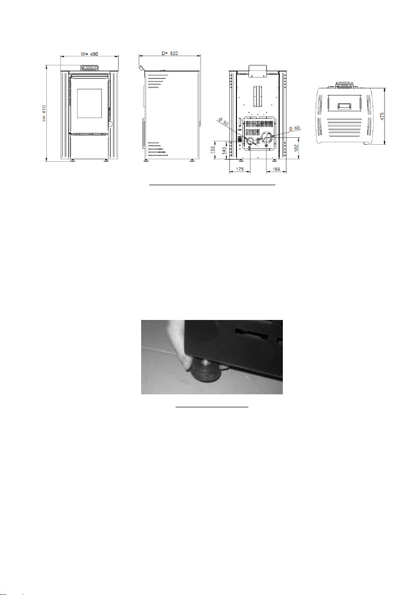
3. Technical specifications* ............................................................................................ 6
4. Installation of the pellet stove .................................................................................... 7
4.1. Installation requirements ..................................................................................... 8
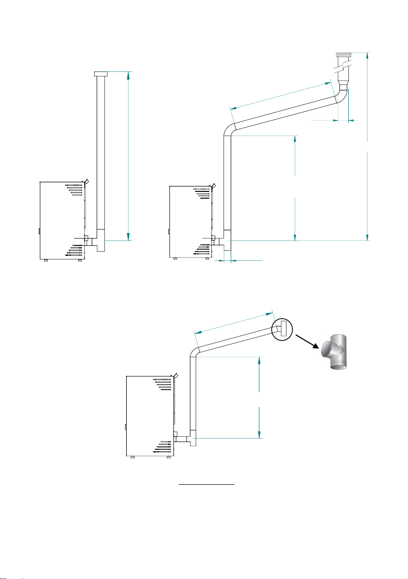
4.2. Installation of ducts and smoke exhaust systems .................................................... 8
4.3. Installation without chimney ................................................................................. 9
4.4. Installation with chimney ................................................................................... 12
5. Fuel ...................................................................................................................... 13
6. Use of pellet stove .................................................................................................. 14
7. Remote Control ...................................................................................................... 15
7.1. Infrared Remote Control..................................................................................... 15
7.2. Control and Display Panel................................................................................... 16
7.3. Display Information Summary............................................................................. 17
7.3.1. Selecting the Manual or Automatic Mode ................................................... 17
7.3.2. ECO Mode ............................................................................................. 18
7.3.3. Pellet Recipe.......................................................................................... 19
7.3.4. Pellet Loading ........................................................................................ 19
7.3.5. Cleaning ............................................................................................... 20
7.3.6. Thermostat ........................................................................................... 20
7.3.7. Combustion Air Offset............................................................................. 20
7.3.8. Mass Air Flow Sensor (not applicable to First units) .................................... 21
7.3.9. Pellet Level Sensor (not applicable to First Model units) .............................. 21
7.3.10. Date/Time............................................................................................. 21
7.3.11. Timer ................................................................................................... 23
7.3.12. Language .............................................................................................. 25
7.3.13. Infrared Remote Control ......................................................................... 25
7.3.14. Technical Menu ...................................................................................... 25
7.3.15. User Info .............................................................................................. 26
8. Alarm / Failure / Recommendation List .............................................................. 28
9. Columbus Electronics .............................................................................................. 30
9.1. Remote Control ................................................................................................. 30
9.2. Client Menu ...................................................................................................... 33
9.3. Submenu ......................................................................................................... 38
10. List alarms / faults / recommendations –Columbus Electronics .................................... 43
11. Start-up................................................................................................................. 45

11.1. Stop ................................................................................................................ 46
11.2. Turning Off the unit ........................................................................................... 46
12. Instruction for Installing the Display.......................................................................... 46
13. Refill the pellet tank ................................................................................................ 48
14. Maintenance ................................................................................................... 49
14.1. Daily maintenance............................................................................................. 49
14.1.1. Cleaning the inside of the stove ............................................................... 49
14.1.2. Cleaning the fume passage First 6kW ....................................................... 50
14.1.3. Cleaning the fume circuit First 6 kW ......................................................... 51
15. Installing and operating with the remote control - “programmable thermostat” (optional) 54
15.1. Installation instructions for the external control unit .............................................. 55
16. Maintenance Plan and Log ................................................................................ 58
17. Maintenance Guide Label ................................................................................. 62
18. Electrical Diagram of the Free-Standing Fire Unit ........................................................ 63
19. Life Cycle of a Free-Standing Fire Unit ....................................................................... 64
20. Warranty Conditions ................................................................................................ 64
20.1. Model-specific conditions .................................................................................... 64
20.2. Warranty General Conditions .............................................................................. 64
21. Annexes ................................................................................................................ 72
21.1. Timer weekly programming (not applicable to Columbus Electronics) ....................... 72
21.2. Timer daily programming (not applicable to Columbus Electronics) .......................... 73
21.3. Flow chart ........................................................................................................ 74
22. Declaration of performance ...................................................................................... 77

4
1. Package contents
The packaging of the equipment has the following content:
- Pellet Stove First 6kW;
- Access brochure to the online instruction manual;
- Power cable;
- Infrared remote control.
1.1. Unpacking the stove
In order to unpack the equipment, you must first remove the retractable bag around
the cardboard box. Then remove the box by lifting it up and remove the bag around
the stove and the styrofoam plates. Finally, the four pieces holding the equipment to
the wooden pallet should be loosened (Figure 1).
Figure 1 - Unpacking
2. Safety warnings
•Make sure you fully read and understand the instructions contained in this manual
before using the Free-Standing Pellet Fire as a biomass heating unit.
•The Free-Standing Pellet Fire is not intended for use by children or people physically
and/or mentally challenged, or that are inexperienced or unfamiliar with using the unit,
except when under supervision or after receiving proper training.
•Do not touch the Free-Standing Fire when barefoot or if any part of your body is
wet or humid;
•Do not tamper with the safety devices or adjustment features without the
permission of the REDPOD manufacturer;
•Do not cover or reduce the size of the vents at the installation area;

5
•The installation of the Free-Standing Pellet Fire has clearance requirements for
proper combustion, so the air tight isolation of the room where the equipment is to be
installed or the existence of air extraction sources in the room may prevent the unit
from working properly;
•The existence of vents is a requirement for proper combustion;
•Please keep the packing materials away from children;
•During normal operation, DO NOT open the door of the unit;
•Some parts may overheat during normal operation, so the direct contact with hot
parts, such as the door handle and glass, should be avoided;
•Check for the existence of any obstructions to the fume duct before turning on the
unit after a long idle period;
•This Free-Standing Pellet Fire unit is intended for residential use in areas with the
adequate protections in place. Safety systems may be triggered, which will be turning
off the unit. If this occurs, contact the technical assistance. Under no circumstances
should you attempt to tamper with the safety systems;
•The Free-Standing Pellet Fire is a biomass heating unit equipped with an electric
fume extractor. The occurrence of a power failure during its use may prevent the fume
to be extracted, consequently causing the room to be filled with smoke. For this
reason, a natural fume extraction system, like a chimney, is recommended;
•NEVER turn off an operating Free-Standing Pellet Fire unit by disconnecting the
electric plug. The fume extractor on the Free-Standing Pellet Fire unit is a powered
feature, so disconnecting the power plug will prevent the extraction of combustion
fumes;
•The unit must be disconnected from the mains power before any maintenance
procedures can be performed. Please allow the unit to cool down completely before any
maintenance operation (if operating before);
•Never touch the interior of the unit without disconnecting it from the power mains;

6
3. Technical specifications*
Characteristics
First 6 kW
Units
Weight
65
kg
Height
810
mm
Width
490
mm
Depth
520
mm
Diameter of the fume discharge pipe
80
mm
Tank capacity
11
kg
Maximum heating volume
139
m³
Maximum overall thermal input
6,1
kW
Minimum thermal input
3,2
kW
Minimum fuel consumption
0,68
kg / h
Maximum fuel consumption
1,36
kg / h
Rated electrical power
100
W
Electrical power at start (<10 min.)
378
W
Rated voltage
230
V
Nominal frequency
50
Hz
Thermal efficiency at rated thermal input
92
%
Thermal efficiency at reduced thermal input
95
%
Maximum gas temperature
123
°C
Temperature min. of gases
66
°C
CO emissions at nominal thermal power
0,01
%
CO emissions at reduced thermal power
0,04
%
Mass flow of combustion gases
5
g/s
Depression in the chimney
12
Pa
Table 1 - Technical specifications
* Tests performed using wood pellets with a calorific value of 4,9 kWh/kg.
The above data were obtained in the product homologation tests in independent and accredited laboratories, in
order to carry out tests on pellet equipment.

7
Front Side Back Top
Figure 2 - First 6kW pellet stove dimensions
4. Installation of the pellet stove
Before starting the installation, perform the following actions:
•Upon delivery, please check the product for completeness and to determine the
existence of any signs of damage. Any damages or defects should be accounted for
before the unit is installed.
•This unit is equipped with four feet at the base, adjustable in height, allowing for
the easy regulation when installing the unit on a non-levelled surface.
Figure 3 - Adjustable feet
•Remove the instruction manual from the package and hand it over to the client;
•Connect an 80 mm-wide duct between the combustion gas output and the outgoing
fume extraction duct of the building (e.g. chimney). See location diagrams, sections
4.1 to 4.3.
•The tube used for combustion air inlet from the outside, if installed, must be
straight (no bends) and have a maximum length of 60cm horizontally;
•Connect the 230VAC power cable to a grounded socket.
•The hot air outlet side of the unit must be installed facing the area to be heated.

8
4.1. Installation requirements
The minimum distances from the pellet stove to particularly flammable surfaces are
shown in Figure 4.
At the top of the stove, it is necessary to keep a minimum distance of 100 cm from the
ceiling of the room, especially if they contain flammable material in their composition.
The base on which the stove rests must not be made of combustible material (e.g.,
carpet), so there must always be adequate protection.
DRAWN
CHECKED
ENG APPR
MGR APPR
UNLESS OTHERWISE SPECIFIED
DIMENSIONS ARE IN MILLIMETERS
ANGLES ±X.X°
2 PL ±X.XX 3 PL ±X.XXX
NAME
João Amaral
DATE
08/04/15 Solid Edge
TITLE
SIZE
A2 DWG NO REV
FILE NAME: Anexo 1- Figura 5- FISRT-PT_ES_FR_EN_IT.dft
SCALE: WEIGHT: SHEET 1 OF 1
REVISION HISTORY
REVDESCRIPTION DATE APPROVED
30 cm Min. 100 cm
Min. 50 cm
50 cm50cm
150cm
a) b)
Figure 4 - Minimum distances from all surfaces: (a) top view of the installation of the equipment; (b) side view of the
installation of the equipment
NOTE!
Keep combustible and flammable materials at a safe distance.
4.2. Installation of ducts and smoke exhaust systems
•The construction of the gas exhaust pipe must be suitable for this purpose in
accordance with the local requirements and the applicable regulations.
•Important! An inspection T- with a hermetic cap should be inserted at the exit
of the stove tailpipe to allow regular inspection or discharge of heavy dust and
condensate.
•As shown in Figure 4, the exhaust duct shall be carried out in such a way that
cleaning and maintenance is ensured by inserting the inspection points.

9
•In operating conditions at rated power, it must be ensured that the draught of the
combustion gases must cause a depression of 12 Pa, measured 1 meter above the
smoke outlet.
•The stove can't share the chimney with other equipment.
•The pipes outside the place of use must be double insulated in stainless steel, with
an internal diameter of 80 mm.
•The smoke exhaust pipe can generate condensation, in which case it is advisable to
establish suitable condensate collection systems.
4.3. Installation without chimney
The installation of the pellet stove when there is no chimney should occur, as in figure
5, bringing the smoke exhaust pipe (with minimum internal diameter of 80 mm)
directly out and above the roof.
Insulated double-walled stainless-steel pipes should be used properly anchored to
prevent condensation phenomena.
Provide a T at the base of the pipework for periodic inspections and annual
maintenance, as exemplified in figure 5.
Figure 5 - Side view of the installation without chimney, with example of the inspection point

10
Figure 6 shows the basic requirements for the installation of the stove's chimney.
DRAWN
CHECKED
ENG APPR
MGR APPR
UNLESS OTHERWISE SPECIFIED
DIMENSIONS ARE IN MILLIMETERS
ANGLES ±X.X°
2 PL ±X.XX 3 PL ±X.XXX
NAME
João Amaral
DATE
08/04/15 Solid Edge
TITLE
SIZE
A2 DWG NO REV
FILE NAME: Figura 7- FIRST- a) PT_ES.dft
SCALE: WEIGHT: SHEET 1 OF 1
REVISION HISTORY
REVDESCRIPTION DATE APPROVED
Mín. 2 m
DRAWN
CHECKED
ENG APPR
MGR APPR
UNLESS OTHERWISE SPECIFIED
DIMENSIONS ARE IN MILLIMETERS
ANGLES ±X.X°
2 PL ±X.XX 3 PL ±X.XXX
NAME
João Amaral
DATE
08/04/15 Solid Edge
TITLE
SIZE
A2 DWG NO REV
FILE NAME: Figura 7- FIRST- b) PT_ES.dft
SCALE: WEIGHT: SHEET 1 OF 1
REVISION HISTORY
REVDESCRIPTION DATE APPROVED
Mín. 4 m
Mín. 1 m
Máx. 3 m
Máx.2m
Incl. > 3- 5%
O10 cm
O8 cm
a) b)
DRAWN
CHECKED
ENG APPR
MGR APPR
UNLESS OTHERWISE SPECIFIED
DIMENSIONS ARE IN MILLIMETERS
ANGLES ±X.X°
2 PL ±X.XX 3 PL ±X.XXX
NAME
João Amaral
DATE
08/04/15 Solid Edge
TITLE
SIZE
A2 DWG NO REV
FILE NAME: Figura 7- FIRST- c) PT_ES.dft
SCALE: WEIGHT: SHEET 1 OF 1
REVISION HISTORY
REVDESCRIPTION DATE APPROVED
Mín. 2 m
Max.2m
Incl. > 5%
c)
Figure 6 –Examples

11
Non-compliance with these requirements jeopardises the correct functioning of
the stove and the consequent loss of the warranty. Follow the instructions in the
diagrams.
The stoves operate with the combustion chamber in a depressive state, so it is
absolutely necessary to have a smoke evacuation duct that extracts the combustion
gases properly.
Smoke duct material: The pipes to be installed shall be rigid, of stainless steel with a
minimum thickness of 0,5 mm, with joints for the connection between the different
sections and accessories.
Insulation: Smoke ducts should be double-walled with insulation to ensure that the
fumes do not cool during outdoor travel, which would cause inadequate draught and
condensation that could damage the appliance.
Inspection “T”: Always use a "T" at the exit of the stove.
Windproof terminal: A windproof terminal should always be installed to prevent the
return of fumes.
Chimney depression: The figures illustrate three standard diagrams with the
appropriate lengths and diameters. Any other type of installation must ensure that a
depression of 12 Pa (0,12 mbar) is generated, measured at maximum power and in a
hot state.
Ventilation: For the stove to function properly, an air inlet with a minimum cross-
section of 100 cm2must be provided in the room where the appliance is installed,
preferably near the back of the stove. The stove has a round tube (Ø50mm) that can
be connected to the outside of the room. It is recommended that this connection is no
longer than 60 cm in length and without any kind of disturbance (e.g. bends).
If the residence has an air exhaust system installed (e.g. kitchen extractor
fan), a top ventilation section must be installed, suitable to accommodate the
different air exhaust systems that exist in the house.

12
The installation of the unit on locations near kitchen exhaust fans or fume
extractors may prevent the unit from operating properly. It is recommended
that the unit is disconnected when these extractors are working.
4.4. Installation with chimney
As shown in figure 7, the installation of the pellet stove brings the exhaust pipe (with
Ø80 mm) directly to the chimney. If the chimney is too large, it is recommended to
intubate the smoke outlet with a tube with a minimum internal diameter of 80 mm.
Provide a "T" at the bottom of the pipe for periodic inspections and annual
maintenance, as shown in figure 7.
Figure 7 - Side view of the installation with chimney, with example of the inspection point
When the weather conditions are so adverse that they cause a serious disturbance in
the draught of fumes from the stove (in particular very strong winds), it is advisable
not to use the stove.
If the appliance is not to be used for an extended period of time, the user must ensure
that there is no blockage in the chimney tubes before switching on.

13
5. Fuel
The only fuel that should be used for the operation of the stove is. No other fuel may
be used.
Use only pellets certified to EN 14961-2 grade A1 with a diameter of 6 mm and a
length of between 10 and 30 mm.
The maximum permissible humidity for pellets is 8% of their weight. To ensure good
combustion, the pellets must maintain these characteristics, so it is recommended to
keep them in a dry environment.
The use of different pellets reduces the efficiency of the pellet stove and leads to
deficient combustion processes.
As a recommendation always opt for certified pellets not forgetting that
before buying large quantities you should always test a sample.
The physico-chemical properties of pellets (in particular size, friction, density and
chemical composition) may vary within certain tolerances and according to the
manufacturer. This can cause changes in the feeding process and consequently
different dosages (with more or less pellets).
In this way it may be necessary to adjust the quantity of pellets according to their
quality even if these are certified.
The stove allows the pellet dose to be adjusted to ± 25% during the start-up
phase and at the power levels (see point 7.3.3 of the manual).
The appliance may NOT be used as an incinerator.

14
6. Use of pellet stove
Recommendations
The following points must be checked before starting up the appliance:
- Make sure that the stove is correctly connected to the power supply via the 230VAC
power cable.
Figure 8 - Power connection plug
- Check whether the pellet tank is full. Inside the pellet tank there is a safety grid to
prevent the user from accessing the worm screw.
The combustion chamber of the stove and the door are built of iron sheet
painted with high temperature paint, releasing fumes in the first burns due to
the cure of the paint. Avoid touching the equipment during the first firing so
as not to leave permanent marks on the paint because it goes through a more
plastic phase during its curing process. The curing of the paint occurs at
approximately 300ºC during 30 minutes.
It should be checked that there is sufficient air circulation in the room where the
installation is carried out, otherwise the equipment will not work properly. For this
reason, it should be noted that there is other heating equipment that consumes air for
its operation (e.g., gas equipment, braziers, hoods, etc.), and that the operation of
these equipment is not recommended at the same time.
Pellet stoves are equipped with a probe to measure the ambient temperature. This
probe is attached to the grid at the back (Figure 9). For a better reading of the ambient
temperature, avoid contact of the probe end with the stove's body. If desired, you can
also attach it to the wall next to the machine.

15
Figure 9 - Ambient probe
7. Remote Control
7.1. Infrared Remote Control
Figure 10 - Infrared remote control
The infrared remote control allows the user to turn the unit on and off, control the fan
airflow and increase or decrease the unit's power level.
Note: the remote control must be activated on the display, see section 7.3.13. of this
manual.

16
7.2. Control and Display Panel
Figure 11 - Remote control buttons
Notes:
d) Power LED (GREEN): flashes when the machine is connected to the power mains or
during activation. Stays on when the unit is working in power mode (manual or
automatic mode).
e) Alarm LED (RED), automatically turns on when an alarm is triggered on the unit.
f) ECO mode is shown on the screen when enabled. Example of ECO mode enabled:
g) When the unit completes 2100 operation hours, a message appears on the display
requiring a maintenance operation to be performed before the counter can be reset
(accessible through the Technical Menu). Deleting the message does not impact the
normal operation of the equipment, as this is merely a warning. Example:
e) Alarm LED
f)
g)
h)
i)
a) Button no. 1 to turn the
unit ON/OFF, reset any errors,
confirm menu changes, and
toggle between the manual
and automatic modes.
b) Button no. 2 (selection
button): for email access
(press during 10 sec) used to
scroll menus to the left,
reduce the pellets recipe,
reduce the set-point
temperature and reduce the
power level.
c) Button no. 3 (selection
button): for email access
(press during 10 sec) used to
scroll menus to the right,
reduce the pellets recipe,
reduce the set-point
temperature and reduce the
power level.
d) Power LED
●

17
h) When the Timer is enabled, this information appears on the display. Example:
h) When the thermostat is enabled, this information appears on the display. Example:
7.3. Display Information Summary
7.3.1. Selecting the Manual or Automatic Mode
Display indicating the unit is “Off”.
Select operating mode: To select the operation mode, press the “ON/OFF” button to
select “Manu” for manual mode or “Auto” for automatic mode.
Auto mode: In this mode, the unit is turned on at maximum power until reaching a
temperature 1ºC above the selected temperature (set point temperature). After
reaching the selected temperature, the unit switches to the minimum operating power.
●
●
●

18
The set point temperature may vary between 5 to 40ºC.
To change the temperature set point, press the selection buttons (Button no. 2 to
decrease the temperature, Button no. 3 to increase the temperature).
Manu mode: In this mode, the unit will run at the power selected using the selection
buttons, which may vary between 1 (minimum operating power) and 5 (maximum
operating power).
To change the temperature level, press the selection buttons (Button no. 2 to decrease,
Button no. 3 to increase).
7.3.2. ECO Mode
If the unit is equipped with a thermostat that operates exclusively based on the
temperature, the "eco mode" can be enabled to reduce the fuel consumption. In this
mode, the unit operates at a set point temperature. The unit always runs at maximum
operating power until it reaches a temperature of 1ºC above the set point temperature.
when reaching this temperature, the unit starts operating at minimum operating power
for a present time period. After this time has elapsed, the unit turns off. It remains off
°

19
for another present period of time. When the measured room temperature drops to a
present value, the unit turns on again at the maximum operating power.
This mode is only available in automatic mode.
To enable the eco mode, press and hold Button no. 2 for 10 seconds to access the
Menu. Use this button to scroll the menu until the “eco” option is displayed. Then,
press On/Off to enable or disable as desired, using the selection buttons. Press On/Off
to confirm.
7.3.3. Pellet Recipe
This feature allows you to increase or decrease by 25% the amount of pellets. Press
and hold Button no. 2 for 10 seconds to access the Menu. Use this button to scroll the
menu until the “rpel” option is displayed. Then press ON/OFF access the parameter you
wish to change. Use the selection buttons (from -10 to +10) to increase or decrease the
number. Each unit must be multiplied by 2.5% to obtain the correct percentage. Press
“ON/OFF” to confirm.
7.3.4. Pellet Loading
This feature allows you to enable the worm drive to fill the channel when it is empty
to keep the unit running. To enable the pellet loading with the unit in OFF mode, press
and hold Button no. 2 for 10 seconds to access the Menu. Use this button to scroll the
menu until the “cape” option is displayed. Then press On/Off to access the parameter
you wish to change. Use the selection buttons to enable or disable the pellet loading.
Press ON/OFF to confirm.

20
7.3.5. Cleaning
This feature allows you to clean the burning basket manually. To enable cleaning with
the unit in OFF mode, press and hold Button no. 2 for 10 seconds to access the Menu.
Use this button to scroll the menu until the “limp” option is displayed. Then press
On/Off to access the parameter you wish to change. Use the selection buttons to
enable or disable. Press On/Off to confirm.
7.3.6. Thermostat
This function allows you to activate or deactivate the thermostat. To enable the
thermostat, press and hold Button no. 2 for 10 seconds to access the Menu. Use this
button to scroll the menu until the “tErA” option is displayed. Then press On/Off to
access the parameter you wish to change. Use the selection buttons to enable or
disable. Press On/Off to confirm.
7.3.7. Combustion Air Offset
Allows the user to set a range between -10% or +10% for the combustion air during
the activation period and operation. Press and hold Button no. 2 for 10 seconds to
access the Menu. Use this button to scroll the menu until the “oAC” option is displayed.
Press ON/OFF to access the parameter you wish to change. Use the selection buttons
to increase or decrease the values (from -10 to +10). Press “ON/OFF” to confirm.
Table of contents
Popular Stove manuals by other brands

Kemper
Kemper 104980 Assembly instructions

Desa
Desa MSVFBP OWNER'S OPERATION AND INSTALLATION MANUAL

Brunner
Brunner IRON DOG 07 user guide

HITZE
HITZE SIGA Operation and installation manual

Last Calor
Last Calor EVA-2016 Instructions for installation, use and maintenance manual

GAS ONE
GAS ONE B-5452 Owner's Manual and Operating Instructions

Fired Up Corporation
Fired Up Corporation OKO S1 installation guide

Dovre
Dovre TAI 45M Installation instructions and operating manual

Heta
Heta SCAN-LINE 10 operating instructions

Mendip
Mendip Sqabox unO Installation manual and operating instructions

Dovre
Dovre Inbouwhaard 2175CBS3 Assembly instructions

Termodinamik
Termodinamik Pellet Stove Hybrid 22 kW Installation and usage manual