REDTAIL TELEMATICS VAM-HD RUGGED User manual

©2016 REDTAIL TELEMATICS Page 1 of 7COMPANY CONFIDENTIAL
VAM-HD RUGGED
Installation Guide
NOTE: This Product is intended for installation by a professional installer only! Any
attempt to install this product by any person other than a trained professional may
result in severe damage to the electrical system and to vehicles components.

©2016 REDTAIL TELEMATICS Page 2 of 7COMPANY CONFIDENTIAL
Table of Contents
Getting Started …………………………………….
3
VAM-HD Rugged 12 pin harness …………
4
Wiring Instructions ………………………………
4
Testing the VAM-HD Rugged ……………….
5
Status LED Diagnostics ………………………..
6
Battery Replacement ……………………………
7

©2016 REDTAIL TELEMATICS Page 3 of 7COMPANY CONFIDENTIAL
1 VAM RUGGED GETTING STARTED
12 WIRE Harness

©2016 REDTAIL TELEMATICS Page 4 of 7COMPANY CONFIDENTIAL
1.1 Installation Points
The ideal location to mount the VAM Rugged is underneath the dashboard in the cabin of
the vehicle.
The product should not be installed in the engine bay of the vehicle.
The VAM should always be installed with the label facing up so that the internal
antennas have a good clear view of the sky.
If the module is to be installed under the vehicle’s dashboard, mount it as high as possible
to enhance its line of sight to the sky
Do not place directly underneath a metal panel as this will affect the GPS and GSM
performance. Plastic and glass do not block the signal unless they are metal coated such as
Solar Glass windshields.
Do not install the VAM where it will be subjected to direct sunlight –such as
directly underneath the windshield.
Use the Velcro strip and/or the cable ties to mount the VAM securely onto the vehicle.
The VAM module has internal antennas for GPS satellite reception and GSM communication.
These should be sufficient to enable the VAM to obtain a GPS fix, providing the mounting
position guidelines have been followed as described

©2016 REDTAIL TELEMATICS Page 5 of 7COMPANY CONFIDENTIAL
1.2 Installation Procedure
The VAM Rugged contains an internal battery and does not require a permanent connection
to the vehicle supply. Battery life is limited and varies with usage and temperature.
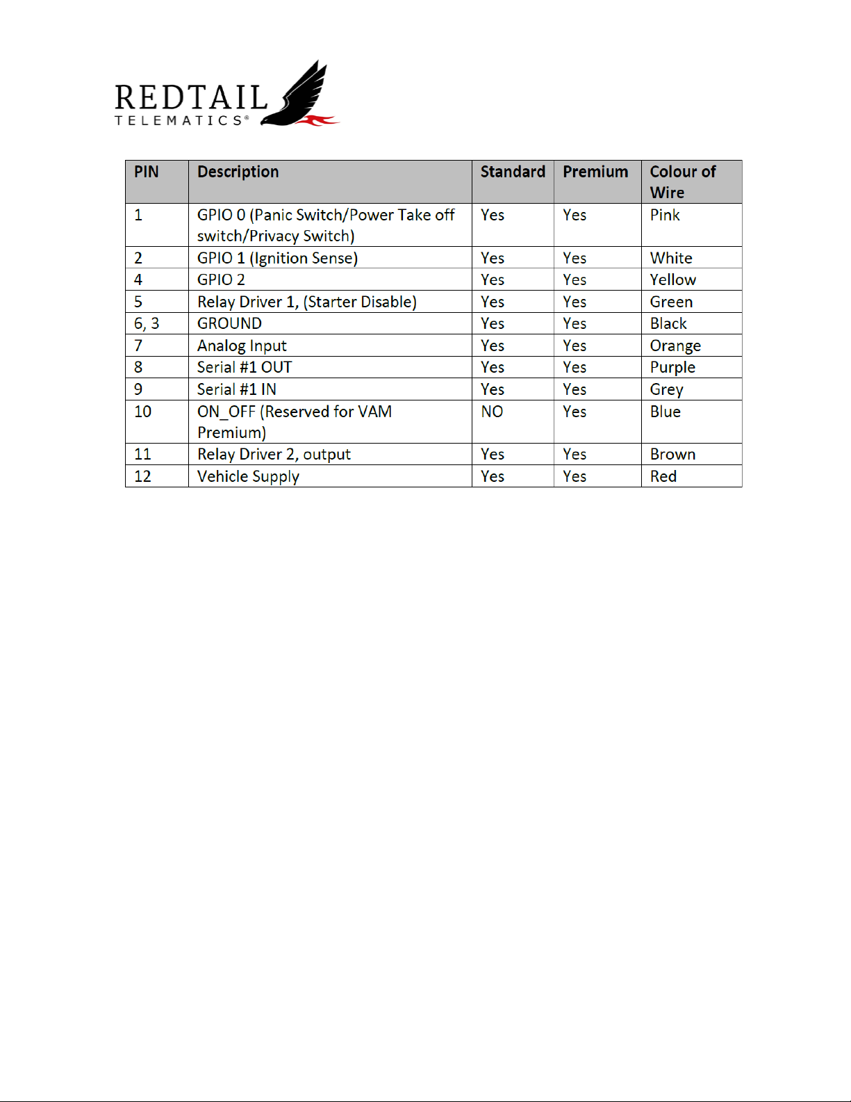
Disconnect or cut the blue wires. This will activate the internal battery.
A digital multi-meter will be needed to test the wiring. Turn your meter on to DC voltage
and Ground the black lead of the meter, you can now use the red lead of the meter to test
for your ignition and +12 volt sources.
If at all possible it is highly recommended that you locate a +12VDC or +24VDC supply in
the vehicle that is not affected by the ignition status. The simplest location to find such a
supply is a connection direct from the battery or within the ignition wiring harness. (Refer
to your specific vehicle’s wiring diagram). Connect the red wire to the permanent +12VDC
or +24VDC supply of the vehicle.
Connect the black wire to a solid chassis ground that is clean and free of paint or dirt. Use
the star washer and the self-tapping screw for this purpose
Connect the white wire on the VAM-HD Rugged harness to an ignition sense. The ignition
sense wire can be identified by grounding the black lead of the meter and probing with the
red lead of the meter.
This wire will show no voltage on the meter with the key off and when the ignition is
switched on, the ignition sense wire on the vehicle will go to 12VDC or higher.
When the ignition is turned back off, this voltage will drop back to 0V. Connect the White
wire on the VAM-HD Rugged harness to this. Once all connections have been made.
Once installed, use the remaining cable ties to tidy the wires on the system cable.
The unit is sealed to IP67. It is the responsibility of the installer to terminate the unused
wires sufficiently to stop water wicking down the ends of the wires.
1.3 Installation Testing
Park the vehicle in a fairly open area outdoors to receive GPS signals, with engine off. The
VAM unit is set to automatically search for a GPS fix as soon as power is applied. Once a fix
has been found, the unit will send a “First Fix Message” via the GSM network to the Back
Office provider.
Next turn the engine on and observe the LED flash sequence as described in the table in
section 6.
Ensure that the GPS is able to achieve a 3D fix by observing the 3 short green flashes. A
3D fix will take several minutes to achieve.
Ensure that the VAM connects to the GSM network. This can take several minutes AFTER
the 3D GPS fix is obtained. Ensure the VAM thinks the engine is running by observing the
rapid flashes. Two should be seen in green. This should take several seconds after the

©2016 REDTAIL TELEMATICS Page 6 of 7COMPANY CONFIDENTIAL
ignition is switched on. If you only get one rapid flash the device thinks that the vehicle is
not running. CHECK YOUR IGNITION CONNECTION! Turn the engine off. The VAM diagnostic
LED sequence indicates the GPS and communications network status, plus engine running
detection. These three sequences are repeated in a loop with a one second gap between
each sequence. A full engineering diagnostic cycle lasts between 4 seconds with no GPS or
GSM and no engine running to 10½ seconds with 3D GPS, GSM SMS active and the engine
running.
To save power, the LED will be switched off when the VAM is in Sleep Mode.
Diagnostic LED flash sequence
LED Flash
Colour
Type
Description
GPS
Red
1 short flash
No GPS
Orange
2 short flashes
2D GPS fix
Green
3 short flashes
3D GPS fix
GSM/GPRS Network Connection
Orange
1 medium flash
GSM network available (SMS only)
Green
2 medium flashes
Data link available (GPRS)
Orange
3 medium flashes
SMS(s) being transmitted or
received since last sequence cycle
Red
4 medium flashes
No network coverage (No GSM,
GPRS)
Ignition Status
Orange
1 rapid flash
Ignition OFF
Green
2 rapid flashes
Ignition ON
Bluetooth
Orange
1 long flash
Searching for a Bluetooth connection
Green
2 long flashes
Bluetooth connected
Red
1 long flash
Bluetooth not connected/off
Rugged Battery Replacement

©2016 REDTAIL TELEMATICS Page 7 of 7COMPANY CONFIDENTIAL
On older Rugged devices, the battery is NOT rechargeable, but replacement batteries can be
purchased by contacting REDTAIL.
The battery can be replaced by unscrewing the 8 screws around the case and separating the
two halves of the caseworks.
Once the casing is separated, simply unplug the old battery pack to remove it and plug in
the new battery pack. (see image below)
Once the battery has been replaced make sure the gasket is fit correctly prior to putting the
screws back in to ensure the device retains its dust proof and water proof qualities.
.
Other REDTAIL TELEMATICS GPS manuals