10
TRIM PROCEDURE
SSH
SSH Users Manual
retroaktiv
SQRSAW TRISIN
TRIM PROCEDURE
MIN RATE TRIM
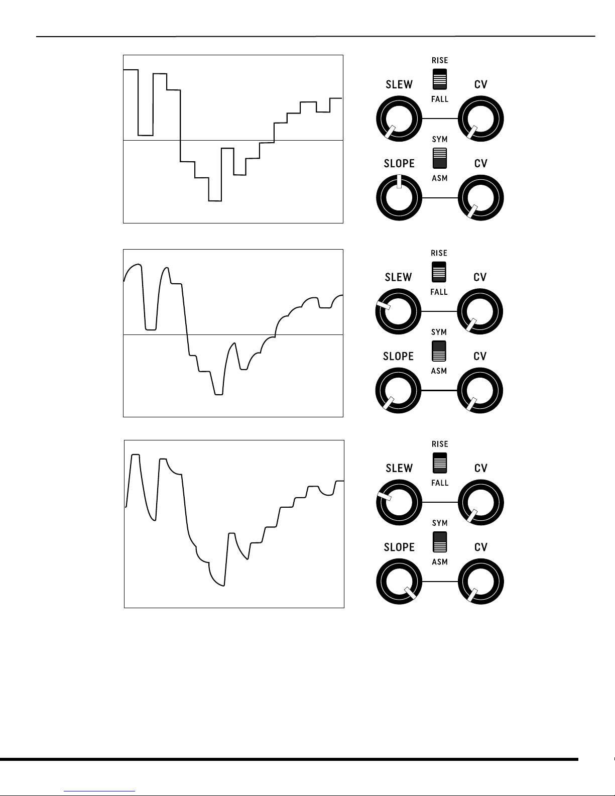
• Set front panel knobs as shown in Fig 11. RATE
should be set at minimum.
• Use the MIN RATE trimmer on the PCB to adjust the
minimum rate of the internal clock. Monitor the
rate using the panel LED indicator. If this trimmer
is set too low, the clock LFO will no longer oscillate.
A recommended minimum rate is .25Hz (period of
about 5 seconds.)
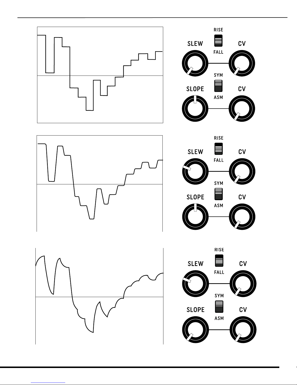
SLOPE CIRCUIT TRIM
• It is recommended that an oscilloscope be used to
monitor the SSH output signals when trimming the
SLOPE circuit. This can be done by ear as well, but
it can take more work.
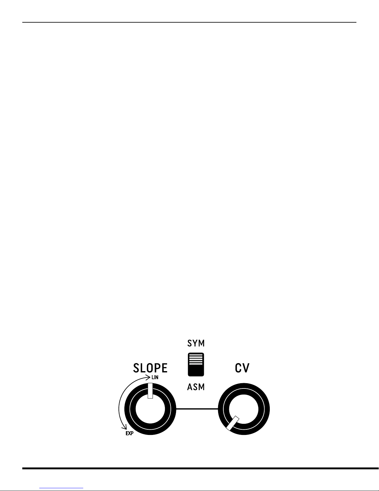
• Set the front panel knobs as shown in figure 11. Set
RATE knob to center position. Monitor the SLEW
output signal at the SLEW test point at the rear of
the SLEW output jack.
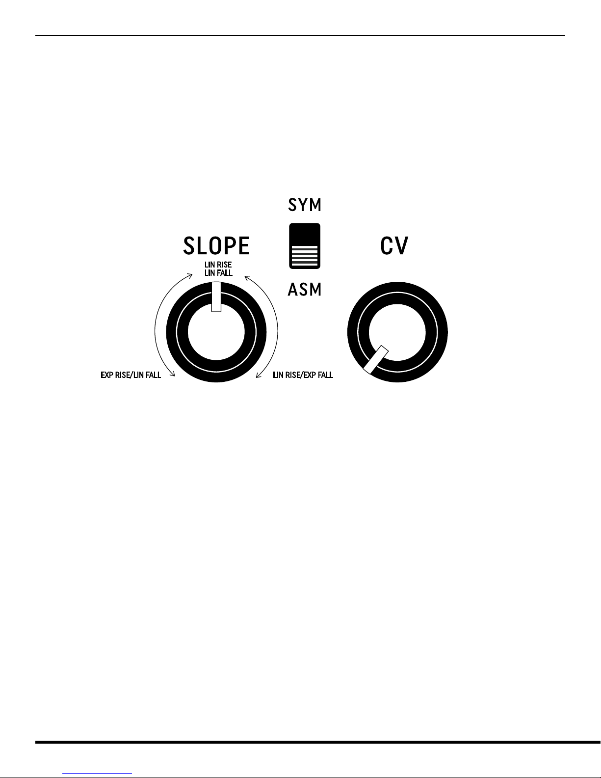
• Use the SHAPE trimmer on the PCB to dial in an
exponential waveform, then sweep the SLOPE knob
to center position. Slewing should morph from EXP
to LIN as the SLOPE knob is swept from fully count-
er-clockwise to mid-position. If the trimmer is set
too high, the slew will not be EXP when SLOPE is set
to its minumum. If the trimmer is set too low, the
slew effect will become extreme.
• When satisfied with the range of the slope knob, set
the SYM/ASM switch to ASM position. Turn SLOPE
knob fully clockwise. Monitor the SLEW output and
use the INV trimmer to trim the falling poions of
the SLEW waveform such that they match the EXP
curve set in the previous step.
• Seing SHAPE and INV can be done by ear if the
SLEW output is connected to the pitch CV input of a
VCO. Monitor the pitch and adjust the shape by ear.
Figure 11 - Panel settings for trimming