REVCO Legaci ULT2186-9-D14 User manual

-~
ARTISAN
®
~I
TECHNOLOGY
GROUP
Your definitive source
for
quality
pre-owned
equipment.
Artisan Technology
Group
Full-service,
independent
repair
center
with
experienced
engineers
and
technicians
on staff.
We
buy
your
excess,
underutilized,
and
idle
equipment
along
with
credit
for
buybacks
and
trade-ins
.
Custom
engineering
so
your
equipment
works
exactly as
you
specify.
•
Critical
and
expedited
services
•
Leasing
/
Rentals/
Demos
• In
stock/
Ready-to-ship
•
!TAR-certified
secure
asset
solutions
Expert
team
ITrust
guarantee
I
100%
satisfaction
All
tr
ademarks,
br
a
nd
names, a
nd
br
a
nd
s a
pp
earing here
in
are
th
e property of
th
e
ir
r
es
pecti
ve
ow
ner
s.
Find the Thermo / Revco ULT1786-9-D30 at our website: Click HERE

39125H01 Rev. J
©2005 Revco
All rights reserved
Printed in U.S.A
Chest and
Upright Freezers
Installation and Operation Manual
Table of Contents
About Legaci®. . . . . . . . . . . . . . . . . . . . . . . . . . . . . 1
Safety Considerations . . . . . . . . . . . . . . . . . . . . . . 1
General Recommendations . . . . . . . . . . . . . . . . . . 1
Pre-Installation . . . . . . . . . . . . . . . . . . . . . . . . . . . . 1
Installation . . . . . . . . . . . . . . . . . . . . . . . . . . . . . . . 2
Operation (Ultimaand EliteFreezers) . . . . . . . 4
Operation (ValueFreezers) . . . . . . . . . . . . . . . . . 9
Maintenance and Troubleshooting . . . . . . . . . . . . 10
Chart Recorders . . . . . . . . . . . . . . . . . . . . . . . . . . 11
Optional Equipment . . . . . . . . . . . . . . . . . . . . . . . 12
Accessories. . . . . . . . . . . . . . . . . . . . . . . . . . . . . . 12
Warranty . . . . . . . . . . . . . . . . . . . . . . . . . . . . . . . . 16
Artisan Technology Group - Quality Instrumentation ... Guaranteed | (888) 88-SOURCE | www.artisantg.com

Installation and Operation
Chest and Upright Freezers
i
Table of Contents
1 About Legaci® . . . . . . . . . . . . . . . . . . . . . . . . . . . . . . . . . . . . . . . . . . . . . . . . . . . . . . . . . . . . . . . . . . . . 1
2 Safety Precautions . . . . . . . . . . . . . . . . . . . . . . . . . . . . . . . . . . . . . . . . . . . . . . . . . . . . . . . . . . . . . . . . . 1
3 General Recommendations . . . . . . . . . . . . . . . . . . . . . . . . . . . . . . . . . . . . . . . . . . . . . . . . . . . . . . . . . . 1
3.1 Initial Loading . . . . . . . . . . . . . . . . . . . . . . . . . . . . . . . . . . . . . . . . . . . . . . . . . . . . . . . . . . . . . . . . . . . . . . . . . . . . 1
4 Pre-Installation . . . . . . . . . . . . . . . . . . . . . . . . . . . . . . . . . . . . . . . . . . . . . . . . . . . . . . . . . . . . . . . . . . . . 1
4.1 Unpacking . . . . . . . . . . . . . . . . . . . . . . . . . . . . . . . . . . . . . . . . . . . . . . . . . . . . . . . . . . . . . . . . . . . . . . . . . . . . . . .1
5 Installation . . . . . . . . . . . . . . . . . . . . . . . . . . . . . . . . . . . . . . . . . . . . . . . . . . . . . . . . . . . . . . . . . . . . . . . . 2
5.1 Location . . . . . . . . . . . . . . . . . . . . . . . . . . . . . . . . . . . . . . . . . . . . . . . . . . . . . . . . . . . . . . . . . . . . . . . . . . . . . . . .2
5.2 Wiring . . . . . . . . . . . . . . . . . . . . . . . . . . . . . . . . . . . . . . . . . . . . . . . . . . . . . . . . . . . . . . . . . . . . . . . . . . . . . . . . . . 2
5.3 Leveling . . . . . . . . . . . . . . . . . . . . . . . . . . . . . . . . . . . . . . . . . . . . . . . . . . . . . . . . . . . . . . . . . . . . . . . . . . . . . . . .2
5.4 Door Operation (Upright Models) . . . . . . . . . . . . . . . . . . . . . . . . . . . . . . . . . . . . . . . . . . . . . . . . . . . . . . . . . . . . .3
5.4.1 Opening the Door . . . . . . . . . . . . . . . . . . . . . . . . . . . . . . . . . . . . . . . . . . . . . . . . . . . . . . . . . . . . . . . . . .3
5.4.2 Closing the Door . . . . . . . . . . . . . . . . . . . . . . . . . . . . . . . . . . . . . . . . . . . . . . . . . . . . . . . . . . . . . . . . . . .3
5.5 Pressure Equalization Port . . . . . . . . . . . . . . . . . . . . . . . . . . . . . . . . . . . . . . . . . . . . . . . . . . . . . . . . . . . . . . . . . .3
6 Operation (Ultima II-9 and Elite-5 Freezers) . . . . . . . . . . . . . . . . . . . . . . . . . . . . . . . . . . . . . . . . . . . . . 4
6.1 Control Panel Features . . . . . . . . . . . . . . . . . . . . . . . . . . . . . . . . . . . . . . . . . . . . . . . . . . . . . . . . . . . . . . . . . . . . .4
6.2 Start Up . . . . . . . . . . . . . . . . . . . . . . . . . . . . . . . . . . . . . . . . . . . . . . . . . . . . . . . . . . . . . . . . . . . . . . . . . . . . . . . .5
6.2.1 Turning the Power On . . . . . . . . . . . . . . . . . . . . . . . . . . . . . . . . . . . . . . . . . . . . . . . . . . . . . . . . . . . . . . .5
6.2.2 Setting the Cabinet Temperature . . . . . . . . . . . . . . . . . . . . . . . . . . . . . . . . . . . . . . . . . . . . . . . . . . . . . . .5
6.2.3 Setting the Alarms . . . . . . . . . . . . . . . . . . . . . . . . . . . . . . . . . . . . . . . . . . . . . . . . . . . . . . . . . . . . . . . . . .5
6.2.4 Alarm Reset & Status Lights (Ultima II and Elite Freezers) . . . . . . . . . . . . . . . . . . . . . . . . . . . . . . . . . . .5
6.2.5 Alarm Test (Ultima II and Elite Freezers) . . . . . . . . . . . . . . . . . . . . . . . . . . . . . . . . . . . . . . . . . . . . . . . . .6
6.3 Backup System (Optional) . . . . . . . . . . . . . . . . . . . . . . . . . . . . . . . . . . . . . . . . . . . . . . . . . . . . . . . . . . . . . . . . . .6
6.3.1 CO2and LN2Precautions . . . . . . . . . . . . . . . . . . . . . . . . . . . . . . . . . . . . . . . . . . . . . . . . . . . . . . . . . . . . 6
6.3.2 Installation . . . . . . . . . . . . . . . . . . . . . . . . . . . . . . . . . . . . . . . . . . . . . . . . . . . . . . . . . . . . . . . . . . . . . . . .7
6.3.3 Operation . . . . . . . . . . . . . . . . . . . . . . . . . . . . . . . . . . . . . . . . . . . . . . . . . . . . . . . . . . . . . . . . . . . . . . . . .7
6.3.4 System Status Lights . . . . . . . . . . . . . . . . . . . . . . . . . . . . . . . . . . . . . . . . . . . . . . . . . . . . . . . . . . . . . . . . 7
7 Operation (Value Freezers) . . . . . . . . . . . . . . . . . . . . . . . . . . . . . . . . . . . . . . . . . . . . . . . . . . . . . . . . . . 9
7.1 Control Panel Features . . . . . . . . . . . . . . . . . . . . . . . . . . . . . . . . . . . . . . . . . . . . . . . . . . . . . . . . . . . . . . . . . . . . .9
7.2 Start Up . . . . . . . . . . . . . . . . . . . . . . . . . . . . . . . . . . . . . . . . . . . . . . . . . . . . . . . . . . . . . . . . . . . . . . . . . . . . . . . .9
7.2.1 Turning the Power On . . . . . . . . . . . . . . . . . . . . . . . . . . . . . . . . . . . . . . . . . . . . . . . . . . . . . . . . . . . . . . .9
7.2.2 Setting the Cabinet Temperature . . . . . . . . . . . . . . . . . . . . . . . . . . . . . . . . . . . . . . . . . . . . . . . . . . . . . . .9
7.2.3 Optional Alarm . . . . . . . . . . . . . . . . . . . . . . . . . . . . . . . . . . . . . . . . . . . . . . . . . . . . . . . . . . . . . . . . . . . . . 9
Artisan Technology Group - Quality Instrumentation ... Guaranteed | (888) 88-SOURCE | www.artisantg.com

Installation and Operation
Chest and Upright Freezers
ii
8 Operation (Countertop Freezers) . . . . . . . . . . . . . . . . . . . . . . . . . . . . . . . . . . . . . . . . . . . . . . . . . . . . 10
8.1 Control Panel Features . . . . . . . . . . . . . . . . . . . . . . . . . . . . . . . . . . . . . . . . . . . . . . . . . . . . . . . . . . . . . . . . . . . .10
8.2 Start Up . . . . . . . . . . . . . . . . . . . . . . . . . . . . . . . . . . . . . . . . . . . . . . . . . . . . . . . . . . . . . . . . . . . . . . . . . . . . . . .10
8.2.1 Turning the Power On . . . . . . . . . . . . . . . . . . . . . . . . . . . . . . . . . . . . . . . . . . . . . . . . . . . . . . . . . . . . . .10
8.2.2 Setting the Cabinet Temperature . . . . . . . . . . . . . . . . . . . . . . . . . . . . . . . . . . . . . . . . . . . . . . . . . . . . . .10
8.2.3 Warm Alarm . . . . . . . . . . . . . . . . . . . . . . . . . . . . . . . . . . . . . . . . . . . . . . . . . . . . . . . . . . . . . . . . . . . . .10
9 Maintenance and Troubleshooting . . . . . . . . . . . . . . . . . . . . . . . . . . . . . . . . . . . . . . . . . . . . . . . . . . . 11
9.1 Condenser Maintenance . . . . . . . . . . . . . . . . . . . . . . . . . . . . . . . . . . . . . . . . . . . . . . . . . . . . . . . . . . . . . . . . . . 11
9.1.1 Cleaning the Condenser . . . . . . . . . . . . . . . . . . . . . . . . . . . . . . . . . . . . . . . . . . . . . . . . . . . . . . . . . . . .11
9.1.2 Cleaning the Condenser Filter . . . . . . . . . . . . . . . . . . . . . . . . . . . . . . . . . . . . . . . . . . . . . . . . . . . . . . . .11
9.2 Gasket Maintenance . . . . . . . . . . . . . . . . . . . . . . . . . . . . . . . . . . . . . . . . . . . . . . . . . . . . . . . . . . . . . . . . . . . . . .11
9.3 Defrost Procedures . . . . . . . . . . . . . . . . . . . . . . . . . . . . . . . . . . . . . . . . . . . . . . . . . . . . . . . . . . . . . . . . . . . . . . .11
9.4 Alarm Battery Maintenance . . . . . . . . . . . . . . . . . . . . . . . . . . . . . . . . . . . . . . . . . . . . . . . . . . . . . . . . . . . . . . . .11
9.5 Troubleshooting Procedures . . . . . . . . . . . . . . . . . . . . . . . . . . . . . . . . . . . . . . . . . . . . . . . . . . . . . . . . . . . . . . . .11
10 Chart Recorders . . . . . . . . . . . . . . . . . . . . . . . . . . . . . . . . . . . . . . . . . . . . . . . . . . . . . . . . . . . . . . . . . . 12
10.1Set Up and Operation . . . . . . . . . . . . . . . . . . . . . . . . . . . . . . . . . . . . . . . . . . . . . . . . . . . . . . . . . . . . . . . . . . . . .12
10.2Power Supply . . . . . . . . . . . . . . . . . . . . . . . . . . . . . . . . . . . . . . . . . . . . . . . . . . . . . . . . . . . . . . . . . . . . . . . . . . .12
10.3Changing Chart Paper . . . . . . . . . . . . . . . . . . . . . . . . . . . . . . . . . . . . . . . . . . . . . . . . . . . . . . . . . . . . . . . . . . . .12
10.4Calibration Adjustment . . . . . . . . . . . . . . . . . . . . . . . . . . . . . . . . . . . . . . . . . . . . . . . . . . . . . . . . . . . . . . . . . . . .12
11 Optional Equipment . . . . . . . . . . . . . . . . . . . . . . . . . . . . . . . . . . . . . . . . . . . . . . . . . . . . . . . . . . . . . . . 13
11.1Backup Protection Devices . . . . . . . . . . . . . . . . . . . . . . . . . . . . . . . . . . . . . . . . . . . . . . . . . . . . . . . . . . . . . . . . .13
11.1.1 Liquid Nitrogen (LN2) . . . . . . . . . . . . . . . . . . . . . . . . . . . . . . . . . . . . . . . . . . . . . . . . . . . . . . . . . . . . . . .13
11.1.2 Liquid CO2 . . . . . . . . . . . . . . . . . . . . . . . . . . . . . . . . . . . . . . . . . . . . . . . . . . . . . . . . . . . . . . . . . . . . . . . 13
11.1.3 Voltage Safeguard . . . . . . . . . . . . . . . . . . . . . . . . . . . . . . . . . . . . . . . . . . . . . . . . . . . . . . . . . . . . . . . . .13
11.2Remote Alarm . . . . . . . . . . . . . . . . . . . . . . . . . . . . . . . . . . . . . . . . . . . . . . . . . . . . . . . . . . . . . . . . . . . . . . . . . . .13
12 Accessories . . . . . . . . . . . . . . . . . . . . . . . . . . . . . . . . . . . . . . . . . . . . . . . . . . . . . . . . . . . . . . . . . . . . . . 13
13 Warranty . . . . . . . . . . . . . . . . . . . . . . . . . . . . . . . . . . . . . . . . . . . . . . . . . . . . . . . . . . . . . . . . . . . . . . . . 17
13.1Domestic Warranty
13 Months Full Warranty, Parts and Labor
United States of America and Canada . . . . . . . . . . . . . . . . . . . . . . . . . . . . . . . . . . . . . . . . . . . . . . . . . . . . . . . . 17
13.2International Warranty
16 Month Parts Warranty . . . . . . . . . . . . . . . . . . . . . . . . . . . . . . . . . . . . . . . . . . . . . . . . . . . . . . . . . . . . . . . . . .17
13.3Extended Warranty Options . . . . . . . . . . . . . . . . . . . . . . . . . . . . . . . . . . . . . . . . . . . . . . . . . . . . . . . . . . . . . . . .17
Artisan Technology Group - Quality Instrumentation ... Guaranteed | (888) 88-SOURCE | www.artisantg.com

Installation and Operation
Chest and Upright Freezers
1
1 About Legaci®
All of the Revco ultra-low temperature freezers described in this
manual feature the Legacirefrigeration system, a combination
of advanced technologies designed specifically to provide
optimal reliability in low-temperature applications.
Legaci systems include:
•Copeland compressors custom-designed for Revco to
minimize bearing wear and operate efficiently under heavy
work loads
•Dupont Suvarefrigerants selected to provide maximum
cooling capacity under low-temperature conditions
•Revco’s field-proven cascade refrigeration system design.
All upright models include a pressure equalization port to combat
the vacuum created after door openings.
2 Safety Precautions
In this manual and on labels attached to this product, the words
WARNING and CAUTION mean the following:
•WARNING: a potentially hazardous situation which, if not
avoided, could result in serious injury or death.
•CAUTION: a potentially hazardous situation which, if not
avoided, may result in minor or moderate injury or damage to
the equipment.
Before installing, using or maintaining this product, please be sure
to read this manual and product warning labels carefully. Failure to
follow these instructions may cause this product to malfunction,
which could result in injury or damage.
Below are important safety precautions that apply to this product:
•Use this product only in the way described in the product
literature and in this manual. Before using it, verify that this
product is suitable for its intended use.
•Do not modify system components, especially the controller.
Use OEM exact replacement equipment or parts. Before use,
confirm that the product has not been altered in any way.
•Your unit must be properly grounded in conformity with
national and local electrical codes. Never connect the unit to
overloaded power sources.
•Disconnect the unit from all power sources before cleaning,
troubleshooting, or performing other maintenance on the
product or its controls.
3 General Recommendations
The refrigeration system is designed to maintain ultra-low
temperatures with safety in a +32C (90F) ambient
environment, only when the freezer is used for storage.
WARNING! This unit is not a “rapid-freeze” device.
Freezing large quantities of liquid, or high-water
content items, will temporarily increase the chamber
temperature and will cause the compressors to
operate for a prolonged time period. Attempting to
utilize this freezer improperly may jeopardize safety or
cause undue stress or damage to the refrigeration
compressors.
Avoid opening the door for extended time periods since chamber
temperature air will escape rapidly. Room air, which is higher in
humidity, replacing chamber air may cause frost to develop in the
chamber more rapidly.
After reading and completing the Safety Considerations,
Pre-Installation, Installation, and Operation sections of this
manual, turn the Key Switch to the POWER ON position.
3.1 Initial Loading
When loading the unit with “pre-frozen” materials, the operating
temperature setpoint of the freezer should be set no lower than
the temperature of the “pre-frozen” material. Allow the unit to
operate at the setpoint for eight hours. The setpoint may then be
lowered in increments no greater than 10ºC. Allow a stabilizing
period of eight hours for each ten degree adjustment, until the
desired setpoint is achieved.
CAUTION! Failure to follow these procedures or
overloading the unit may cause undue stress on the
compressors or jeopardize user product safety.
4 Pre-Installation
4.1 Unpacking
At delivery, examine the exterior for physical damage while the
carrier’s representative is present. If exterior damage is
present, carefully unpack and inspect the unit and all
accessories for damage.
If there is no exterior damage, unpack and inspect the
equipment within five days of delivery. If you find any damage,
keep the packing materials and immediately report the damage
to the carrier. Do not return goods to Revco without written
authorization. When submitting a claim for shipping damage,
request that the carrier inspect the shipping container and
equipment.
CAUTION! Do not discard the sublids from
chest-style units. The sublids are necessary to
maintain correct temperature, moisture control, and
economy of operation. Upright models do not include
sublids as they utilize built-in metal inner doors.
Artisan Technology Group - Quality Instrumentation ... Guaranteed | (888) 88-SOURCE | www.artisantg.com

Installation and Operation
Chest and Upright Freezers
2
5 Installation
Do not exceed the electrical and temperature ratings printed on
the dataplate located on the lower left side of the unit.
CAUTION! Improper operation of the equipment
could result in dangerous conditions. To preclude
hazard and minimize risk, follow all instructions and
operate within the design limits noted on the
dataplate.
5.1 Location
Install the unit in a level area free from vibration with a minimum
of six inches of space on the sides, rear, and top. Refer to
Section 5.3 for further instructions on leveling cabinets. Allow
enough clearance so that door or lid can swing open at least
90 degrees.
Do not position the equipment in direct sunlight or near heating
diffusers, radiators, or other sources of heat. The ambient
temperature range at the location must be 59 to 90F
(15 to 32C).
CAUTION! To allow for proper air flow, a minimum
of six inches of clearance space is required behind the
freezer.
5.2 Wiring
CAUTION! Connect the equipment to the correct
power source. Incorrect voltage can result in severe
damage to the equipment.
CAUTION! For personal safety and trouble-free
operation, this unit must be properly grounded before
it is used. Failure to ground the equipment may cause
personal injury or damage to the equipment. Always
conform to the National Electrical Code and local
codes. Do not connect the unit to overloaded power
lines.
Your freezer is equipped with one of five NEMA style plugs
(refer to Figure 1). These plugs meet UL requirements.
Figure 1. NEMA Style Plugs
Always connect the freezer to a dedicated (separate) circuit. Each
freezer is equipped with a service cord and plug designed to
connect it to a power outlet which delivers the correct voltage.
Supply voltage must be within +10%, -5% of the freezer rated
voltage.
If you have known voltage stability problems which are outside
the limits of the freezer rated voltage, we recommended that the
freezer be equipped with a Voltage Safeguard. Order the Voltage
Safeguard from Revco (refer to Section 10.1.3 on page 12 for
ordering information).
Note: Revco 900 Series freezers are equipped with a standard
built-in Voltage Safeguard circuit to detect and adjust
low line voltage.
CAUTION! Never cut the grounding prong from the
service cord plug. If the prong is removed, the
warranty is invalidated.
5.3 Leveling
The unit must be level both front to back and side to side.
To level chest models, leave the casters in place and shim the low
wheel(s) with strips of sheet metal cut at least 1/2 in. wider than
the caster.
Upright models have adjustable leveling feet which are located
adjacent to the front casters.
15A-125V
NEMA 5-15P
20A-125V
NEMA 5-20P
15A-250V
NEMA 6-15P
20A-250V
NEMA 6-20P
30A-250V
NEMA 6-30P
Artisan Technology Group - Quality Instrumentation ... Guaranteed | (888) 88-SOURCE | www.artisantg.com

Installation and Operation
Chest and Upright Freezers
3
5.4 Door Operation (Upright Models)
Revco upright freezer models are equipped with an advanced
Cryolatch™assembly specifically designed for ultra-low
temperature freezers.
Features include:
•One-hand operation
•A front-accessible lock, keyed to match the freezer control
lock
•Hasps for a standard padlock to provide additional security
•Durable construction for reliable operation and safe product
storage.
CAUTION! When moving the freezer, always grasp
cabinet surfaces; never pull the freezer by the latch
handle.
5.4.1 Opening the Door
1. Remove the padlock if you have one.
2. Move the key into the open position by rotating it counter-
clockwise.
3. Grasp the latch handle (preferably with your left hand) and
pull it toward yourself until the latch disengages from the
cabinet strike.
4. Keep pulling by the latch handle or the integrated door
handle to open the main door.
5.4.2 Closing the Door
Note that the latch does not self-engage automatically when you
close the door. You must rotate the latch into the open position
first.
1. Grasp the latch handle (preferably with your left hand) and
pull it toward yourself, rotating the latch into the open
position.
2. Move the freezer door into the closed position and gently
push the handle away from you, making sure that the latch
engages fully with the cabinet strike.
CAUTION! Closing the door without making sure
the latch engages fully with the strike can result in
substantial prying forces on the door.
3. Keep applying gentle pressure to the latch handle until the
latch is securely in closed position.
4. Insert the key and rotate clockwise to lock.
5. Replace the padlock if you are using one.
5.5 Pressure Equalization Port
When an upright ultra-low temperature freezer door is opened,
room temperature air rushes into the storage compartment.
When the door is closed, the fixed volume of air is cooled rapidly.
Pressure drops below atmospheric pressure, resulting in a
substantial vacuum. Re-entry into the cabinet is impossible until
internal pressures are returned to atmospheric pressure. Without a
pressure equalization mechanism, it can take several minutes
before the door can easily be reopened.
All upright models feature a port that provides vacuum relief
after door openings.
The pressure equalization port is located in the bottom left side of
the storage chamber. Although the port is designed to self-
defrost, excessive frost accumulation in the bottom of the
chamber could eventually restrict air flow. Therefore you should
periodically inspect the port and brush away any loose frost using
a stiff nylon brush.
WARNING! To ensure proper operation, be sure not
to obstruct the port. Push any storage racks near the
port all the way to the rear of the cabinet.
WARNING! When the freezer is in operation, avoid
touching the lower left side of the cabinet exterior near
the “hot surface” warning label. The port can get hot
immediately after it is activated.
Artisan Technology Group - Quality Instrumentation ... Guaranteed | (888) 88-SOURCE | www.artisantg.com

Installation and Operation
Chest and Upright Freezers
4
6 Operation (Ultima II-9 and Elite-5 Freezers)
6.1 Control Panel Features
Figure 2. Ultima II 900 Series Control Panel with Optional Backup System
off
life-guard alert extreme ambient alert
clean filter
power failure
temperature failure
alarm test alarm reset
cabinet
temperature
control
set point
alarm
battery low
voltage
warm alarm
set point
cold alarm
set point
power on
alarm on
set point security
Ultima
1157 9 10
11
SUPPLY
ON
SUPPLY
EMPTY
BACKUP SYSTEM
BATTERY
LOW
823
612 13 2120 22
14 1819
17
16
2
543
check
fuse
boost
Before the initial start up, take some time to become familiar
with the controls on your freezer. Figure 2 illustrates the Revco
Ultima II Chest and Upright Freezer control panel.
Note: Figure 2 shows all possible functions. These functions
vary depending on the model and options. You may not
have all of the functions on your equipment. Elite models
do not include the Check Fuse indicator light (6) or the
Voltage Boost light (19) as these models do not come
standard with these options. Likewise, only Ultima II
models will include the Set Point Security feature (23),
Life-Guard Alert indicator light (5), and the Extreme
Ambient Alert indicator light (16). The CO2or LN2
Backup System lights (20, 21, 22) represent status
indicators for a built-in CO2or LN2backup system,
which is optional on Ultima II and Elite models.
1. Three position keyed Power On Switch.
2. Power On Indicator. This indicator lights when power is
connected to the freezer.
3. Temperature Failure Indicator. This indicator lights when the
freezer temperature deviates either above or below the alarm
temperature settings.
4. Power Failure Indicator. This indicator lights when there is a
power failure to the freezer (refer to Section 8 on page 10).
5. Life-Guard Alert Indicator (Ultima II Models only.) This
indicator lights when the first stage compressor has gone into
a cautionary state of operation to help prevent failure.
6. Check Fuse Light (Ultima II and Ultima Models only). This
indicator lights when the surge protector on the main
electronic panel is blown by a power surge (refer to Section 8
on page 10).
7. Alarm Test Pad. Press this pad to start an alarm test (refer to
Section 5.2.5 on page 6).
8. Alarm Reset Pad. Press this pad to reset slowly blinking
indicators. Slowly blinking indicators denote that the
condition has occurred but is now within the given operating
parameters. This pad is also depressed to temporarily silence
the audible alarm (refer to Section 6.2.4 on page 5).
9. Cold Alarm Setpoint. Press this pad to set the cold alarm
(refer to Section 6.2.3 on page 5).
10. Warm Alarm Setpoint. Press this pad to set the warm alarm
(refer to Section 6.2.3 on page 5).
11. Control Setpoint. Press this pad to set the cabinet temperature
(refer to Section 6.2.2 on page 5).
12. Cabinet Temperature Indicator. This indicator lights when the
temperature display window is showing the cabinet
temperature (refer to Section 6.2.1 on page 5).
13. Digital Temperature Display Window. This window displays
chamber temperature, alarm values, etc. depending on the
operating status of the freezer and the procedure being
performed.
14. Decrement Pad ( ). Use this pad to decrease temperature
values.
15. Increment Pad ( ). Use this pad to increase temperature
values.
16. Extreme Ambient Alert (Ultima II Models only). This
indicator lights when the ambient temperature has exceeded
the upper limit of the recommended operating range. If the
Extreme Ambient Alert is activated, the ambient
environment needs to be improved for proper function of the
freezer.
17. Clean Filter Indicator. This indicator lights when the air
cooled condenser filter is dirty (refer to Section 8 on
page 10).
18. Alarm Battery Low Indicator. This indicator lights when the
charge on the alarm battery is low. Press this button to
display the percent of full battery charge in the digital display
window.
19. Voltage Boost Indicator. This indicator lights when incoming
voltage is low and the Voltage Safeguard has been activated
(refer to Section 8 on page 10). Press this pad to display the
current line voltage in the digital display window.
23. Alarm On/Set Point Security Indicator. This indicator lights
when the alarm is activated.Also indicates that Setpoint
Security is activated (Ultima II Models only).
Artisan Technology Group - Quality Instrumentation ... Guaranteed | (888) 88-SOURCE | www.artisantg.com

Installation and Operation
Chest and Upright Freezers
5
The following indicators are available only when the freezer is
equipped with the optional backup system (refer to Section 6.3.4
on page 7).
20. Backup System Supply On Indicator.
21. Backup System Empty Indicator
22. Backup System Battery Low Indicator.
6.2 Start Up
Refer to Section 6.1 and Figure 2 on page 4 as you complete the
following procedures.
6.2.1 Turning the Power On
To start up the Ultima 900, Ultima 700 and Elite 500 Series
Freezers, complete the following steps:
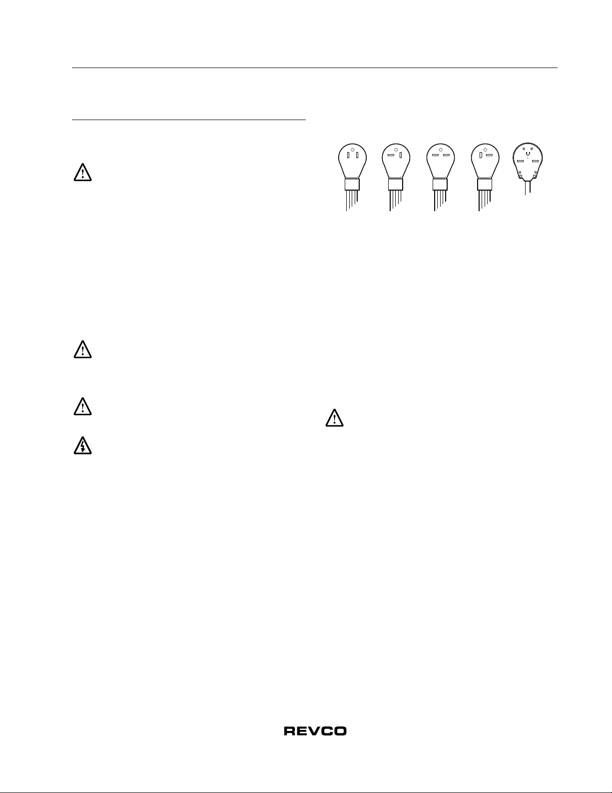
1. Plug the freezer into the power outlet (refer to Section 4.2 on
page 2).
2. Turn the key switch to the POWER ON position. The Power
On LED and the Cabinet Temperature LED illuminate.
Note: The alarm function is not active at this time. Refer to
Section 5.2.3 for information about setting the alarms. In
addition, for Ultima II units only, the Setpoint Security
will be deactivated in this key position.
6.2.2 Setting the Cabinet Temperature
To set the cabinet temperature, complete the following steps:
1. For Ultima II units, press and hold the Control Setpoint pad.
2. The Control setpoint LED lights and the Cabinet
Temperature LED goes out.
3. Press and hold to increase the temperature or to
decrease the temperature. The digital display scrolls through
temperature settings.
4. Release both pads when the digital temperature display
window shows the correct setpoint value.
Note: If no keys are pressed within ten seconds, the
temperature display reverts to the cabinet temperature.
6.2.3 Setting the Alarms
To set the cold alarm, complete the following steps:
1. For Ultima II units only, confirm that the key switch is at the
Power On position (Setpoint Security disabled)
2. Press and hold the Cold Alarm Setpoint pad. The LED next
to this pad lights. The temperature display shows the Cold
Alarm value.
3. Press and hold or to adjust the Cold Alarm Setpoint.
4. Release both pads when the digital temperature display
window shows the correct setpoint value.
To set the warm alarm, complete the following steps:
1. For Ultima II units only, confirm that the key switch is at the
Power On position (Setpoint Security disabled).
2. Press and hold the Warm Alarm Setpoint pad. The LED next
to this pad lights. The temperature display shows the Warm
Alarm value.
3. Press and hold or to adjust the Warm Alarm Setpoint.
4. Release both pads when the digital temperature display
window shows the correct setpoint value.
When the cabinet temperature drops below the Warm Alarm
setting, turn the key switch to ALARM ON. The freezer is ready
to operate.
Note: If a power failure lasting over 30 seconds occurs, the
POWER ON light goes out, the POWER FAILURE light
and digital temperature display flash simultaneously,
and a buzzer sounds.
WARNING! You must turn the three-position key
switch to the ALARM ON/SETPOINT SECURITY
position to activate the alarm and place it in security
operation.
6.2.4 Alarm Reset & Status Lights (Ultima II and Elite
Freezers)
The alarm reset feature ensures user acknowledgment of the
occurrence of certain alarm conditions. This provides greater
monitoring power by alerting the user if an alarm condition has
occurred during periods when the freezer must be left
unattended. The alarm conditions incorporating this feature are:
•Temperature Failure-Warm Alarm
•Temperature Failure-Cold Alarm
•Voltage Low
•Power Failure
•Life-Guard Alert (Ultima II only)
•Extreme Ambient Alert (Ultima II only)
During any of these alarm conditions, the corresponding
indicator will flash quickly, approximately 90 times per minute.
If the alarm condition then disappears, the flash rate will
decrease to approximately 15 times per minute. The indicator
will then remain flashing at this rate, unless the condition
reoccurs, until the Alarm Reset button is pressed. Once this has
occurred, the indicator will no longer be lit.
In the case of TEMPERATURE FAILURE-WARM ALARM and
TEMPERATURE FAILURE-COLD ALARM, if these
conditions have occurred but are now within the given limits, the
two indicators will alternately flash (180° out of phase). In
addition, for these two temperatures failures, the highest
temperature and lowest temperature, respectively, during the
error condition will be saved. Prior to the temperature failure
being reset, the temperature extreme may be viewed by pressing
the Cabinet Temperature pad in conjunction with either the
Warm Alarm Setpoint pad or the Cold Alarm Setpoint pad.
Note: Once the Alarm Reset button is depressed, the extreme
temperature value is reset to the current cabinet
temperature.
6.2.5 Alarm Test (Ultima II and Elite Freezers)
To test the cold and warm alarms, complete the following steps:
Artisan Technology Group - Quality Instrumentation ... Guaranteed | (888) 88-SOURCE | www.artisantg.com

Installation and Operation
Chest and Upright Freezers
6
1. Press and hold the Alarm Test pad. The digital temperature
display indicates rising temperature. When the temperature
reaches the warm alarm value, the alarm sounds.
Note: The temperature of the refrigerated space does not
change during this procedure. Only the sensor is heated.
2. Release the Alarm Test pad, the sensor and display return to
cabinet temperature in a few minutes.
You can press the Audio Silence pad to silence the alarm but the
alarm will ring back in five to seven minutes. You can silence the
alarm in this manner as many times as necessary until the sensor
cools below the warm alarm temperature. The alarm quits
automatically when the sensor cools below the warm alarm
value.
Note: There is a limit on the alarm test feature. The alarm test
will not commence if the warm alarm setpoint is more
than 15 degrees warmer than the operating temperature
setpoint.
6.3 Backup System (Optional)
When you purchase a built-in CO2or LN2optional backup
system for the freezer, the backup system control panel is located
behind a hinged panel adjacent to the grill (refer to Figure 3).
Note: Always purchase the cylinders which are equipped with
siphon tubes for withdrawing liquid from the bottom of
the cylinder. CO2cylinders must be kept at room
temperature to function properly. LN2 bottles are
functional at any reasonable temperature.
Use this panel to set the backup initiation temperature, usually
10 to 15C warmer than the operating setpoint.
Figure 3. Control Panel for Optional
Built-In Backup System
Note: Value Series units use free-standing, field installed
Backup Systems.
TEMPERATURE °C
PUSH
TO SET
SETPOINT
ADJUST
POWER
OFF
ON
Power
Switch
Temperature Control
Setpoint Screw
Temperature Control
Set Button
Digital Temperature
Display
Calibration Pot.
6.3.1 CO2and LN2Precautions
The following are precautions for using liquid CO2and LN2
backup systems.
WARNING! If a CO2or LN2cylinder falls and a
valve is knocked off, the cylinder becomes a deadly
and completely unguided missile. Transport the
cylinders in a handtruck or cart with secure chain ties
for the cylinder. After cylinders are connected to the
equipment, securely attach them with chains to a
solid, stationary object such as a building column.
WARNING! CO2and LN2liquids are non-poisonous
but are very cold and will burn unprotected skin.
Always wear protective eyewear and clothing when
changing cylinders or working on the piping systems
attached to an active source of liquid refrigerant.
WARNING! The gases produced by evaporation of
CO2or LN2are non-poisonous but displace the
oxygen in a confined space and can cause
asphyxiation. Do not store the cylinders in subsurface
or enclosed areas.
CAUTION! When closing the cylinder valve, make
sure that the injection solenoid is energized to allow all
the liquid to bleed off instead of being trapped in the
supply tubing. Failure to do this results in activation of
the pressure relief device, which could damage the
freezer and requires replacing if it is activated.
CAUTION! For chest and upright models ordered
with factory installed built-in backup systems, the flow
of liquid CO2or LN2will be discontinued if the door or
lid is opened during operation of the backup system.
For units operated with free-standing, field installed
type backup system, the flow of liquid CO2or LN2will
be discontinued upon door or lid opening only if the
switch provided with the free-standing package is
installed on the freezer.
Artisan Technology Group - Quality Instrumentation ... Guaranteed | (888) 88-SOURCE | www.artisantg.com

Installation and Operation
Chest and Upright Freezers
7
6.3.2 Installation
Field installed systems are supplied with complete installation
and operating instructions. If your system is factory installed, the
freezer is shipped with a coiled length of tubing to connect the
freezer to the bottles:
•3/8 in. OD copper tubing for connection to the CO2supply.
•5/8 in. OD copper tubing covered with Armaflexinsulating
tubing for connection to the LN2 supply.
Straighten the coiled tubing and connect one end to the labeled
connection on the freezer and the other end to the supply bottle or
building supply fitting.
6.3.3 Operation
To activate the optional backup system, complete the following
steps:
1. Push the Power Switch to the ON position. The digital
temperature display window shows the current cabinet
temperature.
2. Press and hold the Push to Set button to display the setpoint
temperature in the digital temperature display window.
3. Use a small screwdriver to rotate the Setpoint Adjust screw
until the correct backup operating temperature shows in the
display window. The recommended setpoint is 10 to 15C
above normal cabinet temperature.
Note: The temperature shown in the display window is
accurate to 1C.
The backup system can run for a minimum of eight hours on
battery power.
WARNING! You must push the Power Switch to the
ON position in order to activate the backup system.
6.3.4 System Status Lights
In addition to the backup control system, the built-in backup
system includes main control panel system status lights. These
lights are only available when the backup system is installed.
•The Supply On Indicator lights when the backup system is
operating on battery power.
•The Backup System Battery Low Indicator lights when the
backup system battery charge is low. The built-in battery
charger recharges the battery to full charge when power is
restored to the system.
Note: Since rechargeable batteries degrade over time, the
battery should be replaced after approximately three
years.
•The Backup System Empty Indicator lights when the standby
CO2or LN2bottle is empty.
Figure 4. Location of CO2Connection Site,
Chest Models Only
Table 1. Backup System Flow Rates – Cryogenic Freezers
Lbs/hr @ 75F
Ambient Temperature
(Flow Rate)
Center Air
Temperature -150C -140C-130C-120C
Liquid LN2
Chest Freezers
5 ft3
Empty 11.0 9.5 8.4 7.3
1/2 Full 9.3 8.0 7.0 6.1
Full 6.5 5.9 5.1 4.5
7 ft3
Empty 11.3 10.0 9.0 8.0
1/2 Full 9.7 8.6 7.6 6.8
Full 7.8 6.8 6.0 5.2
10 ft3
Empty 15.2 13.5 11.9 10.3
1/2 Full 12.0 10.4 9.4 8.3
Full 8.9 7.8 7.0 6.1
24.75"
2.375"
CO2Inlet Conn.
Copper Tubing
Factory Supplied
0.25" O.D.
MACHINE COMPARTMENT
REAR VIEW
Artisan Technology Group - Quality Instrumentation ... Guaranteed | (888) 88-SOURCE | www.artisantg.com

8
Installation and Operation
Chest and Upright Freezers
Table 2. Backup System Flow Rates
Lbs/hr @ 75F
Ambient Temperature
(Flow Rate)
Lbs/hr @ 75F
Ambient Temperature
(Flow Rate)
Center Air Temperature -50C-60C-70C Center Air Temperature -60C-70C-80C
Liquid CO2Liquid LN2
Chest Freezers Chest Freezers
3 ft3
Empty 2.832.963.1
3 ft3
Empty 2.7 3.1 3.5
1/2 Full 2.4 2.7 3.1 1/2 Full 2.2 2.6 2.9
Full 1.8 2.1 2.4 Full 1.7 1.9 2.2
7 ft3
Empty 4.1 4.7 5.5
7 ft3
Empty 3.9 4.5 4.1
1/2 Full 3.5 4.0 4.6 1/2 Full 3.3 3.8 4.3
Full 2.6 3.0 3.5 Full 2.5 2.8 3.2
10 ft3
Empty 4.9 5.6 6.6
10 ft3
Empty 4.7 5.4 6.1
1/2 Full 4.2 4.8 5.5 1/2 Full 4.0 4.5 5.1
Full 3.1 3.6 4.1 Full 3.0 3.4 3.8
14 ft3
Empty 5.6 6.5 7.5
14 ft3
Empty 5.4 6.2 7.0
1/2 Full 4.8 5.5 6.3 1/2 Full 4.5 5.2 5.9
Full 3.5 4.2 4.8 Full 3.4 3.9 4.4
17 ft3
Empty 6.5 7.5 8.7
17 ft3
Empty 6.2 7.1 8.1
1/2 Full 5.5 6.3 7.3 1/2 Full 5.3 6.0 6.8
Full 4.1 4.8 5.5 Full 3.9 4.4 5.1
20 ft3
Empty 7.3 8.4 9.8
20 ft3
Empty 7.0 8.0 9.1
1/2 Full 6.2 7.1 8.2 1/2 Full 5.9 6.7 7.6
Full 4.6 5.4 6.2 Full 4.4 5.0 5.7
Upright Freezers Upright Freezers
13 ft3
Empty 7.4 8.5 9.7
13 ft3
Empty 7.0 7.9 8.9
1/2 Full 6.5 7.4 8.3 1/2 Full 6.1 6.8 7.6
Full 5.1 5.9 6.7 Full 4.8 5.4 6.1
17 ft3
Empty 8.3 9.5 10.9
17 ft3
Empty 7.7 8.7 9.8
1/2 Full 7.3 8.3 9.3 1/2 Full 6.7 7.5 8.4
Full 5.8 6.6 7.5 Full 5.3 5.9 6.7
21 ft3
Empty 8.9 10.2 11.7
21 ft3
Empty 8.4 9.5 10.7
1/2 Full 7.8 8.9 10.0 1/2 Full 7.3 8.2 9.2
Full 6.2 7.1 8.1 Full 5.8 6.5 7.3
25 ft3
Empty 9.5 10.9 12.5
25 ft3
Empty 9.1 10.3 11.6
1/2 Full 8.3 9.5 10.7 1/2 Full 7.9 8.9 10.0
Full 6.6 7.6 8.7 Full 6.3 7.1 7.9
Artisan Technology Group - Quality Instrumentation ... Guaranteed | (888) 88-SOURCE | www.artisantg.com

Installation and Operation
Chest and Upright Freezers
9
7 Operation (Value Freezers)
7.1 Control Panel Features
Before the initial start up, take some time to become familiar
with the controls on your freezer. Figure 5 illustrates the Revco
Value (300 Series) Chest and Upright Freezer control panel.
Figure 5. Value Series Control Panel
(Shown with Optional Alarm)
1. Keyed Power On/Alarm On switch.
2. LED digital temperature display.
3. Recessed temperature control setpoint adjustment.
4. Temperature setpoint adjust button.
5. Calibration potentiometer.
7.2 Start Up
Refer to Figure 5 as you complete the following procedures.
7.2.1 Turning the Power On
To start up the 300 Series Freezers, complete the following steps:
1. Plug the freezer into the power outlet (refer to Section 5.2 on
page 2).
2. Turn the key switch to the POWER ON position. The digital
temperature display shows “00” until the unit cools down to -
1ºC; after that, the actual cabinet temperature is displayed.
Note: The alarm function is active at this time, but the alarm
sill only sound when the key is turned to the Alarm
position.
7.2.2 Setting the Cabinet Temperature
To set the cabinet temperature, complete the following steps:
1. Insert a small screwdriver into the slotted screw labeled
Control Setpoint and simultaneously press and hold the
Setpoint Display button. The temperature display changes to
read the existing setpoint value.
2. Turn the setpoint screw (clockwise for a colder setting and
counterclockwise for a warmer setting) until the desired
setpoint shows in the digital temperature display.
3. Release the Setpoint Display button. The digital temperature
display returns to the cabinet temperature.
7.2.3 Optional Alarm
The optional Value 300 Series Alarm is operated by the freezer
electronic control system. The alarm is preset at the factory with
a warm alarm setpoint:
•For units designed to operate at -75C and -85C, the alarm
setpoint is approximately 90% of the freezer temperature
setpoint. For example, if the freezer setpoint is -80C, the
alarm setpoint is -72C.
•For units designed to operate at -50C and warmer, the alarm
setpoint is 80% of the freezer temperature setpoint. For
example, if the freezer setpoint is -45C, the alarm setpoint is
-36C.
To activate the alarm, wait until the freezer reaches operating
temperature and turn the key switch to the ALARM ON position.
WARNING! You must turn the three-position key
switch to the ALARM ON position to activate the alarm
and place it in operation.
Power
OFF
1
C
POWER ON
ALARM ON
CONTROL
SETPOINT
SETPOINT
DISPLAY
3
4 2 5
Artisan Technology Group - Quality Instrumentation ... Guaranteed | (888) 88-SOURCE | www.artisantg.com

Installation and Operation
Chest and Upright Freezers
10
8 Maintenance and Troubleshooting
WARNING! Unauthorized repair of your Revco
freezer will invalidate your warranty. Contact Revco
Technical Service at 1-800-438-4851 for additional
information.
CAUTION! Maintenance should only be performed
by trained personnel.
8.1 Condenser Maintenance
8.1.1 Cleaning the Condenser
Clean the condenser at least every six months; more often if the
laboratory area is extremely dust prone.
To clean the condenser, complete the following steps:
1. Pull the grill open.
2. Remove the filter. Check the fans. If a fan is not operating,
contact a Revco Authorized Service Company immediately.
3. Vacuum the condenser.
4. Replace the filter and close the grill.
8.1.2 Cleaning the Condenser Filter
Clean the condenser filter every two or three months.
1. Pull the grill open.
2. Remove the filter.
3. Shake the filter to remove loose dust, rinse the filter in clean
water, shake the excess water from the filter, and replace the
filter.
4. Close the grill.
8.2 Gasket Maintenance
Periodically check the gaskets around the door or lid for
punctures or tears. Leaks are indicated by a streak of frost which
forms at the point of gasket failure. Make sure that the cabinet is
level (refer to Section 5.3 on page 2 for leveling information).
Keep the lid and door gaskets clean and frost free by wiping
gently with a soft cloth.
8.3 Defrost Procedures
To defrost the equipment, complete the following steps:
1. Remove all products and place in another cabinet.
2. Turn off the unit and allow the interior to warm to room
temperature.
3. Dispose of the ice and wipe out any water standing in the
bottom of the cabinet.
If there is freezer odor, wash the interior with a solution of
baking soda and warm water. Clean the exterior with any
common household cleaning wax.
8.4 Alarm Battery Maintenance
Have a technician check the condition of the alarm battery at
least once a year.
To replace the alarm battery, complete the following steps:
1. Pull open the front grill. The alarm battery is located directly
behind the grill. The terminals are the “push on” type.
2. Grasp the terminal with pliers and work it gently back and
forth while pulling it off. The fittings are tight.
3. Remove the battery and put the new battery in place.
Note: You may have to cut a strip of silicone rubber in order to
remove the battery.
4. Connect the battery terminals and replace the front grill.
8.5 Troubleshooting Procedures
Table 3. Troubleshooting Procedures
Problem Solution
Check Fuse
indicator is on.
Surge protector is blown. Call an Electronics
Technician to check the equipment.
Clean Filter
indicator is on. Condenser filter is dirty. Refer to Section 8.1.2.
Alarm Battery Low
indicator is on.
Alarm battery is low on charge. Have a
technician check the alarm battery. Refer to
Section 8.4.
Voltage Boost
indicator is on.
Low incoming line voltage to the freezer. Call an
Electronics Technician to check the power
supply.
Artisan Technology Group - Quality Instrumentation ... Guaranteed | (888) 88-SOURCE | www.artisantg.com

Installation and Operation
Chest and Upright Freezers
11
9 Chart Recorders
Panel-mounted six-inch seven-day recorders are available as
options for all freezer models.
9.1 Set Up and Operation
To prepare the recorder to function properly, complete the
following steps:
1. Open the recorder door to access the recorder.
2. Connect the nine volt DC battery located at the recorder’s
upper right corner. This battery provides backup power.
3. Install clean chart paper (refer to Section 9.3 below).
4. Remove the plastic cap from the pen stylus and close the
recorder door.
Recorder operation begins when the system is powered on.The
recorder may not respond until the system reaches temperatures
within the recorder’s range.
Figure 6. Chart Recorder
Figure 7. Chart Buttons
CAUTION! Do not use sharp or pointed objects to
depress the chart buttons. This may cause permanent
damage to the recorder.
9.2 Power Supply
The recorder normally uses AC power when the system is
operating. If AC power fails, the LED indicator flashes to alert
you to a power failure. The recorder continues sensing cabinet
temperature and the chart continues turning for approximately
24 hours with back-up power provided by the nine-volt battery.
The LED indicator glows continuously when main power is
functioning and the battery is charged.
When the battery is low, the LED flashes to indicate that the
battery needs to be changed.
9.3 Changing Chart Paper
To change the chart paper, complete the following steps:
1. Locate the pressure sensitive buttons at the front, upper left
of the recorder panel.
2. Press and hold the Change Chart button (#3) for one second.
The pen will move off the scale.
3. Unscrew the center nut, remove the old chart paper, and
install new chart paper. Carefully align the day and time with
the reference mark (a small groove on the left side of the
recorder panel).
4. Replace the center nut and hand tighten. Press the Change
Chart button again to resume temperature recording.
9.4 Calibration Adjustment
This recorder has been accurately calibrated at the factory and
retains calibration even during power interruptions. If required,
however, adjustments can be made as follows:
1. Run the unit continuously at the control setpoint temperature.
Continue steady operation for at least two hours to provide
adequate time for recorder response.
2. Measure cabinet center temperature with a calibrated
temperature monitor.
3. Compare the recorder temperature to the measured cabinet
temperature. If necessary, adjust recorder by pressing the left
(#1) and right (#2) chart buttons.
Note: The stylus does not begin to move until the button is held
for five seconds.
9 Volt Battery
Imprinting
Stylus
Hub-Nut and
Retaining Wire
Chart
Chart Buttons
Reference
Mark
12
3
CHANGE CHART
Artisan Technology Group - Quality Instrumentation ... Guaranteed | (888) 88-SOURCE | www.artisantg.com

Installation and Operation
Chest and Upright Freezers
12
10 Optional Equipment
In addition to the optional chart recorder, the following
equipment is available for some freezer models. Refer to the
Accessories section on page 12 for more information on these
and other options, including inventory racks and storage boxes.
For additional information, contact your Revco dealer or Revco
Customer sales at 1-800-252-7100.
10.1 Backup Protection Devices
Liquid Nitrogen and Liquid CO2systems are available to protect
your product in case of a prolonged power failure. These systems
are powered by a rechargeable battery with a built-in automatic
charger. Refer to Section 6.3.4 on page 7 for additional
information.
10.1.1 Liquid Nitrogen (LN2)
This system uses portable and locally refillable bottles. These
containers keep the liquid at low temperature and pressure by
continually venting a small amount of gaseous N2. You must
check the liquid level indicator daily to assure an adequate
emergency supply.
10.1.2 Liquid CO2
This system uses portable and locally refillable bottles that are
not vented and have a virtually unlimited standby life unless they
develop a leak. These containers hold liquid at room temperature
and high pressure. Several bottles can be connected together,
increasing the effective length of standby refrigeration.
10.1.3 Voltage Safeguard
This fully automatic device monitors the supply voltage and
increases voltage if necessary so the freezer always operates
within the factory recommended limits. Ultima II models are
factory equipped with this device.
CAUTION! The Voltage Safeguard unit does not
allow you to operate a 115 volt product on 230 volts or
vice versa. It is designed to provide 5 to 15% voltage
correction, depending on the freezer model.
10.2 Remote Alarm
The remote alarm terminals on the back of the freezer are
connected to freezer internal dry contacts. You can connect a
remote alarm package with a separate 24 volt power supply.
12 Accessories
Note: For accessories and options not described herein, or for special modifications, contact Revco Scientific.
Inventory Rack Capacity Chart for Ultima, Elite, and Value Series
Rack Catalog No.
(Rack Quantity) Box Size in.
Cubic Foot Capacity
1 3.1 4.5 6.8 10.3 13.7 17.1 20.5 13.4 17.2 20.2 24.4
For ULT Chest Freezers
5972,FullRack,(7)2in.boxes — 9 12—————————
5973,FullRack,(5)3in.boxes — 9 12—————————
5978, Full Rack, (11) 2 in. boxes — — — 12 18 24 30 36 — — — —
6096, Full Rack, (8) 3 in. boxes — — — 12 18 24 30 36 — — — —
6230, Half Rack, (6) 2 in. boxes — — — 24 36 48 60 72 — — — —
6231, Half Rack, (4) 3 in. boxes — — — 24 36 48 60 72 — — — —
For ULT Upright Freezers
6112-1, (12) 2 in. or (9) 3 in. boxes — — — — — — — — 20 — — —
6113-1, (16) 2 in. or (12) 3 in. boxes — — — — — — — — — 20 25 30
Artisan Technology Group - Quality Instrumentation ... Guaranteed | (888) 88-SOURCE | www.artisantg.com

Installation and Operation
Chest and Upright Freezers
13
Inventory Component Description, Ultra-Low Temperature
Freezers
Inventory Components, Blood Bank Red Cell and Plasma
Freezers
Blood Bank Freezer Inventory Capacity
Description Catalog
No.
For All Models
Fiberboard boxes and grid dividers are packaged in lots of one
dozen
Fiberboard box, 5-1/4 in. square x 2 in. high, one dozen. 5954
Fiberboard box, 5-1/4 in. square x 3 in. high, one dozen. 5956
Grid divider, fiberboard, 100 cell, 7/16 in., holds 100 12 mm
vials, one dozen. 5958
Grid divider, fiberboard, 49 cell, 5/8 in., holds 49 16 mm
vials, one dozen. 5959
Grid divider, fiberboard, 64 cell, 9/16 in., holds 64 14 mm
vials, one dozen. 5960
Grid divider, fiberboard, 81 cell, 1/2 in., holds 81 13 mm
vials, one dozen. 6212
Stainless steel box, 5-1/4 in. square x 2 in. high, each. 5955
Stainless steel box, 5-1/4 in. square x 3 in. high, each. 5957
Stainless steel box cover, each. 5953
For Chest Models
Single full rack, holds (7) 2 in. boxes, for 3.1 and 4.5 cu.ft
chest models only. 5972
Single full rack, holds (5) 3 in. boxes, for 3.1 and 4.5 cu.ft
chest models only. 5973
Single full rack, holds (11) 2 in. boxes, for all chest models
except 3.1 and 4.5 cu.ft. 5978
Single full rack, holds (8) 3 in. boxes, for all chest models
except 3.1 and 4.5 cu.ft. 6096
Single full rack, holds (8) plasma boxes, for 3 cu.ft chest
model. 6097
Single full rack, holds (13) plasma boxes, for all chest
models except 3.1 and 4.5 cu.ft. 6098
Single split rack, holds (6) 2 in. boxes, for all chest models
except 3.1 and 4.5 cu.ft. 6230
Single split rack, holds (4) 3 in. boxes, for all chest models
except 3.1 and 4.5 cu.ft. 6231
Basket/Rail Kit, for 6.8 cu.ft chest freezers. 6217
Basket/Rail Kit, for 10.3 cu.ft chest freezers. 6218
Basket/Rail Kit, for 13.7 cu.ft chest freezers. 6190
Basket/Rail Kit, for 17.1 cu.ft chest freezers. 6191
Basket/Rail Kit, for 20.5 cu.ft chest freezers. 6192
For Upright Models
Adjustable single stack, holds (12) 2 in. or (9) 3 in. boxes,
for 13.4 cu.ft upright models. 6112-1
Adjustable single stack, holds (16) 2 in. or (12) 3 in. boxes,
for 17.2, 20.2, and 24.4 cu.ft upright models. 6113-1
Solid stainless steel shelf:
for 13.4 cu.ft upright models only. 6667
for 17.2 cu.ft upright models only. 6668
for 20.2 cu.ft upright models only. 6669
for 24.4 cu.ft upright models only. 6670
Description Catalog
No.
Plasma Rack, single, holds (13) plasma boxes, for all
chest models. 6098
Plasma Rack, single, holds (12) plasma boxes, for
13.4 cu.ft upright models. 6110-1
Plasma Rack, single, holds (16) plasma boxes, for
17.2 and 20.2 cu.ft upright models. 6111-1
Red cell press. 6225
Rack Catalog No. and
Descriptiona
a Example: A 13.7 cu.ft plasma chest freezer holds 24 total
Catalog No. 6098 Plasma Racks.
Freezers Cu.ft/Total Capacity
Chest Upright
6.8
Cu.ft
13.7
Cu.ft
20.5
Cu.ft
13.4
Cu.ft
20.2
Cu.ft
6225, Red Cell Press. 92 204 334 200 —
6098, Plasma Rack, 13
Box Capacity. 12 24 36 — —
6110-1, Plasma Rack,
12 Box Capacity. ———20—
6111-1, Plasma Rack,
16 Box Capacity. ————25
Description Catalog
No.
Artisan Technology Group - Quality Instrumentation ... Guaranteed | (888) 88-SOURCE | www.artisantg.com

Installation and Operation
Chest and Upright Freezers
14
Temperature Recorders
All six inch recorders utilize pressure-sensitive chart paper
(1 box @ 50 charts included), no inking is required except
Catalog No. 6183 which utilizes an inked pen. .
Chart Paper
Special Voltages
Standard voltages are listed under Voltage in Specification Charts
associated with each product category. Standard voltages are
available at no charge; alternative voltages may be available at an
extra charge. All voltages must be specified when ordering.
Contact Revco for more information.
Electronic Backup Systems
CO2Backup System. Choose built-in or free-standing. Injects
liquid CO2into cabinet when cabinet temperature warms to
pre-set level. Automatic shut-off on door or lid opening.
Adjustable CO2setpoint in 1C increments to -75C with digital
display and actual cabinet temperature at the push of a button.
Indicator lights when system is activated. System is powered by
continually recharged battery. Includes all hardware except CO2
cylinder.
LN2Backup System. Choose built-in or free-standing. Injects
liquid nitrogen into cabinet when cabinet temperature warms to
pre-set level. Automatic shut-off on door or lid opening.
Adjustable LN2 setpoint in 1C increments to -150C with digital
display and actual cabinet temperature at the push of a button.
Indicator lights when system is activated. System is powered by
continually recharged battery. Includes all hardware except
low-pressure liquid nitrogen cylinder.
Low Voltage Protection
Built-in voltage safeguards are standard on all Ultima models.
Optional on all other models.
Voltage Safeguard. Helps protect electrical equipment from
damage by boosting low voltage automatically. Panel light
flashes to indicate when deficient line voltage is being corrected.
Specify when ordering freezer. Standard on all Ultima II models.
Optional on all other models.
Surge Protection
Surge Protector. Provides protection against external electrical
spikes (temporary high voltage condition). Built-in surge
protection is standard on Revco Ultima II models; free-standing
surge protection is optional on all other models.
Description Catalog
No.
Temperature recorder, 6 in. circular chart, seven-day drive,
panel mounted. Factory installed. 6171
Temperature recorder, 6 in. circular chart, seven-day drive,
for -120C, -140C, and -150C models only, panel
mounted. Factory installed. 6183
Temperature recorder, 6 in. circular chart, seven-day drive,
free-standing, for all ULT freezers -40C to -90C.
Customer installed. 6170
Temperature recorder, 6 in. circular chart, seven-day drive,
free-standing, for -120C, -140C, and -150C models
only. Customer installed.
6236
Description Catalog
No.
Chart paper, package of 50, for 6 in., seven-day recorder,
-115C to +50C. 6185
Chart paper, package of 50, 6 in., seven-day recorder,
-150C to +20C. 6186
Description Catalog
No.
CO2Backup, built-in, panel mounted, factory installed.
Ultima and Elite only. Low battery indictor lights when
battery needs replacing. Empty cylinder indicator
lights when cylinder is exhausted. 6594
CO2Backup, free-standing, field installed. Specify freezer
model number and voltage when ordering. 6593
Description Catalog
No.
LN2Backup, built-in, panel mounted, factory installed.
Ultima and Elite only. Low battery indicator lights when
battery needs replacing. Empty cylinder indicator
lights when cylinder is exhausted. 6595
LN2Backup, free-standing, field installed. Specify freezer
model number and voltage when ordering. 6214
Description Catalog
No.
Built-in, factory installed, for Elite and Value -86C to -40C
models only. 6240
Free-standing. Helps protect electrical equipment from
damage by boosting low voltage automatically.
Provided with terminal board for direct wiring. Field
installed. Specify freezer model number and voltage
when ordering. For Elite and Value only. 5575
Description Catalog
No.
Free-standing, for Elite and Value models only. Field
installed by qualified electrician or factory authorized
Revco service center. Specify freezer model number
and voltage when ordering. 6402
Artisan Technology Group - Quality Instrumentation ... Guaranteed | (888) 88-SOURCE | www.artisantg.com

Installation and Operation
Chest and Upright Freezers
15
Alarm Systems
Battery Operated Alarm. Local audible alarm responds to
temperature rise in freezer. System operates off continually
recharged battery to maintain function in case of power failure.
Alarm point automatically tracks control setpoint. Pre-set alarm
is 80% of setpoint on -40C and -50C models and 90% of
setpoint on -75C and -86C models (includes remote alarm
contacts). For Value Series ultra-low freezer models only.
Remote Alarm/Monitoring
RS-232 Data Port and Software
Extended Warranty Options
Note: In addition to Revco’s standard 13-Month full warranty
on the complete product (USA and Canada), Revco can supply
an additional four-year protection on compressor and compressor
parts. This additional coverage must be purchased at the time of
original product purchase.
Under this contract, Revco Scientific agrees to furnish a
compressor FOB our factory to replace one which has been
determined to be defective by Revco or a factory authorized
Revco Service Agency.
Note: Extended 4-Year Compressor Parts Warranties are
standard on Ultima II and Ultima Series Freezers. These
Extended Warranty Options apply to Elite and Value
Series products only.
Interior Options
Miscellaneous Ultra-Low Temperature Freezer Options
Description Catalog
No.
Factory installed, built-in. Must specify when ordering
freezer. 6278
Field installed, specify freezer model and voltage when
ordering. 6406
Description Catalog
No.
Standard Remote Alarm. Provides audible and visual signal
in the event of temperature rise or power failure.
Adaptable to telephone switchboard. Can be located
up to 1/3 mile (1760 ft/536 m) from freezer. Must be
used with factory installed electronic alarm system and
connected to normally-open or normally-closed
remote alarm contacts. Wire not included. Specify
freezer model number and voltage when ordering. 5612
Deluxe Electronic Remote Alarm System. User
programmable to sound alarm in the event of
temperature rise or power failure. Can dial up to four
telephone numbers to advise of alarm condition
across any telephone system which accepts pulse
dialing. One system can monitor up to four individual
freezers or up to three groups of freezers. Contact
Revco for detailed specifications. 6224
Description Catalog
No.
For use with Elite models only. Monitors freezer setpoint,
high and low limit setpoints and power supply. Advises
of temperature deviation, voltage boost on, surge
intercept, low alarm battery, and clean filter functions.
Auto status report adjustable in increments of 5
seconds to 2 hours. 6405
Operating Temperature Catalog No.
-40C6077
-50C
-75C6078
-86C
-120C 6079
-140C6221
-150C
Description Catalog
No.
Extended 12-Month Comprehensive Coverage, for all
models, provides additional 12-month warranty
coverage, parts and labor. Contact Revco for details. 6613
Description Catalog
No.
Chest Freezer Interiors
Stainless steel interior, 3.1 cu.ft chest. 6121
Stainless steel interior, 4.5 cu.ft chest. 6646
Stainless steel interior, 6.8 cu.ft chest. 6122
Stainless steel interior, 10.3 cu.ft chest. 6123
Stainless steel interior, 13.7 cu.ft chest. 6124
Stainless steel interior, 17.1 cu.ft chest. 6125
Stainless steel interior, 20.5 cu.ft chest. 6126
Upright Freezer Interiors
Stainless steel interior, 13.4 cu.ft upright. 6179
Stainless steel interior, 17.2 cu.ft upright. 6180
Stainless steel interior, 20.2 cu.ft upright. 6181
Stainless steel interior, 24.4 cu.ft upright. 6645
Description Catalog
No.
Additional freezer porthole, 1 in. diameter. 6105
Inside delivery (price quoted by region). Contact Revco if
you have special delivery and/or installation
requirements. Through the Revco network of factory
authorized service centers, Revco can arrange testing
prior to delivery and installation within your facility. 6095
Artisan Technology Group - Quality Instrumentation ... Guaranteed | (888) 88-SOURCE | www.artisantg.com

Installation and Operation
Chest and Upright Freezers
16
13 Warranty
13.1 Domestic Warranty
13 Months Full Warranty, Parts and Labor
United States of America and Canada
Revco Scientific, Inc. warrants this product to the owner for a
period of thirteen (13) months from date of shipment by Revco
Scientific, Inc. Under this warranty, Revco, through its
authorized service organizations, will repair, or at its option,
replace any part found to contain a manufacturing defect in
material or workmanship without charge to the owner for parts,
service labor, or any shipping or cartage costs. Replacement or
repaired parts will be warranted for only the unexpired portion of
the original warranty. Revco Ultima Series freezers compressors
are covered for 4 years, parts only. This warranty is limited to
products purchased and installed in the United States of America
and Canada. It does not apply to damage caused by accident,
misuse, fire, flood, or acts of God. It does not apply to damage
caused from failure to properly install, operate, or maintain the
product in accordance with the printed instructions provided.
To obtain prompt warranty service, simply contact the nearest
authorized service center or dealer listed in the directory
enclosed with each product. Revco’s own shipping records
showing date of shipment shall be conclusive in establishing the
warranty period.
This warranty is in lieu of any other warranties, expressed or
implied, including merchantability or fitness for a particular
purpose. The owner agrees that Revco’s sole liability with
respect to defective parts shall be as set forth in this warranty,
and any claims for incidental or consequential damages are
expressly excluded.
13.2 International Warranty
16 Month Parts Warranty
Revco Scientific, Inc., warrants this product to the owner for a
period of sixteen (16) months from the date of shipment by
revco. If any part is found to contain a manufacturing defect in
material or workmanship, Revco assumes no responsibility for
any labor expenses for service, removal, or reinstallation
required to replace part, or for incidental repairs, and such costs
are the responsibility of the Owner unless a service labor
agreement exists between the Owner and his Dealer.
The warranty does not apply to damage caused by accident,
misuse, fire, flood, or acts of God, or to defects resulting from
failure to properly install, operate, or maintain the product in
accordance with the printed instructions provided.
To obtain prompt warranty service. simply contact the Dealer
from whom you purchased the product or the nearest Dealer
handling Revco products. Revco’s own shipping records
showing date of shipment shall be conclusive in establishing the
warranty period.
This warranty is in lieu of any other warranties, expressed or
implied, including merchantability or fitness for a particular
purpose. The owner agrees that Revco’s sole liability with
respect to defective parts shall be as set forth in this warranty,
and any claims for incidental or consequential damages are
expressly excluded.
13.3 Extended Warranty Options
Optional warranty extensions are available by special order.
Contact your Dealer for more information on 13 month
compressor parts warranties and 12 month compressive parts and
labor warranty extensions.
Artisan Technology Group - Quality Instrumentation ... Guaranteed | (888) 88-SOURCE | www.artisantg.com
This manual suits for next models
1
Table of contents
Other REVCO Freezer manuals
Popular Freezer manuals by other brands

UPO
UPO CF105 user guide

White-Westinghouse
White-Westinghouse WFU14FC2CW6 owner's guide

Frigidaire
Frigidaire FFC15M4AW2 Factory parts catalog

True Manufacturing Company
True Manufacturing Company 922341 installation manual

Frigidaire
Frigidaire FFU14FC6CW Factory parts catalog

AHT
AHT ATHEN Series instruction manual