Rex Electrolux CA 962 ALU User manual

Cappa Aspirante
Cooker hood
CA 962 ALU

2
Contenuti - Contenents
Generalità .................................................. 4
General Data .............................................. 13
Componenti ............................................... 4
Components ............................................... 13
Avvertenze per la Sicurezza ...................... 4
Safety Warnings ......................................... 13
Installazione ............................................... 5
Installation ................................................. 14
• Scelta del tipo di installazione
• Selecting the type of installation
• Installazione del corpo cappa C
• Installation of the hood canopy C
• Installazione del camino
• Installation of the chimney
• Connessione spirante o Filtrante
• Ducting or recirculation fitting
• Connessione Elettrica e Controllo Funzionale
• Connection to power supply and checking of good
working order

3
Contenuti - Contenents
Avvertenze per la Sicurezza .................... 11
Safety Warnings ....................................... 20
Uso ............................................................ 11
Operation .................................................. 20
Manutenzione ........................................... 11
Maintenance ............................................. 20
• Filtri antigrasso metallici
• Metal antigrease filters
• Filtri al carbone attivo
• ctivated carbon filters
• Illuminazione
• Light
• Pulizia
• Cleaning

13
Part 1 - INSTALLATION INSTRUCTIONS
1 -GENERAL DATA
This hood has been designed to be wall-mounted abo e a cooking hob with one side
resting against a wall. It works either by suction (external outlet) or filter (internal
recycling). Be ause of the omplexity and weight of the hood, its installation
should be arried out by qualified staff, taking are to respe t all lo al
regulations on air dis harge. The manufa turer annot be found liable for any
damage due to improper installation.
2 - COMPONENTS
The cooker hood is made up of the following components (fig. 1):
2.1 - No. 1 canopy C complete
with controls and worktop
illumination;
2.2 - No. 1 telescopic chimney
stack A complete with
ducting fan unit;
2.3 - No. 1 flange Ø 120 or Ø 150
F;
2.4 - No. 1 enting grill G;
2.5 - No. 1 ducting spigot R;
2.6 - No. 1 support rod B;
2.7 - No. 1 fixing kit containing:
No. 1 wall bracket S to fix
the canopy hood;
No. 1 co er D, screws, rawl plugs and documentation.
3 -SAFETY WARNINGS
3.1 - When used in the extra tion mode the ooker hood du ting must not be onne ted to
a flue whi h is used for exhausting fumes from applian es supplied with energy other
than ele tri su h as a entral heating flue or water heating flue.
3.2 - Before onne ting to the mains supply ensure that the mains voltage orresponds with
the voltage on the rating plate inside the hood.
3.3 - Conne t the ooker hood to the mains via a double pole swit h whi h has 3 mm
learan e between the onta ts.
3.4 - The applian e must be earthed.
3.5 - When installed, the hood must be positioned at least 65 m above a ooking applian e.
3.6 - Never do flambé ooking under this ooker hood.
3.7 - Never leave frying pans unattended during use as overheated fats and oils may at h
fire.
1
S36_01
R
G
F
S
B
A
C

14
Part 1 - INSTALLATION INSTRUCTIONS
3.8 - Before arring out any kind of maintenan e or leaning, dis onne t the hood from the
mains supply.
3.9 - If the room where the ooker hood is to be used ontains a fuel burning applian e su h
as a entral heating boiler then this must be of the room sealed or balan ed flue type.
If other types of flue or applian e are fitted ensure that there is an adequate supply of
air into the room. When the ooker hood is used in onjun tion with other applian es
supplied with energy other than ele tri , the negative pressure in the room
must not ex eed 0,04 mbar to prevent fumes being drawn ba k into the room by the
ooker hood.
4 - INSTALLATION
The ersatility of the ducting fan unit on this hood enables it to be installed in one of
four different ways:
1 - Air outlet directed upwards (ducting or recirculation fitting).
2 - Air outlet directed towards the wall (ducting fitting only).
3 - Air outlet directed to the right or left (ducting fitting only). For correct installation of
the hood, please proceed in the following stages:
4.1 - Selection of the type of installation
4.2 - Installation of the hood canopy C
4.3 - Installation of the chimney A
4.4 - Ducting or recirculation fitting
4.5 - Electrical connection and testing
4.1 - Selecting the type of
installation
1 - Air discharge towards the top
In this case the hood can be used
either in filter mode (fig. 2a) or in
suction mode (fig. 2b).
2 - Air discharge towards the wall
(fig. 3)
In this case the hood can only be
used in suction mode.
3 - Side air discharge, Lh or Rh (fig.
4a-b).
In this case the hood can only be used in suction mode.
G
2a 2b
S07_02
4a 4b
S07_04
R R
S07_03
3

15
Part 1 - INSTALLATION INSTRUCTIONS
4.2 - Installation of the hood canopy C
1 - Drilling the wall
a) Using the cardboard template pro ided, mark on the wall the centres of holes 1 for
fixing of the hood canopy C. The centre of hole 2 for fixing the chimney, (fig. 5a) air
outlet directed upwards or towards the wall, (fig. 5b- ) air outlet to the right or left
hand side, must be marked at a distance X from the line between holes 1, obtained
by measuring the extension Z of the chimney required for installation, plus 18 mm
X=Z+25-7. Using a Ø8 mm drill bit, drill the points marked in this way.
b) When installed with the air outlet directed towards the wall (fig. 5a), it will be necessary
to drill an air ducting opening,
measuring Ø120 or 150 mm,
according to the diameter of the
flange F pro ided.
2 - Fitting the fixing elements
a) Insert the rawl plugs pro ided
into holes 1 and 2.
b) Fit the eye bolts O (fig. 6).
c) Fix the wall bracket S in hole 2 using the screw V pro ided (fig. 7).
ø120
ø150
100 100 ø8
7
Z
X
39
25
650
105 105
S36_05
2
1 1
2
11
2
11
5a 5b 5c
1
O
A08_06
6
L = 44 mm
V
S2
A08_07
7

16
Part 1 - INSTALLATION INSTRUCTIONS
3 - Fitting the hood canopy C to the wall
a) Remo e the lower grill and the acti e
charcoal filter if present (see paragraph
on maintenance).
b) Fit the support rod B using the two
screws K (3,5x9,5) pro ided (fig. 8).
c) Hook the hood canopy C to the eye
bolts O fixed in holes 1 (fig. 9).
d) Adjust the support rod B so that it
pushes against the wall (fig. 10).
e) Adjusting position (fig. 11). There are
two adjustable hooks at the rear of the
hood, which can be used to adjust its
position as follows:
- Turn the screws L until the
position of screws N
coincides with the lower
access holes.
- Turn the screws N to adjust
the ertical and horizontal
position of the hood.
- Lock the screws L to fasten the hood against the wall.
- Insert the plugs T pro ided in the holes gi ing access to screws N.
4.3 - Installation of the chimney A
No matter which type of installation is being used, any wooden shel es in the area
where the hood is to be fitted must first be remo ed, drilled and later replaced.
A08_08
KB
8
O
S36_09
O
O
9
A08_11
L
N
L
N
L
N
T
T
11
B
S36_10
10

17
Part 1 - INSTALLATION INSTRUCTIONS
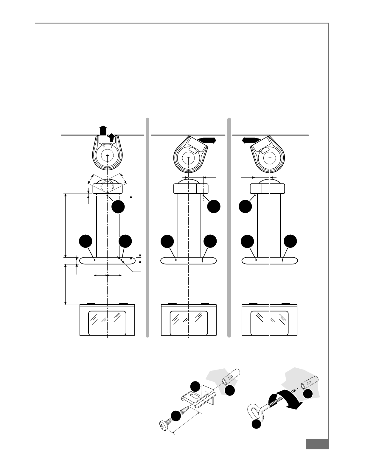
1 - Drilling the shel es:
a) Using the cardboard template
pro ided, and taking hole “B” as
a point of reference, drill the
shel es along the central axis to
allow the passage of the chimney.
The chimney must be inserted into
the shel es before it is fixed to the
hood canopy C (fig. 12).
b)When installing the ducting
ersion with the air outlet directed
upwards, if the ducting fan unit is
positioned below the line of
shel es it will be necessary to drill
a suitable hole in the top shelf only,
to allow the air ducting pipe to pass
through (fig. 13).
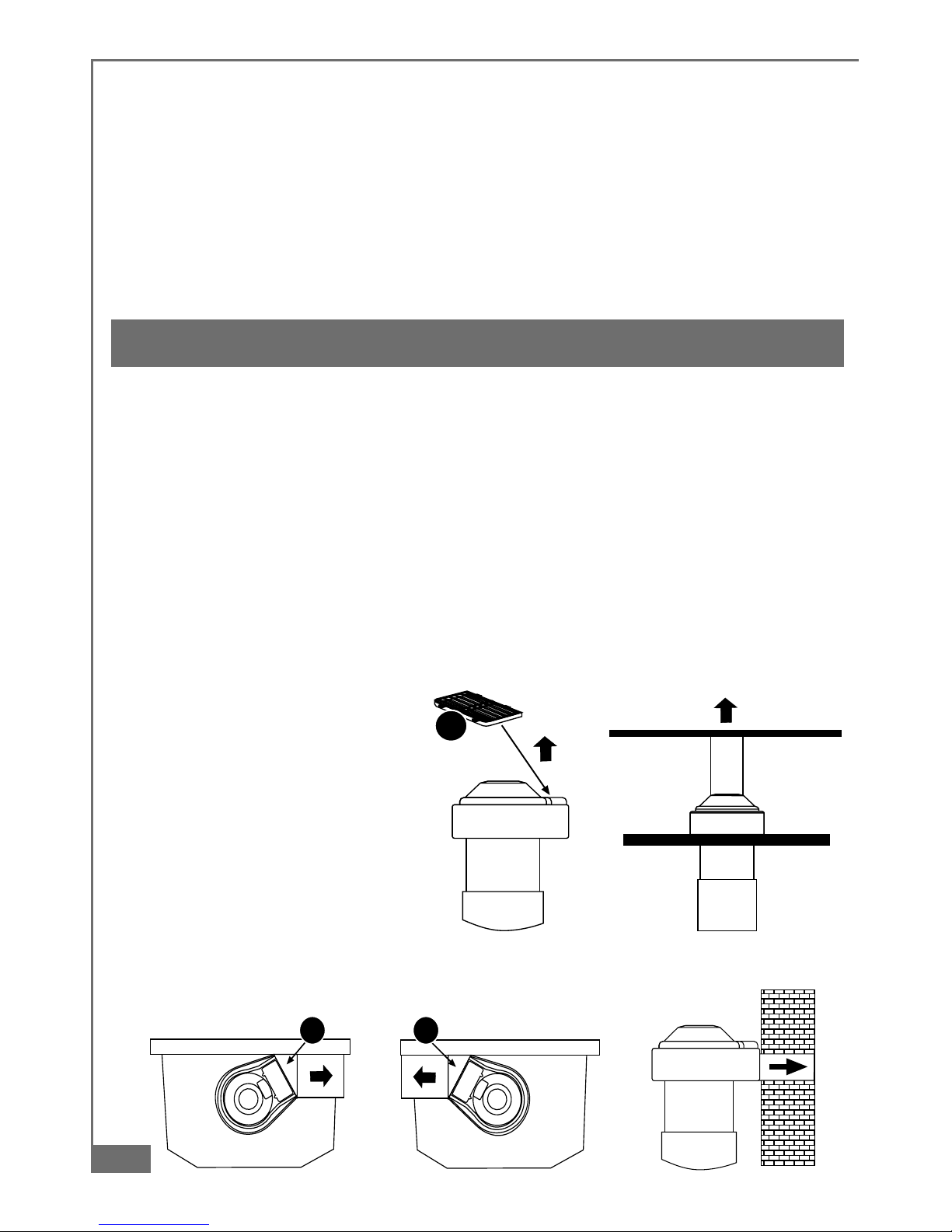
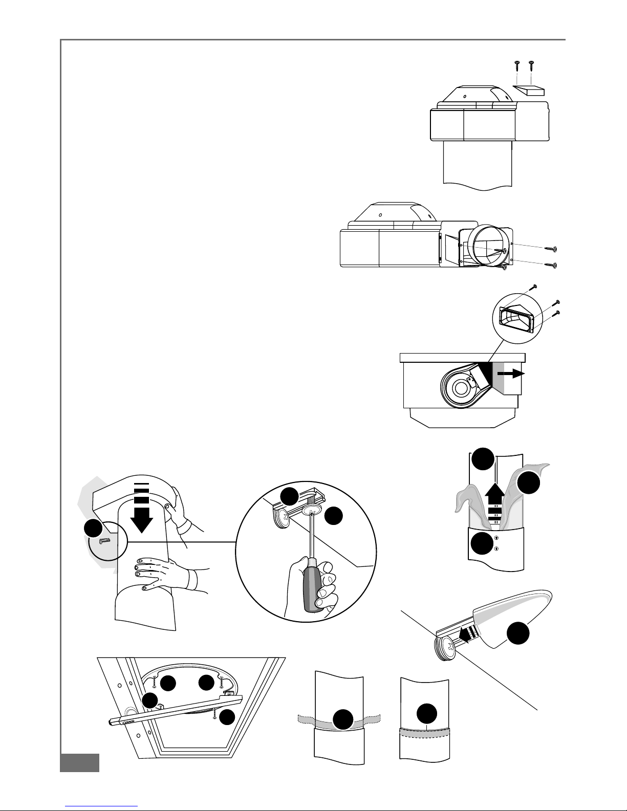
2 - Direction and position of the
ducting fan unit
a) The hood is normally supplied with
the air outlet directed towards the
wall (fig. 3), if it is to be installed with the air outlet directed
to the right or left (fig. 4a-b), it will be necessary to change
the direction of the ducting fan unit, proceeding as follows:
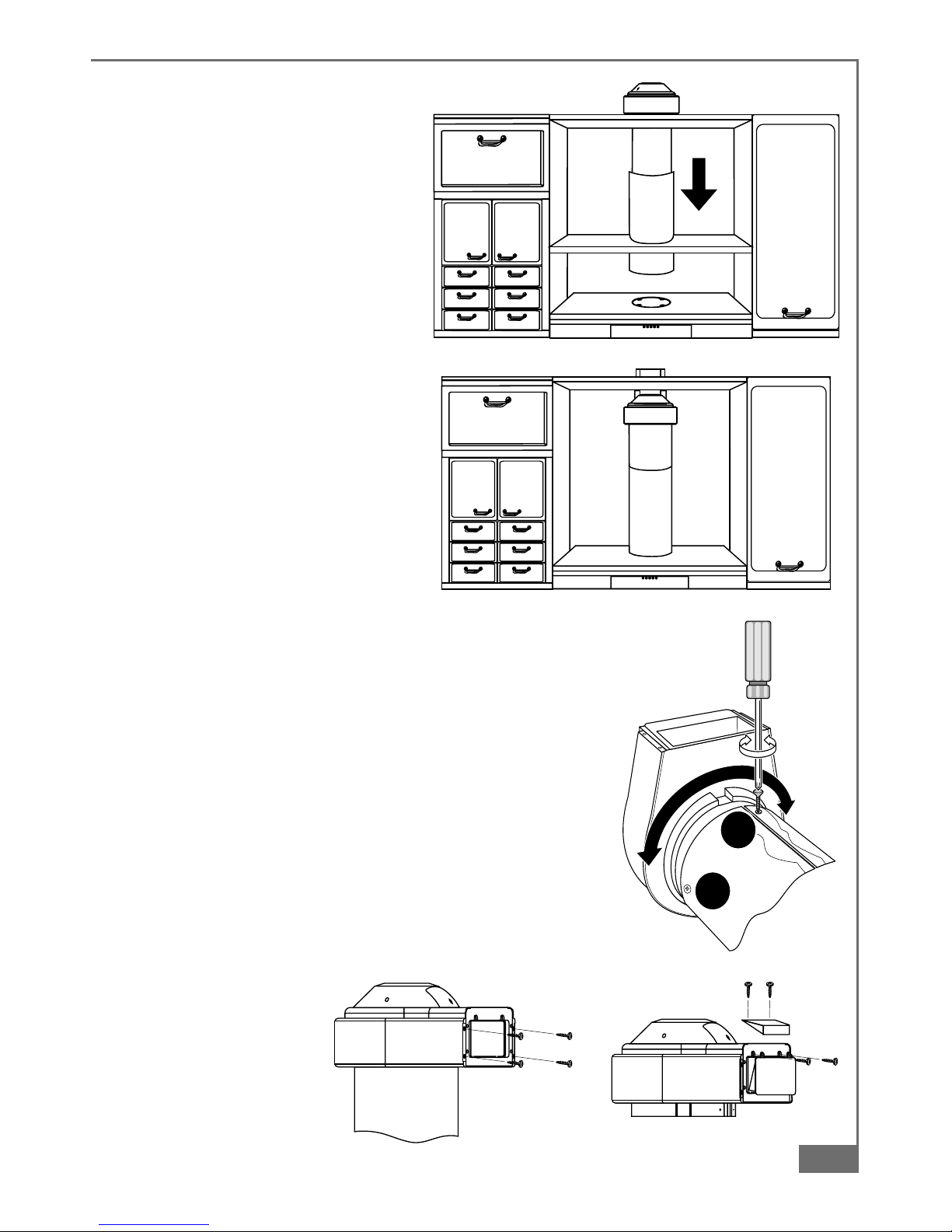
- Unscrew the screws U (fig. 14);
- Turn the ducting fan unit 60° to the right or left;
- Replace the screws U.
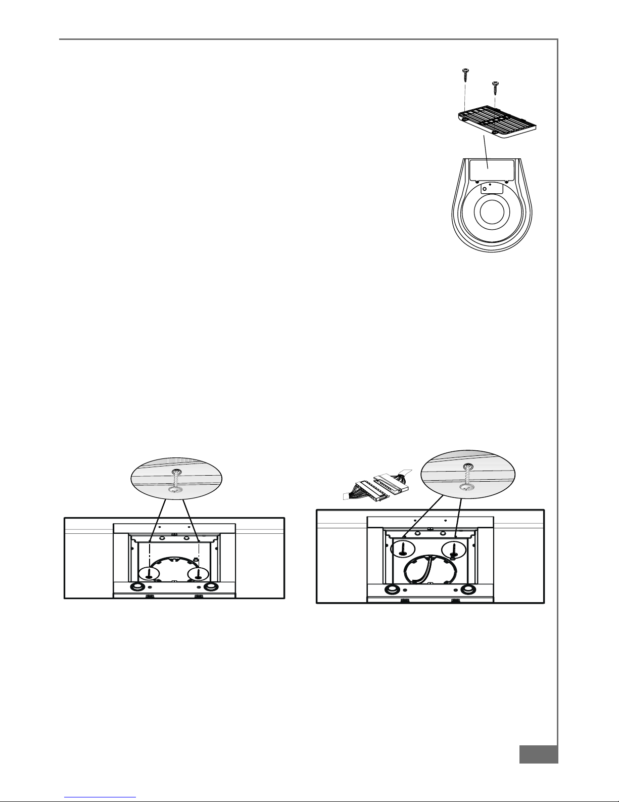
b) The ducting fan unit air outlets must be arranged
according to the type of installation to be carried out.
· Air outlet directed upwards (fig. 2a-b).
- Remo e the plastic plug from the upper part of the enting
grill and replace it on the rear part (fig. 15).
· Air outlet directed towards the wall (fig. 3).
- Remo e the plastic frame from the air outlet (fig. 16).
S36_13
13
S36_12
12
S07_22
15
S07_14
16
U
U
A08_14
14

18
Part 1 - INSTALLATION INSTRUCTIONS
- Remo e the plug from the upper part of the ducting fan unit
(fig. 17), as it is not possible to insert the flange F with the
plug in place.
- Fit the flange F Ø120 or 150 mm (fig. 18), replace the plug.
· Air outlet directed to the right or left hand side (fig. 4a-b).
- Remo e the four screws fastening the plastic frame, as shown
in fig. 16.
- Fit the ducting spigot R (fig. 19) and replace the four screws
remo ed as abo e.
3 - Fixing the chimney
a) Loosen the screws M fixing the two parts
of the chimney and pull the inner section I
(fig. 20) almost all the way out. Remo e
the protecti e film P.
b) Rest the lower section of the chimney in its housing on
the top of the hood canopy. Lower the ducting fan unit
until it reaches the wall bracket S and fix it using the
screw H pro ided (fig. 21). Fit the co er D (pro ided)
on the wall bracket S (fig. 22).
c) Fix the chimney A to the hood canopy C using the four
screws pro ided (fig. 23).
d) Insert the transparent seal Q (pro ided), so as to elimi-
nate any play between the two parts of the chimney
(fig. 24). Lock the screws M.
e) Remo e the support rod B.
17
S07_16
18
R
S07_19
19
I
P
M
A08_20
20
S
S
H
A08_21
21
D
A08_22
22
EE
E
E
A08_23
23
Q
A08_24
Q
24

19
Part 1 - INSTALLATION INSTRUCTIONS
4.4 - Ducting or recirculation fitting
1 - Ducting fitting.
This is possible for all forms of installation:
a) Connect the air outlet to the external ducting system.
b) Remo e the acti ated charcoal filter (if there is one) inside the
hood canopy (see Maintenance).
2 - Recirculation fitting
This is only possible with the air outlet directed upwards. Fit the
enting grille G onto the air outlet (Fig. 25). The acti ated charcoal
filter should be fitted inside the hood canopy after connection to
the power supply.
4.5 - Connection to power supply and checking of good
working order
1 - It is absolutely necessary to follow the warnings 3.2, 3.3 and 3.4 of paragraph 3,
concerning safety measures.
2 - Loosen the two locking screws and remo e the metal co er (fig.26).
Connect the hood connection to the engine connection (fig.27a). Correctly place the
connectors under the co er and tighten the two locking screws (fig. 27b).
3 - Once electrical connection has been carried out, check that lights, engine and change
of speed work
4 - Fit the lower grill and the acti ated carbon filter (only for filter mode) (see Maintenance).
27b S36_27
27a
S07_23
25
S36_26
26

20
Part 2 - USE AND MAINTENANCE INSTRUCTIONS
1 - SAFETY WARNINGS
It is most important that all the warnings shown in paragraph 3 of the Installation
Instru tions are stri tly observed. Moreover, pay spe ial attention to the following
warnings during the use and maintenan e of the ooker hood:
1.1 - The grease filters and har oal filters should be leaned or repla ed as re ommended
by the manufa turer or more frequently if the hood is used onsistently (over 4 hours
per day).
1.2 - When using a gas hob in onne tion with the ooker hood never leave the burners of
the hob un overed while the hood is in use or when the pans have been removed.
Swit h off the gas before removing the pan, or for just short periods and never leave
the hob unattended.
1.3 - Always ensure that the flame is kept at the orre t intensity to prevent the flame
from li king round from the bottom of the pan; this will save energy and will avoid a
dangerous on entration of heat.
1.4 - Always ensure that the applian e is used in a ordan e with the manufa turer’s
instru tions for the removal of ontaminated air and odours during ooking.
2 - OPERATION
Control panel (fig. 28)
The cooker hood can be operated as follows:
BUTTON L= Turns the lighting
system on and
off;
BUTTON V1 =
Turns the on and
off at low speed.
This is ideal to
obtain a particularly silent but continuous flow of air when the le el of
cooking fumes is low;
BUTTON V2 = Medium speed, suitable for most normal operating conditions. This
gi es an excellent ratio between treated air flow and noise le el;
BUTTON V3 = High speed, suitable to deal with hea y cooking fumes, e en for long
periods of time.
3 - MAINTENANCE
Constant maintenance is a guarantee for long-lasting working order and efficiency.
Special care should be taken of the metal antigrease filter and acti ated carbon filter
(for filter hoods only).
28
S36_28
V1 V2 V3 L

21
Part 2 - USE AND MAINTENANCE INSTRUCTIONS
S36_29
29
S36_30
G1G1
30
S36_31
31
3.1 - Metal antigrease filters
1 - Cleaning
It is necessary to wash these filters at least
e ery two months with a normal detergent;
their compact size enables them to be
washed also in dishwasher.
2 - Replacement
Remo e the metal grease filter by remo ing
the filter retaining clips (fig. 29).
3.2 - Acti ated carbon filters
1 - How they work
The acti ated carbon filter can hold odours until
it reaches total saturation. It is not washable
nor can it be re-used, but should be changed
at least e ery 4 months or more often in case
of intensi e use.
2 - Replacement
Remo e the antigrease filters and the acti ated
carbon filter from its seat by acting on the
hooks G1 (fig. 30). Fit the new acti ated
carbon filter and the metal antigrease filters.
WARNING: Maintenan e or repla ement
periods should be respe ted to avoid any
fire hazards when the filters get saturated
with grease.
3.3 - Light
1 - It consists of 2 20 W-halogen spotlights.
2 - Replacement (fig. 31)
Remo e the two screws that lock the metal ring, take the spotlight out of its holder by
pulling slightly. When replacing, make sure that both pins are well inserted in the
holder seat.
3.4 - Cleaning
Normal cleaning operation of the hood:
- Do not use any wet cloth or sponge or water-jet.
- Do not use diluents or alcohol, as they could make the painted surfaces opaque.
- Do not use abrasi e products, especially on stainless steel surfaces.
We re ommend the use of a damp loth and any neutral liquid detergent.

22

23

4329410_02 - 040122