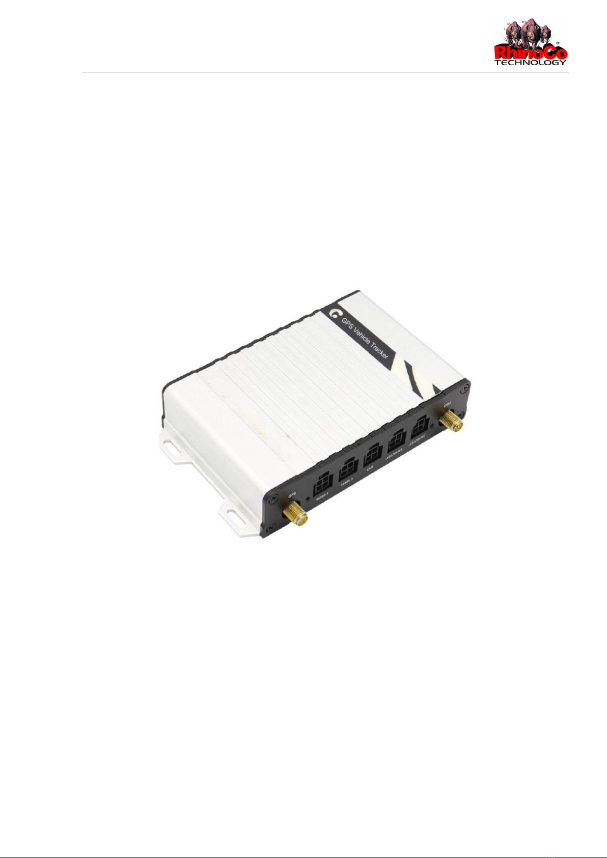
Rhinotracks ST-5 User Guide
Digital input 2 (negative trigger)
Connect to a door trigger signal cable to detect vehicle door status.
(Most Chinese, Korean, and Japanese cars are negative
edge-triggered). The port can be set to positive trigger, AD input 3 (0–30 V), or
output 5.
Output 3
Valid: low level (0 V)
Invalid: open collector
Maximum voltage for output open collector (invalid): 40 V
Maximum current for output low voltage (valid): 500 mA
Connect to an external relay to remotely cut off the vehicle fuel cable or engine
power supply. The port can be set to positive or negative input 6.
Digital input 3 (positive trigger)
Connect to the vehicle ACC cable by default to detect the vehicle
ACC status. The port can be set to negative trigger, AD input 6 (0–30 V), output
6.
Analog input 1 with 12-bit resolution and valid voltage 0–30 V
Connect to an external sensor, such as the fuel level sensor.
The port can be set to positive or negative input 4 or output 7.
Analog input 2 with 12-bit resolution and valid voltage 0–30 V
There is a white plug on the AD cable, and the cable is connected
to the A53 fuel level sensor by default.
The port can be set to positive or negative input 5 or output 8.
Output 1
Valid: low level (0 V)
Invalid: open collector
Maximum voltage for output open collector (invalid): 40 V
Maximum current for output low voltage (valid): 400 mA
Connect to an external relay to remotely cut off the vehicle fuel
cable or engine power supply.
The port can be set to positive or negative input 7.
Output 2
Valid: low level (0 V)
Invalid: open collector
Maximum voltage for output open collector (invalid): 40 V
Maximum current for output low voltage (valid): 400 mA
Connect to a buzzer.
The port can be set to positive or negative input 8.
12 (1-wire, Digital
temperature
sensor or iButton
input port)
TTL3.3V level
Connect to the A52 digital temperature sensor or iButton by
default by using the A61 sensor box.
The port can be set to negative input 9 or output 4.
Note: The DC or AC voltage that is greater than 3.3 V is not
allowed. Otherwise, the device may be damaged.