Rittal 4055.040 User manual

Elektro-Hydraulikstanze
Electric hydraulic punch
4055.040
Montage- und Bedienungsanleitung
Assembly and operating instructions


1 Hinweise zur Dokumentation
Montage-, Installations- und Bedienungsanleitung Elektro-Hydraulikstanze mit Akku 3
DE
Inhaltsverzeichnis
1 Hinweise zur Dokumentation . . . . . . .
1.1 Mitgeltende Unterlagen. . . . . . . . . . . . . . . . 3
1.2 CE-Kennzeichnung . . . . . . . . . . . . . . . . . . . 3
1.3 Aufbewahrung der Unterlagen . . . . . . . . . . 3
1.4 Verwendete Symbole. . . . . . . . . . . . . . . . . . 3
2 Sicherheitshinweise. . . . . . . . . . . . . . 4
3 Bestimmungsgemäße Verwendung . 4
4 Leistungsdaten. . . . . . . . . . . . . . . . . . 4
5 Beschreibung . . . . . . . . . . . . . . . . . . . 5
6 Betätigungsfunktion . . . . . . . . . . . . . 5
7 Stanzen mit Rund-, Quadrat- und
Rechtecklocher . . . . . . . . . . . . . . . . . 6
8 Verfügbare Zugbolzen,
Distanzeinsätze und
Distanzbuchsen . . . . . . . . . . . . . . . . . 7
9 Betriebsdauer. . . . . . . . . . . . . . . . . . . 7
10 Technische Daten
Akku und Ladegerät . . . . . . . . . . . . . 8
11 Akku und Ladegerät . . . . . . . . . . . . . 8
12 Stanzzeit und Stanzleistung . . . . . . . 9
13 Wartung . . . . . . . . . . . . . . . . . . . . . . . 9
14 Aufbewahrung und Transport. . . . . . 9
15 Entsorgung . . . . . . . . . . . . . . . . . . . . . 9
16 EG-Konformitätserklärung . . . . . . . 10
1 Hinweise zur Dokumentation
Vor Inbetriebnahme lesen und aufbewahren!
1.1 Mitgeltende Unterlagen
Für die hier beschriebenen Gerätetypen existiert eine
Montage-, Installations- und Bedienungsanleitung als
Papierdokument dem Gerät beiliegend.
Für Schäden, die durch Nichtbeachtung dieser Anlei-
tungen entstehen, übernehmen wir keine Haftung. Ge-
gebenenfalls gelten auch die Anleitungen des verwen-
deten Zubehörs.
1.2 CE-Kennzeichnung
Die Konformitätserklärung liegt dem Gerät als separa-
tes Dokument bei.
1.3 Aufbewahrung der Unterlagen
Diese Anleitung sowie alle mitgeltenden Unterlagen
sind Teil des Produktes. Sie müssen dem Anlagenbe-
treiber ausgehändigt werden. Dieser übernimmt die
Aufbewahrung, damit die Unterlagen im Bedarfsfall zur
Verfügung stehen.
1.4 Verwendete Symbole
Ein Blickfangpunkt zeigt an,
dass eine Handlung
durchzuführen ist.
Gefahr!
Unmittelbare Gefahr für Leib und Leben!
Achtung!
Mögliche Gefahr für Produkt
und Umwelt.
Hinweis:
Nützliche Informationen
und Besonderheiten.

4 Montage-, Installations- und Bedienungsanleitung Elektro-Hydraulikstanze mit Akku
2 Sicherheitshinweise
DE
2 Sicherheitshinweise 3 Bestimmungsgemäße
Verwendung
Die Elektro-Hydraulikstanze mit Akku ist bestimmt zum
Stanzen von Blechen.
4 Leistungsdaten
Tab. 1: Leistungsdaten
Die optimale Betriebstemperatur für das Akku-Hand-
hydraulik-Gerät liegt zwischen 15° und 25°
Achtung!
– Beim Bohren des Führungslochs sowie
beim Stanzen Schutzbrille tragen.
– Während des Stanzvorgangs nicht mit den
Händen in den Stanzbereich eingreifen, da
dies zu Quetschungen und Verletzungen
führen kann.
– Stellen Sie sicher, dass sich während des
Stanzens keine Personen vor oder in un-
mittelbarer Nähe des Stempels aufhalten,
da diese im Fall eines Materialversagens
oder Falscheinsatzes durch Splitter verletzt
werden könnten.
– Vor Auswechslung der Stanzeinsätze un-
bedingt Akkupaket gegen unbeabsichtig-
tes Betätigen aus dem Gerät entfernen.
– Beim Betrieb kann es zur Funkenbildung
kommen, durch die feuergefährliche oder
explosive Stoffe in Brand gesetzt werden
können.
– Bei intensivem Gebrauch kann es durch
Überhitzung zu Schäden am Gerät kom-
men. Das Stanzgerät darf nicht in Feucht-
räumen eingesetzt werden.
– Der Stanzvorgang kann jederzeit durch
Loslassen des Bedienschalters unterbro-
chen werden dann kann das Gerät durch
Drücken des Rückstellhebels entlüftet
werden.
Rundlocher bis 80 mm Ø
(3,0 mm St. 37; 2,0 mm Chromnickelstahl)
Formlocher
68 x 68 mm
(3,0 mm St. 37; 2,0 mm Chromnickelstahl)
92 x 92 mm nur mit Sonderzugschraube
und Distanzbuchse (2,0 mm St. 37; 1,5 mm
Chromnickelstahl)
Stanzkraft 80 kN mit Überdruckventil
5 Beschreibung
Montage-, Installations- und Bedienungsanleitung Elektro-Hydraulikstanze mit Akku 5
DE
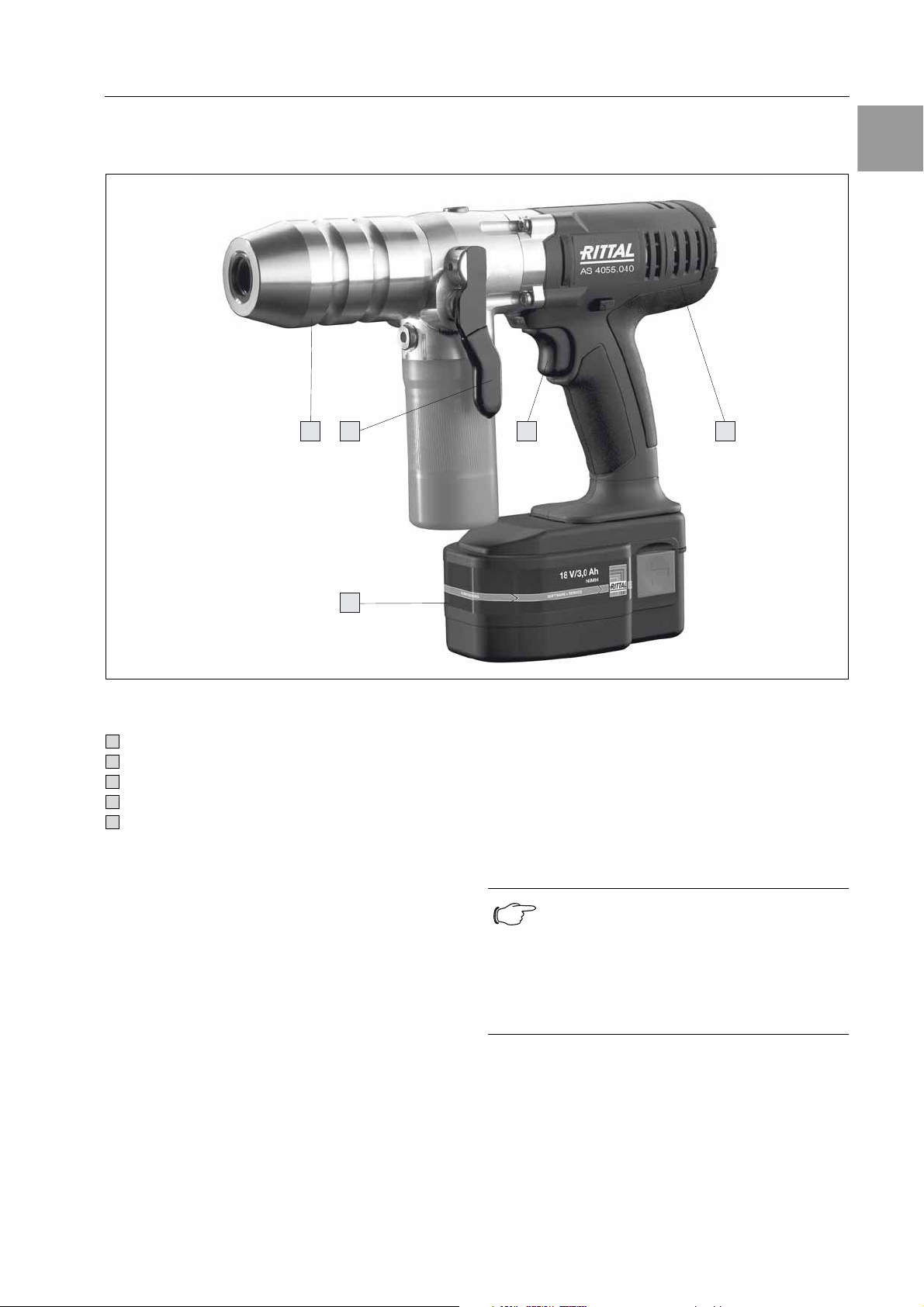
5 Beschreibung
Die Elektro-Hydraulikstanze ist ein handgeführtes Ge-
rät und besteht aus folgenden Komponenten:
Abb. 1: Elektro-Hydraulikstanze
Legende
6 Betätigungsfunktionen
Der Stanzvorgang wird durch Betätigung des Bedien-
schalters ausgelöst. Dieser Schalter muss während
des Stanzvorgangs kontinuierlich gedrückt werden.
Nach Beendigung des Stanzvorgangs (wenn der
Stempel das Material vollständig durchgestanzt hat)
muss der Schalter freigeben werden. Durch einmaliges
Drücken des Rückstellhebels fährt der Kolben mit der
Zugachse wieder in seine Ausgangsposition zurück.
3 21 4
5
Stanzkopf Kopf zur Aufnahme des Zugbolzens einschl. Stempel und Matrize
Bedienschalter Auslösung des Stanzvorgangs
Rückstellhebel Hebel zur Entlüftung des Stanzkopfes
Antrieb Antrieb mit Bedienschalter
Akku Wiederaufladbarer 18 V, 3,0 Ah NiMH Akku
1
2
3
4
5
Hinweis:
Sollte das Gerät bis zur maximalen Druck-
grenze beansprucht werden
(infolge falscher Werkzeugauswahl,
falscher Distanzbuchsen oder falscher
Zusammenstellung), ist ein höherer Druck
auf den Rückstellhebel erforderlich.
6 Montage-, Installations- und Bedienungsanleitung Elektro-Hydraulikstanze mit Akku
7 Stanzen mit Rund-, Quadrat- und Rechtecklocher
DE
7 Stanzen mit Rund-, Quadrat- und
Rechtecklocher
1. Vorbohren mit Spiralbohrer oder Mehrstufen-
bohrer.
Bohrdurchmesser bei Standardblechlochern:
bei Schrauben Ø 9,5 mm min. Ø 11,0 mm
bei Spaltstempeln Ø 10,0 mm
bei Schrauben Ø 11,1 mm für rostfreies Material
min. Ø 11,5 mm
bei Schrauben Ø 19,0 mm min. Ø 20,4 mm
(Kleineren Durchmesser vorbohren und dann lochen
ist auch möglich).
Abb. 2: Bohrlochdurchmesser
2. Hydraulikschraube mit der kurzen Gewindeseite
Ø 19,0 mm ganz in den Hydraulikzylinder ein-
schrauben.
3. Passende Distanzbuchse mit der Matrize auf die
Hydraulikschraube setzen.
4. Hydraulikschraube durch das vorgebohrte Loch
schieben und Rundstempel von der Rückseite auf-
schrauben. Bei Quadrat- und Rechtecklochern
Stempel auf die Achsführung stecken und mit der
jeweiligen Kontermutter sichern. Bei der Montage
der Hydraulikschraube für Quadrat- und Rechteck-
locher darf ausschließlich die lange Gewindeseite
in den Stanzkopf eingeschraubt werden.
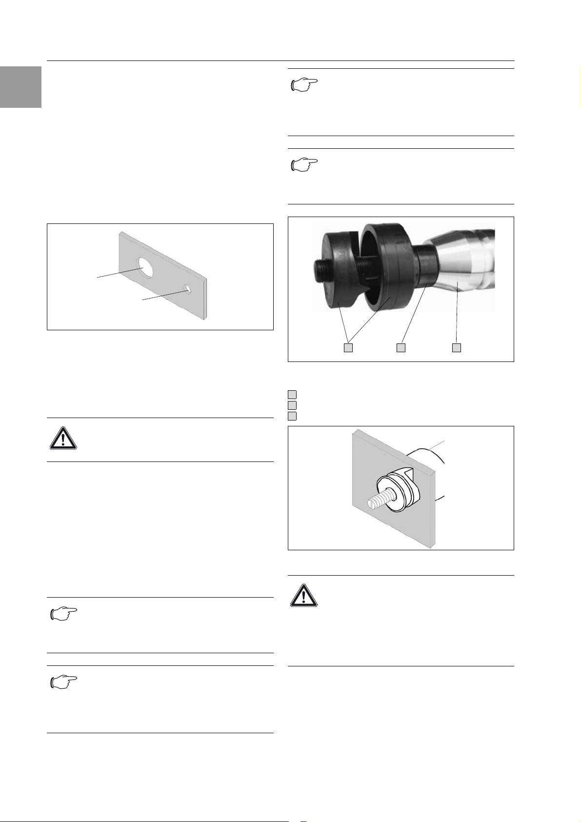
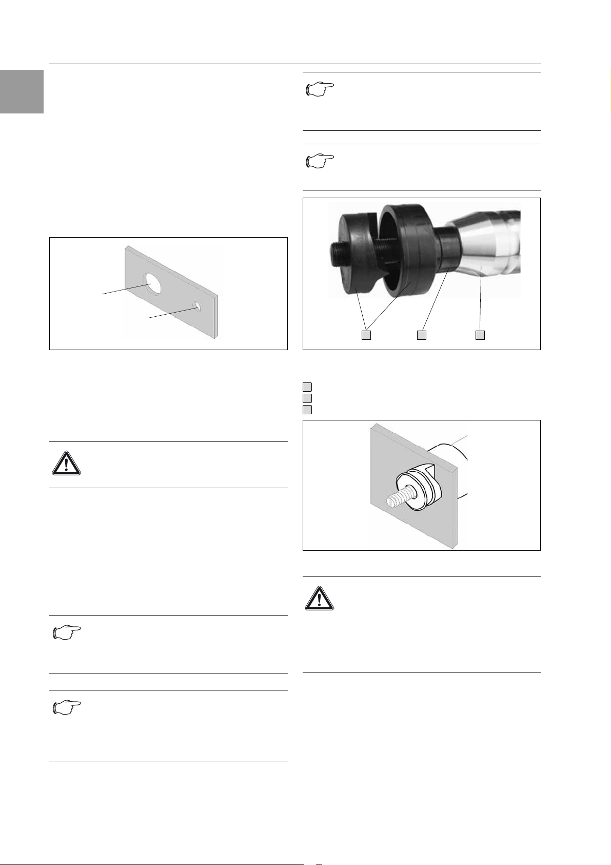
Die Matrize an der angebrachten Fadenkreuz-
markierung mittels der Strichmarkierung am
Stempel ausrichten.
Abb. 3: Anordnung Stempel und Matrize
Legende
Stanzkopf
Stanzeinsätze (Stempel und Matrize)
Distanzbuchsen
Abb. 4: Bearbeitungszustand – Ansicht Stempel
Achtung!
Der Einsatz einer Distanzbuchse ist
unbedingt erforderlich.
Hinweis:
Achten Sie auf die richtige Stempel- und
Matrizen-Kombination. Der Durchmesser
ist jeweils aufgeprägt.
Hinweis:
Nicht mit unvollständig aufgeschraubten
Stempeln lochen. Die ganzen Gewinde-
gänge des Stempels müssen auf der Zug-
schraube aufgeschraubt sein.
Ø 20,4 mm
Ø 10,0 mm
Ø 11,0 mm
Ø 11,5 mm
Hinweis:
Der Stempel darf nicht innen in der Matrize
aufsitzen. Dies kann zu Beschädigungen
am Werkzeug und an der Hydraulikstanze
kommen.
Hinweis:
Der Stempel muss so aufgeschraubt wer-
den, dass er schon leichten Kontakt mit
dem Blech hat.
Achtung!
Bei Einsatz von Quadratlochern
92 x 92 mm sind die Sonderzugachse
und die Distanzbuchse notwendig. Die
Distanzbuchse fest auf die Matrize des
Quadratlochers 92 x 92 mm schrauben.
Auf Anfrage.
1
2
3
1
2
3
8 Zugschrauben, Distanzeinsätze, Distanzbuchsen
Montage-, Installations- und Bedienungsanleitung Elektro-Hydraulikstanze mit Akku 7
DE
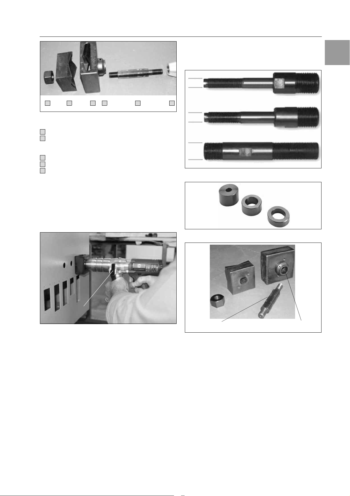
Abb. 5: Anordnung Stempel, Matrize für Quadratlocher
Legende
Stanzkopf
Stanzeinsatz:
Stempel 92 x 92 mm,
Matrize 92 x 92 mm
Distanzbuchse
Kontermutter
Sonderzugachse
5. Betätigen Sie den Bedienschalter und der Stanz-
vorgang wird eingeleitet. Sobald der Stempel
durch das Blech bricht, ist der Stanzvorgang
beendet.
6. Drücken Sie den seitlichen Rückstellhebel damit
die Stanze entlüftet wird und der Kolben in die
Ausgangsstellung zurück fährt.
Abb. 6: Funktion Rückstellhebel
7. Schrauben Sie den Stempel ab bzw. lösen Sie die
Kontermutter. Entfernen Sie den Stanzabfall aus
der Matrize.
8 Verfügbare Zugschrauben,
Distanzeinsätze und Distanz-
buchsen
Abb. 7: Verfügbare Zugschrauben
Abb. 8: Distanzeinsätze
Abb. 9: Sonderzugachse, Distanzbuchse, auf Anfrage
9 Betriebsdauer
Das Gerät ist nicht für den Dauerbetrieb geeignet.
Nach ca. 40 bis 50 Stanzvorgängen sollte eine Pause
von 10 bis 20 Minuten eingelegt werden, damit das
Gerät abkühlt.
8
7
1
6
6
9
1
6
7
8
9
Rückstellhebel
Best.-Nr. 4055.661
Best.-Nr. 4055.662
Best.-Nr. 4055.663
9,5 mm
11,1 mm
19 mm
Sonderzugachse Distanzbuchse

8 Montage-, Installations- und Bedienungsanleitung Elektro-Hydraulikstanze mit Akku
10 Technische Daten Akku und Ladegerät
DE
10 Technische Daten
Akku und Ladegerät
Tab. 2: Technische Daten Akku und Ladegerät
11 Akku und Ladegerät
Abb. 10: Akkumontage von vorne
Abb. 11: Akkumontage von hinten
Der Akku kann, für optimalen Gewichtsausgleich zum
eingesetzten Stanzwerkzeug, beidseitig verwendet
werden.
Das Ladegerät ist für eine Spannung von 230 Volt/
50 HZ ausgelegt.
Abb. 12: Akku
Abb. 13: Ladegerät
Neue Akkus müssen vor dem erstmaligen Gebrauch
vollständig geladen werden. Zur Aufladung des Akkus
den Stecker des Ladegerätes in die Steckdose stek-
ken und den Akku in das Ladegerät einsetzen. Die
Ladezeit beträgt ca. 45 min.
Der Ladezustand des Akkus kann an einer Leuchtdi-
ode am Ladegerät abgelesen werden.
Grün: Akku ist vollständig aufgeladen
Rot: Akku ist leer und wird geladen
Blinken: Akku ist nicht vollständig eingeschoben
oder Akku zu heiß. Ein akustisches Signal
ertönt.
Akku 18 V, 3,0 Ah NiMH
Ladezeit 45 min. nach Vollentladung
Ladezyklen ~ 500 bei Normalbedingungen
Einsatz 0°C…+ 40°C, Kapazitätsverlust unter 0°C
Ladegerät – lädt alle Akkus 18 - 28 V, kompatibel für
NiCD-, NiMH- und Li-Ionen-Akkus.
– autom. Temperaturüberwachung.
– der Wechsel von Schnellladung auf
Erhaltungsladung verhindert Überladung
der Akku-Zellen.
– der Ladezustand wird durch die LED-
Anzeige angezeigt.
– die Platine ist komplett vergossen.
Achtung!
Es dürfen keine artfremden Akkus im
Ladegerät verwendet werden.
Hinweis:
Akku und Ladegerät vor Feuchtigkeit
schützen.
Achtung!
Nicht mit schwachen oder teilentladenen
Akkus, besonders beim Einsatz größerer
Durchmesser, Quadrat- und Rechteck-
locher arbeiten. Das Gerät kann mitten
im Stanzvorgang stehen bleiben und es
kann zu Beschädigungen kommen.
Hinweis:
Laden Sie den Akku auf, sobald die
Geschwindigkeit der Hydraulikstanze
merklich nachlässt.
Hinweis:
Laden Sie einen teilentladenen Akku nicht
nach.
Hinweis:
Möchten Sie zwei Akkus hintereinander auf-
laden, warten Sie ca. 15 Minuten, bevor Sie
den zweiten Akku nachladen.
12 Stanzzeit und Stanzleistung
Montage-, Installations- und Bedienungsanleitung Elektro-Hydraulikstanze mit Akku 9
DE
12 Stanzzeit und Stanzleistung
Tab. 3: Stanzzeit und Stanzleistung
13 Wartung
Das Gerät ist prinzipiell wartungsfrei.
Baut das Gerät keinen Druck mehr auf oder verliert Öl,
kontaktieren Sie den Lieferanten oder den Kunden-
dienst.
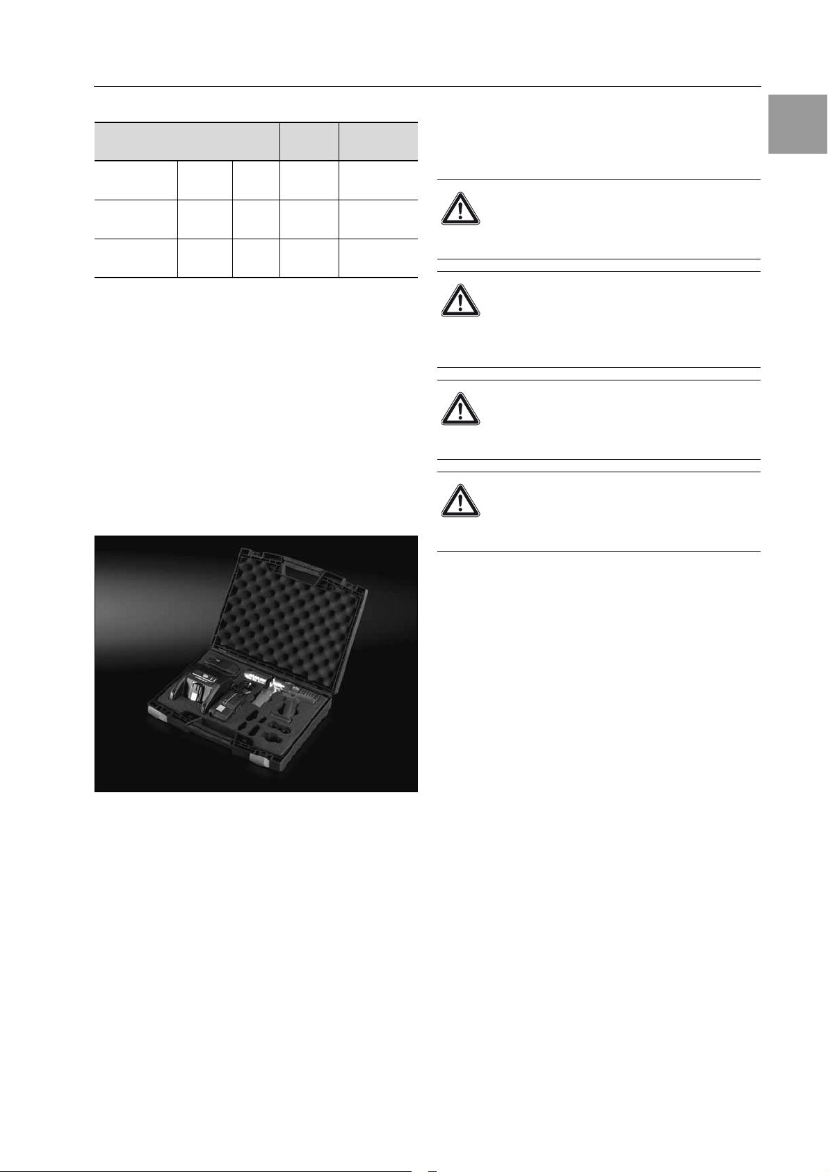
14 Aufbewahrung und Transport
Das Stanzgerät nach Gebrauch im Transportkoffer
lagern. Das Stanzgerät trocken lagern.
Abb. 14: Transportkoffer
15 Entsorgung
Die Entsorgung der einzelnen Komponenten muss ge-
trennt erfolgen. Das Öl muss zuerst abgelassen und
entsorgt werden.
Stanz-
zeit
Stanz-
leistung
22,5 mm Ø St. 37 2 mm 5 sec. 190 Löcher/
Akku
63,5 mm Ø St. 37 2 mm 7 sec. 100 Löcher/
Akku
68 x 68 mm St. 37 2 mm 7 sec. 70 Löcher/
Akku
Achtung!
Bei der Entsorgung aller Teile der
Hydraulikstanze beachten Sie bitte die
EG-Umwelt-Standards.
Achtung!
Hydrauliköle stellen eine Gefahr für das
Grundwasser dar. Unkontrolliertes Ab-
lassen oder unsachgemäßes Entsorgen
ist verboten.
Achtung!
Der Akku muss speziell unter Berück-
sichtigung der Batterieverordnung ent-
sorgt werden.
Achtung!
Das Gerät darf nicht als Einheit im Rest-
müll entsorgt werden, da es Umwelt-
schäden verursachen kann.

10 Montage-, Installations- und Bedienungsanleitung Elektro-Hydraulikstanze mit Akku
16 EG-Konformitätserklärung
DE
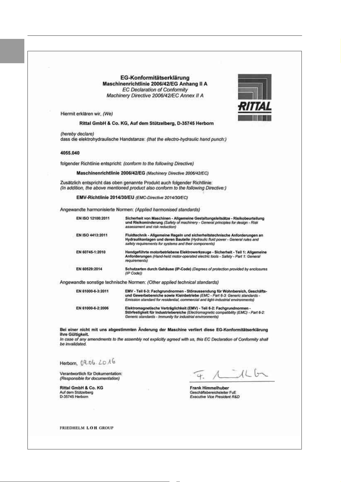
16 EG-Konformitätserklärung

1 Notes on documentation
Electric hydraulic punch assembly instructions 11
EN
Contents
1 Notes on documentation. . . . . . . . . . .
1.1 Associated documents . . . . . . . . . . . . . . . 11
1.2 CE labelling. . . . . . . . . . . . . . . . . . . . . . . . . 11
1.3 Retention of documents . . . . . . . . . . . . . . 11
1.4 Symbols used . . . . . . . . . . . . . . . . . . . . . . . 11
2 Safety instructions. . . . . . . . . . . . . . 12
3 Specified Conditions of Use . . . . . . 12
4 Performance dates . . . . . . . . . . . . . 12
5 Description . . . . . . . . . . . . . . . . . . . . 13
6 Operating functions . . . . . . . . . . . . . 13
7 Punching with round, square
and oblong puncher. . . . . . . . . . . . . 14
8 Available hydraulic screws,
distance inserts and
spacer sleeves . . . . . . . . . . . . . . . . . 15
9 Operating time . . . . . . . . . . . . . . . . . 15
10 Technical data battery and
battery charger. . . . . . . . . . . . . . . . . 16
11 Battery and battery charger . . . . . . 16
12 Punching time and punching
capacity . . . . . . . . . . . . . . . . . . . . . . 17
13 Maintenance
14 Storage and transport . . . . . . . . . . . 17
15 Disposal . . . . . . . . . . . . . . . . . . . . . . 17
16 CE-Declaration of Conformity . . . . 18
1 Notes on documentation
Please read and save these instructions!
1.1 Associated documents
Assembly and operating instructions exist as paper
documents for the unit types described here and are
enclosed with the equipment.
We cannot accept any liability for damage associated
with failure to observe these instructions. Where appli-
cable, the instructions for any accessories used also
apply.
1.2 CE labelling
The declaration of conformity is supplied with the unit
as a separate document.
1.3 Retention of documents
These instructions and all associated documents con-
stitute an integral part of the product. They must be
given to the plant operator. The operator is responsible
for storage of the documents so they are readily avail-
able when needed.
1.4 Symbols used
The bullet point indicates
an action to be performed.
Danger!
Immediate danger to life and limb!
Caution!
Potential threat to the product
and the environment.
Note:
Useful information
and special features.
12 Electric hydraulic punch assembly instructions
2 Safety instructions
EN
2 Safety instructions 3 Specified conditions of use
The Battery Packed Compact Hydraulic Punch is des-
tined to punch metal sheets.
4 Performance dates
Tab. 1: Performance dates
The optimal working temperature for the Battery
Packed Compact Hydraulic Punch is between 15° and
25°C.
Danger!
– Wear safety goggles during drilling the
guiding hole and during punching.
– Keep hands out of the punching area
during the punching process to avoid
serious injuries.
– Make sure that no other persons stay in
front or close to the hydraulic punch during
the punching process to avoid serious in-
juries caused by splinters at material failure
or incorrect use of hydraulic punch.
– Before changing the punching inserts it’s
absolutely necessary to remove the battery
from the device to avoid unintended use.
– While operating it can come to sparking
which could set fire on flammable or
explosive materials.
– At intensive operating the hydraulic punch
can be damaged because of overheating.
– The hydraulic punch must not be operated
in damp locations.
– The punching process can be interrupted
at any time by releasing the operating
switch. Then the hydraulic punch can be
vented by pressing the vent lever.
Round punch up to 80 mm Ø
(3.0 mm St. 37, 2.0 mm chrome nickel steel)
Square and
oblong
punches
68 x 68 mm
(3.0 mm St. 37, 2.0 mm chrome nickel steel)
92 x 92 mm only with special hydraulic
screw and spacer sleeves
(2.0 mm St. 37, 1.5 mm chrome nickel steel)
Punching
capacity 880 kN with pressure relief valve

5 Description
Electric hydraulic punch assembly instructions 13
EN
5 Description
The Electric hydraulic punch is a hand operated device
and is made up of the following components:
Fig. 1: Electric hydraulic punch
Key
6 Operating functions
The punching will be initiated through the activation of
the operating switch. This switch must be pressed dur-
ing the whole punching process. After terminating of
the punching process (if the punch has perforated
completely) unblock the switch. By pressing the vent
lever once the piston moves backwards to its starting
position.
3 21 4
5
Punching head head for the reception of the tension bolt including punch and die
Operating switch initiating of the punching procedure
Vent lever lever for vent of the punching head
Drive drive with operating switch
Battery rechargeable 18 V, 3.0 Ah NiMH battery
1
2
3
4
5
Note:
If the hydraulic punch is strained to the
maximum pressure limit (due to improper
tool selection, incorrest spacers or false
assembly) a higher pressure to the vent
lever is necessary.
14 Electric hydraulic punch assembly instructions
7 Punching with round, square and oblong puncher
EN
7 Punching with round, square and
oblong puncher
1. Pre-drilling with a twist drill or a multistep drill
Drilling diameter for standard punches:
for screws with Ø 9.5 mm drill min. Ø 11.0 mm
for split punches drill Ø 10.0 mm
for screws with Ø 11.1 mm in stainless material drill
min. Ø 11.5 mm
for screws with Ø 19.0 mm drill min. Ø 20.4 mm
(pre drilling a smaller diameter und then punching is
also possible).
Fig. 2: Borehole diameter
2. Screw the hydraulic screw with the short thread
side Ø 19.0 mm completely into the hydraulic
cylinder.
3. Place the suitable spacer sleeves with the die on
the hydraulic screw.
4. Put the hydraulic screw through the pre drilled hole
and screw in the round punch from the backside.
For square and oblong punches plug the punch on
the axis guidance of the hydraulic screw and retain
with the corresponding counter nut. When mount-
ing the hydraulic screw for square and oblong
punches, screw only the long threaded side into
the punching head. Align the die to the crossline
mark using the line mark on the stamp.
Fig. 3: Positioning punch and die
Key
Punching head
Punching inserts (punch and die)
Spacer sleeve
Fig. 4: Processing status – view punch
Danger!
The application of a spacer sleeve is
absolutely necessary.
Note:
Pay attention on the right combination of
punch and die. The diameter is stamped on
correspondingly.
Note:
Do not punch with incomplete screwed in
punches. The whole thread turns of the
punch have to be screwed in on the
hydraulic screw.
Ø 20.4 mm
Ø 10.0 mm
Ø 11.0 mm
Ø 11.5 mm
Note:
The punch should not hit the interior ground
of the punch. This can cause damages to
the tool and on the hydraulic punching unit.
Note:
The punch must be screwed on, that a
gentle contact with the sheet is given.
Danger!
For the application of square punchers
92 x 92 mm the special hydraulic screw
and the spacer sleeve is necessary.
Screw the spacer sleeve tightly on the
die of the square punch 92 x 92 mm,
on request
1
2
3
1
2
3

8 Hydraulic screws, distance inserts, spacer sleeves
Electric hydraulic punch assembly instructions 15
EN
Fig. 5: Positioning punch and die for square puncher
Key
Punching head
Punching inserts:
punch 92 x 92 mm,
die 92 x 92 mm
Spacer sleeve6
Counter nut
Special hydraulic screw
5. Press the operating switch and the punching
process will be initiated. The punching process is
finished as soon as the punch has punched the
sheet.
6. Press the vent lever located on the side so the
punch will be vented and the piston moves back-
wards to his initial position.
Fig. 6: Function Vent lever
7. Unscrew and remove the die or correspondingly
the counter nut and remove also the chad from the
die.
8 Available hydraulic screws,
distance inserts and spacer
sleeves
Fig. 7: Available hydraulic screws
Fig. 8: Distance inserts
Fig. 9: Special hydraulic srexw, spacer sleeves,
on request.
9 Operating time
The device is not suitable for permanent operation.
After approx. 40 to 50 punching procedures a break
should be taken of approx. 10 to 20 minutes so the
hydraulic punch cools down.
8
7
1
6
6
9
1
6
7
8
9
Vent lever
Model No. 4055.661
Model No. 4055.662
Model No. 4055.663
9.5 mm
11.1 mm
19 mm
Special hydraulic srexw Spacer sleeves

16 Electric hydraulic punch assembly instructions
10 Technical data battery and battery charger
EN
10 Technical data battery and battery
charger
Tab. 2: Technical data battery and battery charger
11 Battery and battery charger
Fig. 10: Battery assembly from the front
Fig. 11: Battery assembly from behind
The battery can be used both-sided for optimal coun-
terweight to the punching tool.
The charger is designed for a voltage of 230 Volt/
50 Hz.
Fig. 12: Data battery
s
Fig. 13: Battery charger
New batteries must be fully charged before first use.
For charging the battery put the plug of the charger into
to the power outlet and the battery into the charger.
The charging time is approx. 45 minutes.
The battery charge level can be read off an LED on the
charging unit.
Green: battery is not completely charged
Red: battery is empty and is charging
Blinking: battery is not completely inserted or
battery is too hot. An acoustic signal
sounds. An acoustic signal sounds.
Battery 18 V; 3.0 Ah NiMH
Charging
time 45 min. after complete discharge
Charging
cycles ~ 500 at normal conditions
Use 0°…+ 40°C, loosing capacity under 0°C
Battery
charger
– charges all batteries between 18 up to
28 V.
– compatible for NiCad-, NiMH- and
Li-Ion-batteries
– automatic temperature control
– the change between quick charges to con-
servation charging avoids overloading of
the battery cells
– cells -the state of charge will be indicated
by LED-indication
– the PCB is completely moulded
Danger!
No dissimilar batteries may be used in
the charger.
Note:
The battery as well as the charger must be
protected against humidity.
Danger!
Do not work with a feeble or partial
discharged battery, especially at appli-
cation with large diameter, square and
oblong punches. The device could stop
during the punching procedure and it
could come to damages.
Note:
Charge the battery, as soon as the speed of
the hydraulic punching unit slows down.
Note:
Do not charge a battery which is partial
unloaded.

12 Punching time and punching capacity
Electric hydraulic punch assembly instructions 17
EN
12 Punching time and punching
capacity
Tab. 3: Punching time and punching capacity
13 Maintenance
The device is designed to be maintenance free.
If the device should not build up pressure contact the
distributor or the after-sales-servic
14 Storage and transport
After use put the punching unit back into the transport
case. Store in a dry place.
Fig. 14: Transport case
15 Disposal
The disposal of the individual components must occur
separately. The oil must be drained first and then dis-
posed.
Note:
If you want to charge 2 batteries one after
another, wait approx. 15 minutes before
you load the 2nd battery.
Punching
time
Punching
capacity
22.5 mm Ø St. 37 2 mm 5 sec 190 Holes/
Battery
63.5 mm Ø St. 37 2 mm 7 sec 100 Holes/
Battery
68 x 68 mm St. 37 2 mm 7 sec 70 Holes/
Battery
Danger!
At disposal of all parts of the unit please
respect the EC-Environmental-Norm.
Danger!
Hydraulic oils pose a danger for the
ground water. Uncontrolled drain or
inappropriate disposals are strictly
forbidden.
Danger!
The Battery must be disposed under
special consideration of the battery
directive.
Danger!
The device must not be disposed as a
complete unit into the residual/non-
recyclable waste because it could cause
damage to the environment on the
landfill.
18 Electric hydraulic punch assembly instructions
16 CE Declaration of Conformity
EN
16 CE Declaration of Conformity

19
Notizen/Notes

◾Enclosures
◾ Power Distribution
◾ Climate Control
◾ IT Infrastructure
◾ Software & Services
You can find the contact details of all
Rittal companies throughout the world here.
www.rittal.com/contact
1st edition 06.2016
Table of contents
Languages:
Other Rittal Power Tools manuals


