Roadstar 11AK36-Vestel User manual

Service Manual - 11AK36-Vestel
R
11AK36-Vestel
Service Manual - 11AK36-Vestel

1
CONTENTS
SAFETY PRECAUTIONS ............................................................................................................................... 2
PERI-TV SOCKET ......................................................................................................................................... 2
1 INTRODUCTION ...................................................................................................................................... 2
2 SMALL SIGNAL PART WITH STV2248: .................................................................................................. 3
2.1 Vi ion IF Amplifier3 .......................................................................................................................... 3
2.2 QSS Sound Circuit (QSS Ver ion ) ................................................................................................. 3
2.3 AM Demodulator .............................................................................................................................. 3
2.4 FM Demodulator and Audio Amplifier (Mono Ver ion ): .................................................................... 3
2.5 Video Switching ............................................................................................................................... 3
2.6 Synchronization Circuit .................................................................................................................... 3
2.7 Chroma and Luminance Proce ing:................................................................................................ 4
2.8 RGB output circuýt ........................................................................................................................... 4
2.9 µ-Controller ...................................................................................................................................... 4
3 TUNER ................................................................................................................................................... 5
4 SOUND OUTPUT STAGE TDA2822 ........................................................................................................ 5
5 VERTICAL OUTPUT STAGE WITH TDA8174A ........................................................................................ 5
6 POWER SUPPLY (SMPS) ..................................................................................................................... 5
7 DISCRETE VIDEO AMPLIFIER ............................................................................................................... 5
8 SERIAL ACCESS CMOS 8K EEPROM 24C08 ....................................................................................... 6
9 SAW FILTERS ........................................................................................................................................ 6
10 IC DESCRIPTIONS AND INTERNAL BLOCK DIAGRAM ...................................................................... 6
10.1 ST92195 ....................................................................................................................................... 6-7
10.2 STV224X Video proce or: .............................................................................................................. 7
10.3 UV1315, UV1316, UV1336............................................................................................................ 8-9
10.4 TDA2822 .......................................................................................................................................... 9
10.5 TDA8174AW .................................................................................................................................... 9
10.6 UC3842/3 ....................................................................................................................................... 10
10.7 E²Eprom 24CO8 ............................................................................................................................ 10
Saw filter li t ................................................................................................................................ 11
11 GENERAL BLOCK DIAGRAM ........................................................................................................... 12
12 AK36 TITANIUM TELETEXT - Language Group ................................................................................ 13
13 AK36 CHASSIS MANUAL ADLUSTMENT PROCEDURE .................................................................. 14
14 SERVÝCE ADJUSTMENTS ............................................................................................................ 15-16
15 OPTION LIST..................................................................................................................................... 17
15.1 OP1 Peripheral Option .............................................................................................................. 17
15.2 OP2 Reception Standard Option ............................................................................................... 17
15.3 OP3 Video Option ..................................................................................................................... 17
15.4 OP4 TV Feature ........................................................................................................................ 18
15.5 OP5 Channel Table ................................................................................................................... 18
15.6 TX1 Teletext Option ................................................................................................................... 18
16. TUNER SETTING .............................................................................................................................. 19
17 CIRCUIT DIAGRAM of VIDEO PRECESSOR..................................................................................... 20
CIRCUIT DIAGRAM of SMPS ............................................................................................................ 21
CIRCUIT DIAGRAM of MICRO CONTROLLER ................................................................................... 22
CIRCUIT DIAGRAM of VIDEO ............................................................................................................ 23
CIRCUIT DIAGRAM of DEFLECTION ................................................................................................. 24
CIRCUIT DIAGRAM of CRT ................................................................................................................ 25
18 WAVEFORMS ...................................................................................................................................... 20

2
DO NOT CHANGE ANY MODULE UNLESS THE SET IS SWITCHED OFF
The main upply part of the witch mode power upply tran former i live.
U e an i olating tran former.
The receiver complie with the afety requirement .
SAFETY PRECAUTIONS
The ervice of thi TV et mu t be carried out by qualified per on only. Component marked with the warning ymbol on the
circuit diagram are critical for afety and mu t only be replaced with an identical component.
- Power re i tor and fu ed re i tor mu t be mounted in an identical manner to the original component.
- When ervicing thi TV, check that the EHT doe not exceed 26kV.
TV set switched off
Make hort-circuit between HV-CRT clip and CRT ground layer.
Short C808 before changing IC841 or other component in primary ide of the SMPS part.
Measurements
Voltage reading and o cillo cope trace are mea ured under the following condition :
Antenna ignal level i 60dB at the color bar pattern from the TV pattern generator. (100% white, 75% color aturation)
Brightne , contra t, and color are adju ted for normal picture performance.
Main upply, 220VAC, 50Hz.
PERI-TV SOCKET
SCART 1 PINING
1 Audio right output 0.5Vrm / 1K
2 Audio right input 0.5Vrm / 10K
3 Audio left output 0.5Vrm / 1K
4 Ground AF
5 Ground Blue
6 Audio left input 0.5Vrm / 10K
7 Blue input 0.7Vpp / 75ohm
8 AV witching input 0-12VDC /10K
9 Ground Green
10 -
11 Green input 0.7Vpp / 75ohm
12 -
13 Ground Red
14 Ground Blanking
15 Red input 0.7Vpp / 75ohm
16 Blanking input 0-0.4VDC, 1-3VDC / 75 Ohm
17 Ground CVBS output
18 Ground CVBS input
19 CVBS output 1Vpp / 75ohm
20 CVBS input 1Vpp / 75ohm
21 Ground
1 INTRODUCTION
11AK36 i a 90° cha i capable of driving 14 tube at the appropriate current . The cha i i capable of operating in PAL,
SECAM and NTSC tandard . The ound y tem i capable of giving 3 watt RMS output into a load of 16 ohm . One page and
US Clo ed Caption i al o provided. The cha i i equipped with a 21 pin Eu-Scart connector.

3
2 SMALL SIGNAL PART WITH STV2248:
STV2248 video proce or i e ential for realizing all mall ignal function for a color TV receiver.
2.1 Vision IF Amplifier3
The vi ion IF amplifier can demodulate ignal with po itive and negative modulation. The PLL demodulator i completely
alignment-free. Although the VCO (Toko-coil) of the PLL circuit i external, yet the frequency i fixed to the required value
by the original manufacturer thu the Toko-coil doe not need to be adju ted manually. The etting of the variou
frequencie (38.9 or 45.75 MHz) can be made via changing the coil it elf.
2.2 QSS Sound Circuit (QSS Versions)
The ound IF amplifier i imilar to the vi ion IF amplifier and ha an external AGC de-coupling capacitor. The ingle
reference QSS mixer i reali ed by a multiplier. In thi multiplier the SIF ignal i converted to the inter-carrier frequency
by mixing it with the regenerated picture carrier from the VCO. The mixer output ignal i upplied to the output via a
high-pa filter for attenuation of the re idual video ignal . With thi y tem a high performance hi-fi tereo ound
proce ing can be achieved. The AM ound demodulator i reali ed by a multiplier. The modulated ound IF ignal i
multiplied in pha e with the limited SIF ignal. The demodulator output ignal i upplied to the output via a low-pa filter
for attenuation of the carrier harmonic . The AM ignal i upplied to the output via the volume control.
2.3. AM DEMODULATOR
The AM demodulated ignal re ult from multiplying the input ignal by it elf, it i available on AM/FM output.
2.4 FM Demodulator and Audio Amplifier (Mono Versions)
The FM demodulator i realized a narrow-band PLL with external loop filter, which provide the nece ary electivity
without u ing an external band-pa filter. To obtain a good electivity a linear pha e detector and con tant input ignal
amplitude are required. For thi rea on the inter-carrier ignal i internally upplied to the demodulator via a gain
controlled amplifier and AGC circuit. The nominal frequency of the demodulator i tuned to the required frequency (4.5/
5.5/6.0/6.5 MHz) by mean of a calibration circuit that u e the clock frequency of the µ-controller/Teletext decoder a a
reference. The etting to the wanted frequency i realized by mean of the oftware. It can be read whether the PLL
frequency i in ide or out ide the window and whether the PLL i in lock or not. With thi information it i po ible to
make an automatic earch y tem for the incoming ound frequency. Thi i realized by mean of a oftware loop that
alternate the demodulator to variou frequencie , then elect the frequency on which a lock condition ha been found.
De-empha i output ignal amplitude i independent of the TV tandard and ha the ame value for a frequency deviation
of ±25 kHz at the 4.5 MHz tandard and for a deviation of ±50 kHz for the other tandard . When the IF circuit i
witched to po itive modulation the internal ignal on de-empha i pin i automatically muted. The audio control circuit
contain an audio witch and volume control. In the mono inter-carrier ound ver ion the Automatic Volume Leveling
(AVL) function can be activated. The pin to which the external capacitor ha to be connected depend on the IC ver ion.
For the 90° type the capacitor i connected to the EW output pin (pin 20). When the AVL i active it automatically
tabilize the audio output ignal to a certain level.
2.5 Video Switching
The video proce or (STV2248C) ha three CVBS input and two RGB input . The fir t CVBS input i u ed for external
CVBS from SCART 1, the econd i u ed for either CVBS from FAV, and the third one i u ed for internal video. The
election between both external video input ignal i realized by mean of oftware witche .
2.6 Synchronization Circ it
The video proce or (STV224X) perform the horizontal and vertical proce ing. The external horizontal deflection circuit i
controlled via the Horizontal output pul e (HOUT). The vertical canning i performed through an external ramp generator and
a vertical power amplifier IC controlled by the Vertical output pul e (VOUT).
The main component of the deflection circuit are:
PLL1: the fir t pha e locked loop that lock the internal line frequency reference on the CVBS input ignal. It i compo ed
of an integrated VCO (12 MHz) that require the chroma Reference frequency (4.43MHz or 3.58MHz cry tal o cillator
reference ignal), a divider by 768, a line decoder, and a pha e comparator.
PLL2: The econd pha e locked loop that control the pha e of the horizontal output
(Compen ation of horizontal deflection tran i tor torage time variation). Al o the horizontal po ition adju tment i al o
performed in PLL2.
A vertical pul e extractor.
A vertical countdown y tem to generate all vertical window (vertical ynchronization window, frame blanking pul e , 50/
60Hz identification window...).
Automatic identification of 50/60Hz canning.
PLL1 time con tant control.
Noi e detector, video identification circuit , and horizontal coincidence detector.
Vertical output tage including de-interlace function, vertical po ition control.
Vertical amplitude control voltage output (combined with chroma reference output and Xtal 1 indication).

4
2.7 Chroma and Luminance Processing
The chroma decoder i able to demodulate PAL, NTSC and SECAM ignal .
The decoder dedicated to PAL and NTSC ub-carrier i ba ed on a ynchronou demodulator,
and an Xtal PLL locked on the pha e reference ignal (bur t).
The SECAM demodulation i ba ed on a PLL with automatic calibration loop.
The color tandard identification i ba ed on the bur t recognition.
Automatic and forced mode can be elected through the I2C bu .
NTSC tint, and auto fle h are controlled through I2C bu .
Xtal PLL can handle up to 3 cry tal to work in PAL M, PAL N and NTSC M for South America.
ACC an ACC overload control the chroma ub-carrier amplitude within 26dB range. Both
ACC are ba ed on digital y tem and do not need external capacitor.
All chroma filter are fully integrated and tuned via a PLL locked on Xtal VCO ignal.
A econd PLL i u ed for accurate fine-tuning of the SECAM bell filter. Thi tuning i achieved during the frame blanking.
An external capacitor memorize the bell filter tuning voltage.
A ba e-band chroma delay-line rebuild the mi ing color line in SECAM and remove tran mi ion pha e error in PAL.
The ba e-band chroma delay line i clocked with 6MHz ignal provided by the horizontal canning VCO.
The luminance proce or i compo ed of a chroma trap filter, a luminance delay line, a peaking function with noi e coring
feature, a black tretch circuit.
Trap filter and luminance delay line are achieved with the u e of bi-quad integrated filter , auto-aligned via a ma ter filter
pha e locked loop.
2.8 RGB output circuit
The video proce or perform the R, G, B proce ing.
There are three ource :
1. Y,U,V input (coming from luma part (Y output), and chroma decoder output (R-Y, B-Y output ).
2. External R,G,B input from SCART (converted internally in Y,U,V), with al o the po ibility to input YUV ignal from a
DVD player, (YUV pecification i Y=0.7 V PP , U= 0.7 V PP , V = 0.7V PP for 100% color bar).
3. Internal R,G,B input (for OSD and Teletext di play)
The main function of the video part are:
- Y,U,V input with integrated clamp loop, allowing a DC link with YUV output ,
- External RGB input (RGB to YUV conver ion), or direct YUV input ,
- Y,U,V witche ,
- Contra t, aturation, brightne control ,
- YUV to RGB matrix,
- OSD RGB input tage (with contra t control),
- RGB witche ,
- APR function,
- DC adju tment of red and green channel ,
- Drive adju tment (R, G, B gain),
- Digital automatic cut-off loop control,
- Manual cut-off capability with I2C adju tment ,
- Half tone, over ize blanking, external in ertion detection, blue creen,
- Blanking control and RGB output tage .
2.9 µ-Controller
The ST92195 i the micro-controller, which i required for a color TV receiver. ST92195D1 i the ver ion with one page
Teletext . The IC ha the upply voltage of 5 V and they are mounted in PSDIP package with 56 pin .
µ-Controller ha the following feature
Di play of the program number, channel number, TV Standard, analogue value , leep timer, parental control and mute
i done by OSD
Single LED for tandby and on mode indication
Sy tem configuration with ervice mode
3 level logic output for SECAM and Tuner band witching

5
3 TUNER
Either a PLL or a VST tuner i u ed a a tuner.
UV1316 (VHF/UHF) i u ed a a PLL tuner. For only PALM/N, NTSC M application UV 1336 i u ed a the PLL tuner. UV
1315 (VHF/UHF) i u ed a a VST Tuner.
Channel coverage of UV1316
%$1'
2))$,5&+$11(/6 &$%/(&+$11(/6
&+$11(/6&+$11(/6
/RZ%DQG(WR&WR6WR6WR
0LG%DQG(WR(WR6WR6WR
+LJK%DQG(WR(WR6WR6WR
)5(48(1&<
5$1*(0+] )5(48(1&<
5$1*(0+]
(1). Enough margin i available to tune down to 45.25 MHz.
(2). Enough margin i available to tune up to 863.25 MHz.
Noise Typical Max. Gain Min. Typical Max.
Low band : 5dB 9dB All channel : 38dB 44dB 52dB
Mid band : 5dB 9dB Gain Taper (of-air channel ) : 8dB
High band : 6dB 9dB
Channel Coverage UV1336
%$1'
&+$11(/6
/RZ%DQGWR'WR
0LG%DQG(WR33WR
+LJK%DQG444WRWR
)5(48(1&<
5$1*(0+]
Noise i typically 6dB for all channel . Gain i minimum 38dB and maximum 50dB for all channel .
Channel Coverage of UV1315
%$1'
2))$,5&+$11(/6 &$%/(&+$11(/6
&+$11(/6&+$11(/6
/RZ%DQG(WR&WR6WR6WR
0LG%DQG(WR(WR6WR6WR
+LJK%DQG(WR(WR6WR6WR
)5(48(1&<
5$1*(0+] )5(48(1&<
5$1*(0+]
(1). Enough margin i available to tune down to 45.25 MHz.
(2). Enough margin i available to tune up to 863.25 MHz.
Noise Typ. Max. Gain Min. Typ. Max.
Low band 6dB 9dB All Channel 38dB 44dB 50dB
Mid band 6dB 10dB Gain Taper 8dB
High band 6dB 11dB (off-air channel )
4 SOUND OUTPUT STAGE TDA2822
TDA2822 i u ed a the AF output amplifier. It i upplied by +12VDC coming from a eparate winding in the SMPS
tran former. An output power of 3W (THD=10%) can be delivered into an 16 ohm load.
5 VERTICAL OUTPUT STAGE WITH TDA8174A
The TDA8174A i a power amplifier circuit for u e in 90° and 110° colour deflection y tem for 25 to 200 Hz field frequen-
cie , and for 4 : 3 and 16 : 9 picture tube .
6 POWER SUPPLY (SMPS)
The DC voltage required at variou part of the cha i are provided by an SMPS tran former controlled by the IC UC3842/
3 which i de igned for driving, controlling and protecting witching tran i tor of SMPS. The tran former produce 115V for
FBT input, ±12V for audio output IC, S+5V and 8V for ST92195.
7 DISCRETE VIDEO AMPLIFIER
Three high voltage, high frequency tran i tor i u ed for RGB amplifier. Thi application work on fixed AC and DC gain .

6
8 SERIAL ACCESS CMOS 8K EEPROM 24C08
The 24C08 i a 8Kbit electrically era able programmable memory (EEPROM), organized a 4 block of 256*08 bit . The
memory i compatible with the I²C tandard, two wire erial interface which u e a bi-directional data bu and erial clock.
9 SAW FILTERS
Saw filter type Model
G1975M PAL B/G MONO
K2966M PAL SECAM B/G/D/K/I MONO
J1981 PAL-I MONO
K2966M PAL-SECAM B/G/D/K/I/I MONO
K2962M PAL-SECAM B/G/D/K/I/L/L MONO
L9653 Secam L/L audio
M1962M PAL M/N NTSC M MONO
IC DESCRIPTIONS AND INTERNAL BLOCK DIAGRAM
·ST92195
·STV224X
·TUNER (UV1315, UV1316, UV1336)
·TDA2822
·TDA8174A
·UC3842/3
·24C08
·SAW FILTERS
G1975M, K2966M, K2962M, M1962M
10.1 ST92195
The ST92195 i a member of the ST9+ family of micro-controller , completely developed and produced by SGS-THOMSON
Microelectronic u ing a proprietary n-well HCMOS proce . The nucleu of the ST92195 i the advanced Core, which
include the Central Proce ing Unit (CPU), the ALU, the Regi ter File and the interrupt controller. The Core ha
independent memory and regi ter bu e to add to the efficiency of the code. A et of on-chip peripheral form a complete
y -tem for TV et and VCR application :
· Voltage Synthe i
· VPS/WSS Slicer
· Teletext Slicer
· Teletext Di play RAM
· OSD
Additional peripheral include a watchdog timer, a erial peripheral interface (SPI), a 16-bit timer and an A/D converter.
7
)($785( '(6&5,37,21
127;70212 ,&67&.6:$
,&67%6:%
,&67&.6:'
,&67&.6:(
,&67&.6:)
,&67&.6:*
127;70212
30212
30212675
30212675:66
30212675$36:66
X&21752//(59(56ø217$%/(
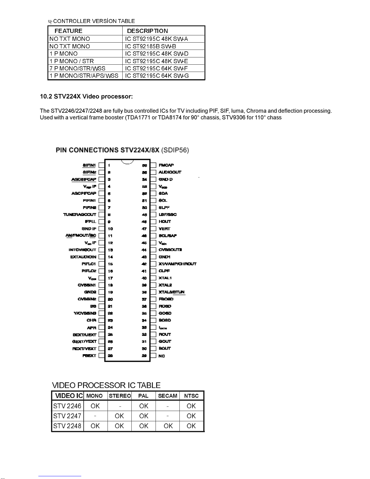
10.2 STV224X Video processor:
The STV2246/2247/2248 are fully bu controlled IC for TV including PIF, SIF, luma, Chroma and deflection proce ing.
U ed with a vertical frame boo ter (TDA1771 or TDA8174 for 90° cha i , STV9306 for 110° cha i ), they allow the
de ign of multi- tandard (BGDKIMNLL, PAL/ SECAM/NTSC) et with very few external component and no manual
adju tment .
679
679
679
2.
2.
2.
2.2. 2.
2.2. 2. 2.
2.
9,'(2,&
0212 67(5(2 3$/ 6(&$0 176&
9
,'(2
352&(6625
,&
7$%/(

8
10.3 UV1315, UV1316, UV1336
General description of UV1315
The UV1315 tuner belong to the UV 1300 family of tuner , which are de igned to meet a wide range of application . It i a
combined VHF, UHF tuner uitable for CCIR y tem B/G, H, L, L, I and I.
Features of UV1315
·Member of the UV1300 family mall ized UHF/VHF tuner
·Sy tem CCIR:B/G, H, L, L, I and I; OIRT:D/K
·Voltage ynthe ized tuning (VST)
·Off-air channel , S-cable channel and Hyper-band
·Standardized mechanical dimen ion and pinning
PINNING PIN VALUE
1. Gain control voltage (AGC) : 4.0V, Max:4.5V
2. Tuning voltage
3. High band witch : 5V, Min:4.75V, Max:5.5V
4. Mid band witch : 5V, Min:4.75V, Max:5.5V
5. Low band witch : 5V, Min:4.75V, Max:5.5V
6. Supply voltage : 5V, Min:4.75V, Max:5.5V
7. Not connected
8. Not connected
9. Not connected
10.Symmetrical IF output 1
11. Symmetrical IF output 2
Band witching table:
%$1'
3,1
3,1
3,1
/RZ
%DQG
9
9
9
0LG
%DQG
9
9
9
+LJK%DQG999
General description of UV1316:
The UV1316 tuner belong to the UV 1300 family of tuner , which are de igned to meet a wide range of application . It i a
combined VHF, UHF tuner uitable for CCIR y tem B/G, H, L, L, I and I.
Features of UV1316:
·Member of the UV1300 family mall ized UHF/VHF tuner
·Sy tem CCIR: B/G, H, L, L, I and I; OIRT: D/K
·Digitally controlled (PLL) tuning via I²C-bu
·Off-air channel , S-cable channel and Hyper-band
·World tandardized mechanical dimen ion and world tandard pinning
·Complie to CENELEC EN55020 and EN55013
PINNING PIN VALUE
1. Gain control voltage (AGC) : 4.0V, Max:4.5V
2. Tuning voltage
3. I²C-bu addre elect : Max:5.5V
4. I²C-bu erial clock : Min:-0.3V, Max:5.5V
5. I²C-bu erial data : Min:-0.3V, Max:5.5V
6. Not connected
7. PLL upply voltage : 5.0V, Min:4.75V, Max:5.5V
8. ADC input
9. Tuner upply voltage : 33V, Min:30V, Max:35V
10. Symmetrical IF output 1
11. Symmetrical IF output 2

9
General description of UV1336:
UV1336 erie i developed for reception of channel broadca t in accordance with the M, N tandard.
Features of UV1336
·Global tandard pinning
·Integrated Mixer-O cillator & PLL function
·Conform to CISPR 13, FCC and DOC (Canada) regulation
·Low power con umption
·Both Phono connector and F connector are available
PINNING PIN VALUE
1. Gain control voltage : 4.0V, Max:4.5V
2. Tuning voltage
3. Addre elect Max :5.5V
4. Serial cloc : Min :-0.3V, Max:5.5V
5. Serial data : Min :-0.3V, Max:5.5V
6. Not connected
7. Supply voltage : 5.0V, Min:4.75V, Max:5.5V
8. ADC input (optional)
9. Tuning upply voltage : 33V, Min:30V, Max:35V
10. Ground
11. IF output
10.4 TDA2822
General Description of TDA2822
The TDA2822 i a mono bridge amplifier pecially de igned for TV and Portable Radio application . Require very few
external component
WIDE SUPPLY VOLTAGE RANGE (3-15V)
MINIMUM EXTERNAL COMPONENTS
NO SVR CAPACITOR
NO BOOTSTRAP
NO BOUCHEROT CELLS
SHORT CIRCUIT PROTECTION
THERMAL OVERLOAD PROTECTION
PINNING
1. Output 1
2. Vcc
3. Output 2
4. Gnd
5. Input 2 (-)
6. Input 2 (+)
7. Input 1 (+)
8. Input 1 (-)
10.5 TDA8174AW
INDEPENDENT VERTICAL AMPLITUDE ADJUSTEMENT. BUFFER STAGE. POWER AMPLIFIER
FLYBACKGENERATOR. THERMALPROTECTION .INTERNAL REFERENCE VOLTAGE DECOU-PLING
General Description
TDA8174Aand TDA8174AWare a monolithic integrated circuit . It i a full performance and very efficient vertical deflection
circuit intended for direct drive of a TV picture tube in Color and B & W televi ion a well a in Monitor and Data di play .
PINNING
1. POWER OUTPUT
2. OUTPUT STAGE V
3. TRIGGER INPUT
4. HEIGHT ADJUSTMENT
5. VOLTAGE REF DECOUPLING
6. GROUND
7. RAMP GENERATOR
8. BUFFER OUTPUT
9. INVERTING INPUT
10. V
11. FLYBACK GENERATOR

10
10.6 UC3842/3
General description
DESCRIPTION
TheUC3842/3/4/5family of control IC provide the nece ary feature to implement off-line or DC to DC fixed frequency
current mode control cheme With a minimal external part count. Internally implemented circuit include under voltage
lockout featuring tart-up current le than 1 mA, a preci ion reference trimmed for accuracy at the error amp input, logic to
in ure latched operation, a PWM comparator which al o provide current limit control, and a totem pole output tage
de igned to ource or ink high peak current. The output tage, uitable for driving N-Channel MOSFET , i low in the off-
tate. Difference between member of thi family are the under-voltage lockout thre hold and maximum duty cycle
range . The UC3842 and UC3844 have UVLO thre hold of 16V (on) and 10V (off), ideally uited off-line application The
corre ponding thre hold for the UC3843 and UC3845 are 8.5 V and 7.9 V. The UC3842 and UC3843 can operate to duty
cycle approaching 100%. A range of the zero to < 50 % i obtained by the UC3844 and UC3845by the addition of an internal
toggle flip flop which blank the output off every other clock cycle.
General Features
OPTIMIZED FOR OFF-LINE AND DC TO DC
CONVERTERS
LOWSTART-UP CURRENT (< 1 mA)
AUTOMATIC FEED FORWARD COMPENSA-TION
PULSE-BY-PULSECURRENT LIMITING
ENHANCED LOAD RESPONSE CHARAC-TERISTICS
UNDER-VOLTAGELOCKOUTWITHHYSTER-ESIS
DOUBLE PULSE SUPPRESSION
HIGH CURRENT TOTEMPOLE OUTPUT
INTERNALLY TRIMMED BANDGAP REFER-ENCE
500 KHz OPERATION
LOWRO ERRORAMP
PINNING PIN VALUE
1. Comp Compen ation input
2. Vfb Error amplifier input (Regulation)
3. I Sen e Over current protection voltage 1V typ.
4. Rt/Ct Timing network
5. Ground
6. Output MOSFET driver
7. Vcc Supply voltage
8. Vref +5V Reference output
10.7 E²Eprom 24CO8
General description
The 24C08 i a 8Kbit electrically era able programmable memory (EEPROM), organized a 4 block of 256 * 08 bit . The
memory operate with a power upply value a low a 2.5V.
Features
Minimum 1 million ERASE/WRITE cycle with over 10 year data retention
Single upply voltage:4.5 to 5.5V
Two wire erial interface, fully I²C-bu compatible
Byte and Multi-byte write (up to 8 byte )
Page write (up to 16 byte )
Byte, random and equential read mode
Self timed programming cycle
PINNING PIN VALUE
1. Write protect enable : 0V
2. Not connected : 0V
3. Chip enable input : 0V
4. Ground : 0V
5. Serial data addre input/output : Input LOW voltage : Min : -0.3V, Max : 0.3*Vcc
: Input HIGH voltage : Min : 0.7*Vcc, Max : Vcc+1
6. Serial clock : Input LOW voltage : Min : -0.3V, Max : 0.3*Vcc
: Input HIGH voltage : Min : 0.7*Vcc, Max : Vcc+1
7. Multibyte/Page write mode : Input LOW voltage : Min : -0.3V, Max : 0.5V
: Input HIGH voltage : Min : Vcc-0.5, Max : Vcc+1
8. Supply voltage : Min :2.5V, Max : 5.5V

11
Saw filters list:
K2962/K2966
0
2
1
2
36%*'..// .0
/
36%*'..,, .0
3$/,, -
36%*'. .0
3$/%* *0
9,'(2 $8',2
PINNING
1. Input
2. Input-ground
3. Chip carrier-ground
4. Output
5. Output
L96 3M
PINNING
1. Input
2. Switching Input
3. Chip carrier-ground
4. Output
5. Output
12
0
2
1
2
,
)
1
9
0
,
&
.
(
<
3
$
'
,
5
6
(
1
6
2
5
9
9
$
8
'
9
6
0
3
6
8
&
6
7
9
&
9
,
'
(
2
3
5
2
&
(
6
6
2
5
6
7
0
,
&
5
2
&
2
1
7
5
2
/
/
(
5
5
*
%
$
0
3
$
8
$
0
3
7
'
$
'
L
V
F
U
H
H
W
$
P
S
7
'
$
$
:
9
(
5
$
0
3
)
%
7
+
2
5
,
=
2
1
7
$
/
'
5
,
9
(
%
8
'
)
9
,
'
(
2
6
:
,
7
&
+
,
1
*
&
,
5
&
8
,
7
6
6
&
$
5
7
)
$
9
3
/
/
9
6
7
7
8
1
(
5
8
9

13
AK36/TITANIUM TELETEXT Languages Groups
GROUP 1 - WEST
ENGLISH
FRENCH
SWEDISH
CZECH
GERMAN
PORTUGUESE
ITALIAN
RUMANIAN
GROUP 2 WEST / EAST
POLISH
FRENCH
SWEDISH
CZECH
GERMAN
SERBIAN
ITALIAN
RUMANIAN
GROUP 3 WEST / TURKEY
ENGLISH
FRENCH
SWEDISH
TURKISH
GERMAN
PORTUGUESE
ITALIAN
RUMANIAN
GROUP 4 EAST / CYRILLIC
ENGLISH
CYRILLIC
SWEDISH
CZECH
GERMAN
SERBIAN
LETTISH
RUMANIAN
GROUP 5 - ARABIC
ENGLISH
FRENCH
SWEDISH
TURKISH
GERMAN
HEBREW
ITALIAN
ARABIC
Using Coloured Buttons
RED : No function.
GREEN : I u ed to witch the a pect ratio between 4:3 and 16:9.
YELLOW : I u ed to prepare the y tem for creen-adju tment .
BLUE : No function.

14
AK36 CHASSIS MANUAL ADJUSTMENT PROCEDURE
In order to enter ervice menu, fir t enter the main menu and then pre the digit 4, 7, 2 and 5 re pectively.
To elect adju t parameter , u e or button . To change the elected parameter, u e or button .
Selected parameter will be highlighted.
Entire ervice menu parameter of AK36 CHASSIS are li ted below. For ome of parameter the default value are
given on the ame table.
REGISTER PARAMETER NOTE (NUMBERS ARE DEFAULT VALUES FOR CONCERNED ARAMETER)
OSD OSD Horizontal Position ADJUST HORIZONTAL POSITION FOR OSD
IF1 IF Coarse Adjust IF1 Adjust Course Ne . Adj. (WO / L)
IF2 IF Fine Adjust IF2 Adjust Fine Ne . Adj. (WO / L)
IF3 IF Coarse Adjust for L-Prime IF3 Adjust Course Pos. Adj. (W / L)
IF4 IF Fine Adjust for L-Prime IF4 Adjust Fine Pos. Adj. (W / L)
AGC Automatic Gain Control AGC Adjust AGC
VLIN Vertical Linearity ADJUST VERTICAL LINEARITY
VS1A Vertical Size for 50 Hz / 4:3 ADJUST VERTICAL SIZE FOR 4:3 MODE (50 HZ)
VS1B Vertical Size for 50 Hz / 16:9 ADJUST VERTICAL SIZE FOR 16:9 MODE (50 HZ)
VP1 Vertical Position for 50 Hz ADJUST VERTICAL POSITION (50 HZ)
HP1 Horizontal Position for 50 Hz ADJUST HORIZONTAL POSITION (50 HZ)
VS2A Vertical Size for 60 Hz / 4:3 ADJUST VERTICAL SIZE FOR 4:3 MODE (60 HZ)
VS2B Vertical Size for 60 Hz / 16:9 ADJUST VERTICAL SIZE FOR 16:9 MODE (60 HZ)
VP2 Vertical Position for 60 Hz ADJUST VERTICAL POSITION (60 HZ)
HP2 Horizontal Position for 60 Hz ADJUST HORIZONTAL POSITION (60 HZ)
RGBH RGB Horizontal Shift Offset CVBS RGB HORIZONTAL POSITION COMPENSATION
WR White Point Adjust for RED 40
WG White Point Adjust for GREEN 40
WB White Point Adjust for BLUE 40
BR Bias for RED 31
BG Bias for GREEN 31
APR APR Threshold 10
FMP1 FM Prescaler when AVL is OFF 9 (STEREO ONLY)
NIP1 NICAM Prescaler when AVL is OFF 20 (STEREO ONLY)
SCP1 SCART Prescaler when AVL is OFF 13 (STEREO ONLY)
FMP2 FM Prescaler when AVL is ON 13 (STEREO ONLY)
NIP2 NICAM Prescaler when AVL is ON 16 (STEREO ONLY)
SCP2 SCART Prescaler when AVL is ON 13 (STEREO ONLY)
F1H Hi h Byte of crossover frequency for VHF1-VHF3 MEANINGFUL FOR ONLY PLL TUNER (see tuner settin table)
F1L Low Byte of crossover frequency for VHF1-VHF3 MEANINGFUL FOR ONLY PLL TUNER (see tuner settin table)
F2H Hi h Byte of crossover frequency for VHF3-UHF MEANINGFUL FOR ONLY PLL TUNER (see tuner settin table)
F2L Low Byte of crossover frequency for VHF3-UHF MEANINGFUL FOR ONLY PLL TUNER (see tuner settin table)
BS1 Band Switch Byte for VHF1 Meanin ful for only MEANINGFUL FOR ONLY PLL TUNER (see tuner settin table)
BS2 Band Switch Byte for VHF3 Meanin ful for only MEANINGFUL FOR ONLY PLL TUNER (see tuner settin table)
BS3 Band Switch Byte for UHF Meanin ful for only MEANINGFUL FOR ONLY PLL TUNER (see tuner settin table)
CB Control Byte Meanin ful for only PLL Tuner MEANINGFUL FOR ONLY PLL TUNER (see tuner settin table)
OP1 Option 1 (see the Option List) PERIPHERAL OPTIONS (see option table)
OP2 Option 2 (see the Option List) RECEPTION STANDART OPTIONS (see option table)
OP3 Option 3 (see the Option List) VIDEO OPTIONS (see option table)
OP4 Option 4 (see the Option List) TV FEATURE OPTIONS (see option table)
OP5 Option 5 (see the Option List) CHANNEL TABLE OPTIONS (see option table)
TX1 Teletext Option 1 (see the Option List) TELETEXT OPTIONS (see option table)

15
USING COLOUR BUTTONS ON SERVICE MENU
RED BUTTON (For Stereo model only): It witche the AVL to ON or OFF mode on ervice menu. AVL word i vi ible on
ervice menu when AVL i on.
GREEN BUTTON : It witched the PICTURE MODE to 4:3 or 16:9 on ervice menu. It i u efull when it i nece ary to
adju t 16:9 picture mode vertical ize.
YELLOW BUTTON : It witche to VERTICAL SCAN DISABLE mode. It i u efull to adju t creen voltage.
BLUE BUTTON : It i u ed to adju t AGC and IF automatically on ervice menu.
WHITE BALANCE ADJUSTMENT
The following three parameter are u ed to make white balance adju tment. To do thi , u e a Colour Analy er. U ing WR
(White point adju t for RED), WG (White point adju t for GREEN), WB (White point adju t for BLUE) parameter , in ert
the + ign in the quare which i in the middle of the creen.
The ugge ted value for the e parameter are given on the table above.
AGC ADJUSTMENT
In order to do AGC adju tment, enter a 60dBmV RF ignal level from channel C-12 (224.25 MHz)
Select AGC parameter from ervice menu. Pre BLUE (INSTALL) button from remote controller. The adju tment will be
done automatically by oftware. See the AGC indicator on ervice menu, it mu t be 1. Check that picture i normal at
90dBmV ignal level.
,),1',&$725 $*&,1',&$725 121(
IF NEGATIVE ADJUSTMENT (WITHOUT L SYSTEMS)
Set the video pattern to a PAL colour bar pattern with frequency 38.9 MHz. Apply thi IF ignal to PIN-10 and PIN-11
of tuner. Pre PROG-1 and after that BLUE (INSTALL)button from remote controller. Select the tandart a BG or I.
(if BG i not available) Enter ervice menu. Select IF1 parameter from ervice menu and pre BLUE (INSTALL) button
from remote controller. IF adju tment will be done automatically by oftware. See the IF indicator on ervice menu, it
mu t be like on FIGURE-1 hown above.
IF POSITIVE ADJUSTMENT (WITH L SYSTEMS)
Set the video pattern to a SECAM-L colour bar pattern with frequency 33.9 MHz. Apply thi IF ignal to PIN-10 and
PIN-11 of tuner. Pre PROG-1 and after that BLUE (INSTALL)button from remote controller. Select the BAND VHF-1
(C1 C4 for PLL tuner ) and tandart a L(L for PLL Tuner). Enter ervice menu. Select IF1 parameter from ervice menu
and pre BLUE (INSTALL) button from remote controller. IF adju tment will be done automatically by oftware. See the IF
indicator on ervice menu, it mu t be like on FIGURE-1 hown above.
OSD HORIZONTAL POSITION ADJUSTMENT
Select OSD parameter on ervice menu. Adju t the horizontal po ition of OSD to the middle of creen, by u ing the
reference bar on bottom of ervice menu. (OSD adju t al o Horizontal po ition for text creen)
TELETEXT BRIGHTNESS ADJUSTMENT
Set the TV et to a channel with TeleText. Enter ervice menu. Pre TEXT button from remote controller. Adju t
BRIGHTNESS parameter to value 30 by u ing left-right button from remote controller. Pre TV button and MENU button
from remote controller re pectively. Adju tment i done.

16
9HUWLFDO/LQHDUW\9/,1
9HUWLFDO6L]H96$
9HUWLFDO6L]H96%
9HUWLFDO3RVLWLRQ93
+RUL]RQWDO3RVLWLRQ+3
9HUWLFDO6L]H96$
9HUWLFDO6L]H96%
9HUWLFDO3RVLWLRQ93
+RUL]RQWDO3RVLWLRQ+3
5*%02'(+RUL]RQWDO3RVLWLRQ5*%+
(QWHUD3$/%*FLUFOHWHVWSDWWHUQYLD5)&KDQJH9/,1WLOO\RXVHHFLUFOHDVURXQGDVSRVVLEOH
(QWHUD3$/%*FLUFOHWHVWSDWWHUQYLD5)&KDQJH96$9HUWLFDO6L]HWLOOKRUL]RQWDOEODFNOLQHVRQERWKWKHXSSHUDQGORZHU
SDUWRIWKHWHVWSDWWHUQEHFRPHYHU\FORVHWRWKHXSSHUDQGORZHUKRUL]RQWDOVLGHVRISLFWXUHWXEHDQGQHDUO\DERXWWRGLVDSSHDU
&KHFNDQGUHDGMXVW9HUWLFDO6L]HLWHPLIWKHDGMXVWPHQWEHFRPHVLPSURSHUDIWHUVRPHRWKHUJHRPHWULFDGMXVWPHQWVDUHGRQH
(QWHUD3$/%*FLUFOHWHVWSDWWHUQYLD5)(QWHUVHUYLFHPHQXDQGSUHVV*5((13,&785(EXWWRQIURPUHPRWHFRQWUROOHUWR
VZLWFKWRSLFWXUHPRGHRQVHUYLFHPHQX&KDQJH96%9HUWLFDO6L]HWLOOWKHSLFWXUHEHFRPHVIRUPDW&KHFNDQG
HDGMXVW9HUWLFDO6L]HLWHPLIWKHDGMXVWPHQWEHFRPHVLPSURSHUDIWHUVRPHRWKHUJHRPHWULFDGMXVWPHQWVDUHGRQH
(QWHU
D
3$/
%*
FLUFOH
WHVW
SDWWHUQ
YLD
5)
&KDQJH
9HUWLFDO
3RVLWLRQ
WLOO
WKH
WHVW
SDWWHUQ
LV
YHUWLFDOO\
FHQWUHG
+RUL]RQWDO
OLQH
DW
WKH
FHQWUHSDWWHUQLVLQHTXDOGLVWDQFHERWKWRXSSHUDQGORZHUVLGHRIWKHSLFWXUHWXEH&KHFNDQGUHDGMXVW9HUWLFDO3RVLWLRQLWHPLI
WKHDGMXVWPHQWEHFRPHVLPSURSHUDIWHUVRPHRWKHUJHRPHWULFDGMXVWPHQWVDUHGRQH
(QWHUD3$/%*FLUFOHWHVWSDWWHUQYLD5)&KDQJH+RUL]RQWDO3RVLWLRQWLOOWKHSLFWXUHLVKRUL]RQWDOO\FHQWUHG&KHFNDQGUHDGMXVW
+RUL]RQWDO3RVLWLRQLWHPLIWKHDGMXVWPHQWEHFRPHVLPSURSHUDIWHUVRPHRWKHUJHRPHWULFDGMXVWPHQWVDUHGRQH
(QWHUD176&0FLUFOHWHVWSDWWHUQYLD5)RUYLGHRLQSXWV&KDQJH9HUWLFDO6L]HWLOOWKHFKHFNHUHGSDUWVRIWHVWSDWWHUQRQERWKRI
XSSHUDQGORZHUVLGHGLVVDSSHDU&KHFNDQGUHDGMXVW9HUWLFDO6L]HLWHPLIWKHDGMXVWPHQWEHFRPHVLPSURSHUDIWHUVRPHRWKHU
JHRPHWULFDGMXVWPHQWVDUHGRQH
(QWHUD176&0FLUFOHWHVWSDWWHUQYLD5)RUYLGHRLQSXWV(QWHUVHUYLFHPHQXDQGSUHVV*5((13,&785(EXWWRQIURPUHPRWH
FRQWUROOHU
WR
VZLWFK
WR
SLFWXUH
PRGH
RQ
VHUYLFH
PHQX
&KDQJH
9HUWLFDO
6L]H
WLOO
WKH
SLFWXUH
EHFRPHV
IRUPDW
&KHFN
DQG
UHDGMXVW
9HUWLFDO6L]HLWHPLIWKHDGMXVWPHQWEHFRPHVLPSURSHUDIWHUVRPHRWKHUJHRPHWULFDGMXVWPHQWVDUHGRQH
(QWHUD176&0FLUFOHWHVWSDWWHUQYLD5)RUYLGHRLQSXWV&KDQJH9HUWLFDO3RVLWLRQWLOOWKHWHVWSDWWHUQLVYHUWLFDOO\FHQWUHG
+RUL]RQWDOOLQHDWWKHFHQWUHSDWWHUQLVLQHTXDOGLVWDQFHERWKWRXSSHUDQGORZHUVLGHRIWKHSLFWXUHWXEH&KHFNDQGUHDGMXVW
9HUWLFDO3RVLWLRQLWHPLIWKHDGMXVWPHQWEHFRPHVLPSURSHUDIWHUVRPHRWKHUJHRPHWULFDGMXVWPHQWVDUHGRQH
(QWHUD176&0FLUFOHWHVWSDWWHUQYLD5)RUYLGHRLQSXWV&KDQJH+RUL]RQWDO3RVLWLRQWLOOWKHSLFWXUHLVKRUL]RQWDOO\FHQWUHG
&KHFNDQGUHDGMXVW9HUWLFDO6L]HLWHPLIWKHDGMXVWPHQWEHFRPHVLPSURSHUDIWHUVRPHRWKHUJHRPHWULFDGMXVWPHQWVDUHGRQH
(QWHUD5*%FLUFOHWHVWSDWWHUQYLDYLGHRLQSXWV)RUFHWKH79WR5*%PRGHE\SUHVVLQJ$9EXWWRQIURPUHPRWHFRQWUROOHU
&KDQJH5*%+RUL]RQWDO3RVLWLRQWLOOWKHSLFWXUHLVKRUL]RQWDOO\FHQWUHG&KHFNDQGUHDGMXVW5*%+LWHPLIWKHDGMXVWPHQWEHFRPHV
LPSURSHUDIWHUVRPHRWKHUJHRPHWULFDGMXVWPHQWVDUHGRQH
+
]
1
7
6
&
3
,
&
7
8
5
(
$
'
-
8
6
7
0
(
1
7
6
+
]
3
$
/
3
,
&
7
8
5
(
$
'
-
8
6
7
0
(
1
7
6
50 Hz. 4:3 Geometry Adju tment 60 Hz. 4:3 Geometry Adju tment
50 Hz. 16:9 Geometry Adju tment 60 Hz. 16:9 Geometry Adju tment

17
OPTION SETTINGS
Select concerned OPTION from ervice menu. To change a bit on elected option pre the ame number from remote
controller. So thi bit will be changed from 1 to 0 or from 0 to 1. If any option i elected on ervice menu you will ee an
indicator row how you the bit number .
239LGHR2SWLRQV 127(
%,7
;WDO
&RQILJXUDWLRQ
3$/
RQO\
:2
176&
3OD\EDFN
%,7;WDO3$/3$/RQO\:176&3OD\EDFN
;WDO3$/176&3$/6(&$0:176&3OD\EDFN
;WDO3$/6(&176&3$/6(&$0:176&3OD\EDN
;WDO3$/6(&176&
%,7(QDEOH%OXHEDFNZKHQQRVLJQDOLQ$9PRGHGHIDXOWYDOXH
EODQNEDFNZKHQQRVLJQDOLQ$9PRGH
%,7:KLWH,QVHUWLRQLV21GHIDXOWYDOXH
:KLWH,QVHUWLRQLV2))
%,7%OXH%DFNJURXQGZKHQQRVLJQDOLQ79PRGH
'LVDEOH%OXH%DFNJURXQGLQ79PRGH
%,76HPLWUDQVSDUHQWEDFNJURXQGIRU26'GHIDXOWYDOXH
6ROLG0HQXEDFNJURXQGIRU26'
%,7%ODFN6WUHWFKLV21GHIDXOWYDOXH
%ODFN6WUHWFKLV2))
%,7$35LV21GHIDXOWYDOXH
$35LV2))

18
2379)HDWXUHV
127(
%,7+HDGSKRQHLVDYDLODEOHIRU67(5(2PRGHOV6WHUHR0RGHOVRQO\
+HDGSKRQH
LV
QRW
DYDLODEOH
ÕI
+3
OÕQH
LV
YLVLEOH
RQ
VRXQG
0HQ
%,7$UDELF3HUVLDQLVDYDLODEOHLQPHQXODQJXDJHV
$UDELF3HUVLDQLVQRWDYDLODEOHLQPHQXODQJXDJHV
%,7+HEUHZLVDYDLODEOHLQPHQXODQJXDJHV
+HEUHZLVQRWDYDLODEOHLQPHQXODQJXDJHV
%,7+RWHO0RGHFDQEHDFWLYDWHGGHIDXOGYDOXH
+RWHO0RGHFDQQRWEHDFWLYDWHG
%,71R6LJQDO7LPHULVHQDEOHGPLQFRXQWGRZQDQGVZLWFKRIIZKHQQRVLJQDO
1R6LJQDO7LPHULVGLVDEOHGGHIDXOGYDOXH
%,7)UHTXHQF\EDVHGVHDUFKIRU3//WXQHUÕIVHOHFWHGQHHGVWRVHOHFWDOVRFKDQQHO
&KDQQHOWDEOHEDVHGVHDUFKIRU3//WXQHU7DEOHVIURP237
QRPHDQLQJIRU967WXQHU
%,7EDQGWXQLQJ9+)9+)8+)GHIDXOWYDOXH
EDQGWXQLQJRQO\8+)
%,7([WUDPVHFEODQNLQJIRU967GHIDXOWYDOXH
QR
H[WUD
EODQNLQJ
7;7HOHWH[W2SWLRQV
127(
%,712786('GHIDXOWYDOXH
%,75(6(59('PXVWEHGHIDXOWYDOXH
%,77HOHWH[W/DQJXDJH*URXSV
%,7*URXS:HVW
%,7
*URXS:HVW(DVW
*URXS:HVW7XUNLVK
*URXS(DVW&\ULOOLF
*URXS$UDELF
%,7'HYLFHW\SHVHOHFWLRQIRU273,&XVH
%,7(35200$IRU0$6.,&XVH
%,7520+3
520/(66+3
(352005
52005
26'(352005273
520030$6.
5HDG$XWR*DLQ7DEOHIRUWKHGHYLFHIURP((3520
1RWH
7;
RSWLRQ
LV
YLVLEOH
6HUYLFH
0HQ
IRU
RQO\
ZLWK
7H[W
6:
9HUVLRQ
(QJOLVK)UHQFK6ZHGLVK&]HFK*HUPDQ3RUWXJXHVH,WDOLHQ5XPDQLDQ
3ROLVK)UHQFK6ZHGLVK&]HFK*HUPDQ6HUELDQ,WDOLHQ5XPDQLDQ
(QJOLVK)UHQFK6ZHGLVK7XUNLVK*HUPDQ3RUWXJXHVH,WDOLHQ5XPDQLDQ
(QJOLVK&\ULOOLF6ZHGLVK&]HFK*HUPDQ6HUELDQ/HWWLVK5XPDQLDQ
(QJOLVK)UHQFK6ZHGLVK7XUNLVK*HUPDQ+HEUHZ,WDOLHQ$UDELF

19
$
.
6
(
5
9
,
&
(
0
(
1
8
,
7
(
0
6
)
+
)
/
)
+
)
/
%
6
%
6
%
6
&
%
0
+
]
0
+
]
9
+
)
9
+
)
9
+
)
8
+
)
)
U
T
0
K
]
)
U
T
0
K
]
0
+
]
0
+
]
0
+
]
0
+
]
0
+
]
0
+
]
0
+
]
0
+
]
0
+
]
0
+
]
7
8
1
(
5
6
(
7
7
,
1
*
(
[
S
O
D
Q
D
W
L
R
Q
V
)
+
+
L
J
K
E
\
W
H
R
I
9
+
)
9
+
)
F
U
R
V
V
R
Y
H
U
I
U
H
T
X
H
Q
F
\
)
/
/
R
Z
E
\
W
H
R
I
9
+
)
9
+
)
F
U
R
V
V
R
Y
H
U
I
U
H
T
X
H
Q
F
\
)
+
+
L
J
K
E
\
W
H
R
I
9
+
)
8
+
)
F
U
R
V
V
R
Y
H
U
I
U
H
T
X
H
Q
F
\
)
/
/
R
Z
E
\
W
H
R
I
9
+
)
8
+
)
F
U
R
V
V
R
Y
H
U
I
U
H
T
X
H
Q
F
\
%
6
%
D
Q
G
V
Z
L
W
F
K
L
Q
J
E
\
W
H
I
R
U
9
+
)
%
6
%
D
Q
G
V
Z
L
W
F
K
L
Q
J
E
\
W
H
I
R
U
9
+
)
%
6
%
D
Q
G
V
Z
L
W
F
K
L
Q
J
E
\
W
H
I
R
U
8
+
)
&
%
&
R
Q
W
U
R
O
E
\
W
H
Other manuals for 11AK36-Vestel
1
Other Roadstar CRT TV manuals


