Roadstar TVD-1438 User manual

Service Manual -TVD-1438
R
TVD-1438

- 2 -
IMPOTANTSAFETYNOTICE
Manyelectricaland mechanicalpartsinthischassishavespecialsafety-related characteristics.Thesepartsare
identified byinthe SchematicDiagramand ReplacementpartsList.
It isessentialthatthesespecialsafetyparts’shouldbe replaced withthe samecomponentsasrecommended in
thismanualtopreventX-RADIATION,Shock,Fire,orotherHazards.
Donotmodifythe originaldesign withoutpermission ofmanufacturer.
SAFETY PRECAUTIONS
GeneralGuidance
An lsolation Transformer should always be used during
the servicing of a receiver whose chassis is not isolated
from the AC power line. Use a transformer of adequate
power rating as this protects the technician from accidents
resulting in personal injury from electrical shocks.
It will also protect the receiver and it’s components from
being damaged by accidental shorts of the circuitary that
may be inadvertently introduced during the service
operation.
If any fuse (or Fusible Resistor) in this TV receiver is blown,
replace it with the specified.
When replacing a high wattage resistor (Oxide Metal Film
Resistor,over 1w),keep the resistor 10mm away from PCB.
Keep wires away from high voltage or high temperature
parts.
Due to high vacuum and large surface area of picture tube,
extreme care should be used in handling the picture Tube.
Do not lift the picture tube by it’s Neck.
x-RAY Radiation
Warning:
The source of X-RAY RASIATION in this TV receiver is the
High Voltage section and the picture Tube.
For continude S-RAY RADIATIONprotection , the
replacement tube must be the same type tube as speci-
fied in the Replacement parts List
To determine the presence of high voltage,use an accu-
rate high impedance HV meter.
Adjust brightness, color,contrast controls to minimum.
Measure the high voltage.
The meter reading should indicate 23.5+1.5KV:14-19 inch,
26 +1.5kv:19-21inch,lf the meter indication is out of
tolerance,immediate serviceand correction is required to
prevent the possibility of premature component failure.
Before returning the receiver to the customer
always perform an AC leakag current check on the
exposed metallic parts of the cabinet,such as antennas,
terminals,etc;to be sure the set is safe to operate
without damage of electrical shock.
Leakage current cold check (Antenna cold check )
with the instrument AC plug renoved fron AC source,
connect an electical junper across the two AC plug prongs.
Place theAC switch in the on position, connect one lead of
ohm-meter to the Ac plug prongs tied together and touch
other ohm-meter lead in tum to each exposed metallic parts
such as antenna terminals,phone jacks,etc.
If the exposed metallic part has a return path to the chassis,
the measured resistance should be beween1MΩand 5.
2MΩWhen the exposed metal has no return path to the
chassis the reading must be infinite,An other abnormality
existsthatmustbecorrectedbeforethereceiverisreturned
to the customer.
Leakage Current Hot Check(See below Figure)
plug the AC cord DIRECTLY into the AC outlet.
Do notuse a line lsolation Transformer during this check.
Connect 1.5k/10watt resistor in parallel with a 0.15uF
capacitorbetween a known good earth ground (Water pipe,
Conduit,etc.)and the exposed metallic parts.
Measure the AC voltage across the resistor using AC
voltemeter with 1000 ohms/volt or more sensitivity.
Reverse plug the AC cord into the AC outlet and repeat AC
voltage measurements for each exposed metallic part.Any
voltage measured must not exceed 0.75 volt RMS which
is corresponds to 0.5mA.
In case any measurement is out of the limits specified,
there is possibility of shock hazard and the set must be
checked and repaired before it is retumed to the customer.
Leakage Current-Hot Check circuit
AC Volt-meter
To Instrument’s
exposed
METALLICPARTS
Good Earth Ground
such as WATER
PIPE,CONDUIT EIC
1.5Kohm/10W
0.15 uF

- 3 -
CAUTION:Beforeservicing receiverscovered bythisser-
vicemanualitssupplementsand addenda,read and follow
the SAFETYPRECAUTIONSon page 3ofthispublication.
NOTE:lfunforeseen circumstancescreateconflictbetween
the following servicing precautionsand anyofthe safety
precautionson page 3ofthispublication,always follow
the safetyprecautions.Remember:SafetyFirst.
GeneralServicing precautions
1.Always unplgthe receiverACpowercordfromthe AC
powersourcebefore:
a.Removing orreinstalling anycomponent,circuitboard
moduleoranyotherreceiverassembly.
b.Disconnecting orreconnecting anyreceiverelectrical
plug orotherelectricalconnection.
c.Connecting atestsubstituteinparallelwithan electro
lyticcapacitorinthe receiver.
CAUTION:Awrong partsubstitution orincorrectpolarigy
installation ofelectroiyticcapacitorsmayresultinan
expiosison hazard.
d.Discharging the picturetube anode.
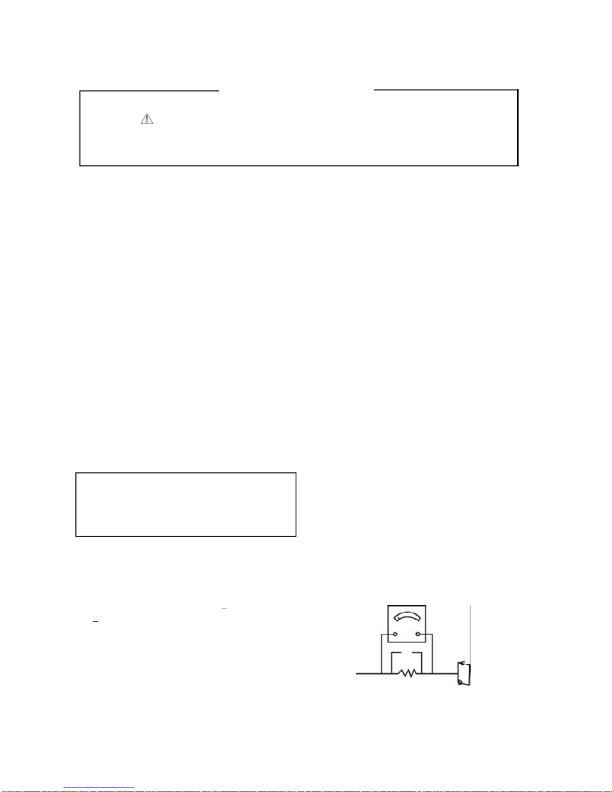
2.Testhigh voltage onlybymeasuring itwithan appropri
atehigh voltage meterorothervoltage measuring de
vice(DVM,FETVOM,etc)equipped withasuitablehigh
voltage probe.
Donottesthigh voltage by“drawing an arc”.
3.Discharge the picturetube anode onlyby(a)firstcon
necting one end ofan insulated cliplead tothe degauss
ing orkine aquadag grounding systemshieldatthe point
wherethe picturetube socketground lead isconnected,
and then (b)otuchthe otherend ofthe insulated diplead
tothe picturetube anode button,using an insulating
handietoavoidpersonalcontactwithhigh voltage.
4.Donotspraychemicalson ornearthisreceiveroranyof
itsassemblies.
5.Unless specified otherwiseinthisservicemanual,clean
electricalcontactsonlybyapplying the following mixture
tothe contactswithapipe cleaner,cotton-topped stick
orcomparablenonabrasiveapplicator:10%(byvolume)
Acetoneand90%(byvolume)isopropylalcohol(90%-90%
strength)CAUTION:Thisisaflammablemixture.
Uniess specified otherwiseinthisservicemanual,lubri
cation ofcontactsinnotrequire
6.Donotdefeatanyplug/socketB+voltage interlocks with
whichreceiverscovered bythisservicemanualmightbe
equipped.
7.DonotapplyACpowertothisinstrumentand/oranyof
itselectricalassembliesunless all solid-statedeviceheat
sinks arecorrectlyinstalled.
8.Always connectthe testreceiverground lead tothe re
ceiverchassisground beforeconnecting the testreceiver
positivelead.
Always removethe testreceiverground lead last.
9.Usewiththisreceiveronlythe testfixturesspecified in
thisservicemanusl.
CAITION:Donotconnectthe testfixtureground strap to
anyheatsinkinthisreceiver.
ElectrostaticallySensitive(ES)Devices
somesemiconductor(solidstate)devicescan be damaged
SERVICINGPRECAUTIONS
easilycalled ElectrostaticallySensitive(ES)Devices.Ex-
amplesoftypicalES devicesareintegrated circuitsand
somefieldeffecttraansistorsand semicounductor
“chip”components.Thefollowingtechniquesshouldbeused
tohelpreducethe incidenceofcomponentdamage caused
bystaticbystaticelectricity.
1.lmmediatelybeforehanding anysemiconductorcom-
ponentorsemiconducotr-equipped assembly.drainoff any
electostaticcharge onyourbodybytouchingaknownearth
ground.Alematively.
Obtainand wearacommerciallyavailabledischarging
wrislstrap device.whichshouldbe removed topreventpo-
tentialshock reasonspriortoapplying powertothe unit
undertest.
2.Afterremoving an electricalassemblyepuipped with
ESdevice.placethe assemblyon aconductivesurtacesuch
asaluminumfoil.topreventelectrostaticcharge buildup or
exposureofthe assembly.
3.Useonlyagrounded-tipsoldering iron tosolderor
unsolderES devices.
4.Useonlyan anti-statictype solderremovaldevice.
Somesolderremovaldevicesnotclassified as“anti-
static”can generateelectrecalchargessufficenttodemage
ES devices.
5.Donotusefreon-propelled chemicals.Thesecan gen-
erateelectricalchargessrffienttodamage ES devices.
6.DonotremovearepalcementES devicefromitspro-
tectivepackage until immediatelybeforeyou arereadyto
install it.(MostreplacementES devicesarepackage with
leadselectricall shorted togetherbyconductivefoam,
aluminumfoil orcomparableconductivematerial).
7.lmmediatelybeforremoving the protectivematerial
fromthe ieadsofareplacementES devicetouchthe pro-
tectivematerialtothe chassisorcircuitassemblyintowhich
the devicewill be installed.
CAUTION:Besureno powerisapplied tothe chassisor
circuitand observeall othersafetyprecautions.
8.Minmizebodilymotionswhen handling unpackaged
replacementES devices.(Otherwiseharmless motion
suchasthe bruching togetherofyourclothesfabricorthe
lifting ofyourfootfromacarpeted floorcan generatestatic
electricitysufficienttodamage an ES device.)
GeneralSoldering Guidelines
1.Useagrounded-tip.low-wattage soldering iron and
appropriatetipsizeand shape thatwill maintan tip
temperturewithen the range or500kto600k.
2.Usean appropriategauge ofRMAresin-coresolder
composed of60partstin/40partslead.
3.Keep the soldering iron tipclean and well tinned.
4.Thorohlyclean the surfacestobe soldered Useamall
wirebristle(0.5inch.or1.25cm)brushwithametalhandle.
Donotusefreon-propelled spray-on cleaners.
5.Use the following unsoldering technique
a.Allow the soldering iron tip to reach normal temperature
(500k to 600k)
b.Heat the component lead until tne solder melts.
c.Quicklydraw themelted solderwithananti-statlc,suc tion-

- 4 -
type solder removal device or with solder braid.
CAUTION:Work quickly to aviod overheating the
circuiboard printed foill.
6.Use the following soldering technique.
a.Allow the soldering iron tip to reach a normal temperature
(500k to 600k)
b.First,hold the soldering iron tip and solder the strand.
Against the component lead the solder melts.
C.Quickly move the soldering iron tip to the junction of the
compontent lead and the printed circuit foil and hold it
there oniy until the solder flows onto and around both
the component lead and the foil.
CAUTION:work quickly to avoid overheating the circuit
board printed foil.
d.Closely inspect the solder area and remove any excess
or splashed solder with a small wire-bristle brush.
IC Remove/Replacement
Some chassis circuit boards have slotted holes (oblong)
through wheic the IC leads are inserted’and then bent ftat
against the circuit foil. When holes are the slotted type the
following technique should be used to remove and replace
the IC. When working with boards using the familiar round
hole use the standard technique as outlined in parapraphs
5 and 6 above.
Removal
1. Desolder and straighten each IC lead in one operation
by gently prying up on the tead with soldering iron tip as
the solder melts.
2.Draw away the melted solder with an anti-static suction-
type solder removal device (or with solder braid) before
removing the IC.
Replacement
1.Carefully insert the replacement IC in the circuit board
2.Carefully bend each IC lead against the circuit foil pad
and solder it.
3.Clean the soldered areas with a small wire-bristle brudh.
(It is not necessary to reapply acrylic coating to the areas).
“Small-Signal” Discrete Transistor
Removal/Replacement
1.Remove the defective transistor by clipping its leads as
close as possible to the component body.
2.Bend into a “u” shape the end of each of three leads
renaining on the circuit board.
3.Bend into a “u” shape the replacement transistor leads.
4.Connect the replacement transistor leads to the corre
sponding leads extending from the circuit board and crimp
the “u”with long nose pliers to insure metal to metal to
metal contacttehn solder each connection.
Power Output, Transistor Device
Removal/Replacement
1.Heat and remove al solder from around the transistor
leads.
2.Remove the heatsink mounting screw (if so equipped).
3.Carefully remove the transistor from the heat sink of the
circuit board.
4.Insert new transistor in the circuit board.
5.Solder each transistor lead and clip off excess lead.
6.Replace heatsink.
Diode Removal/Replacement
1.remove defective diode by clipping its leads as close as
possible to diode body.
2.Bend the two remaining leads perpendiculay to the cir
cuit board.
3.Observing diode polarity wrap each lead of the new
diodearound the corresponding lead on the circuit board.
4.Secruely crimp each connection and solder it.
5.Inspect (on the circuit board copper side)the solder joints
of the two “original” leads. If they are not shiny reheat
them and if necessary apply additional solder.
Fuse and Conventional Resistor
Removal/Replacement
1.Clip each fuse or resistor lead at top of the circuit board
hollow stake.
2.Securely crimp the leads of replacement component
around notch at stak top.
3.Solder the commections.
CAUTION:Maintain original spacing between the replaced
component and adjacent component and the circuit board
to prevent excessive component temperaures.
Circuit Board Foil REPAIR
Excessive heat applied to the copper foil of any printed
circuit board will weaken the adhesive that bonds the foil
to the circuit board causing the foil to separte fron or “lift-
off” the board. The following guidelines and procedures
should be followed whenever this condition is encountered.
At IC Connections
To repair a defective copper pattem at IC connections use
the following procedure to install a jumper wire on the cop-
per pattem side lf the circuit board.9 (use this technique
ony on IC connections)
1.Carefully remove the damaged copper pattem with a
sharp knife.(Remove only as much copper as absolutely
necessary).
2.Carefully scratch away the solder resist and acrylic
coating(if used) from the end of the remaining copper
patten.
3. Bend a small “U” in one end of a small gauge jumper
wire and carefully crimp it around the IC pin.Solder the
IC connection.
4.Route the jumper wire along the path of the out-away
copper patten and let it overlap the previously scraped
end of the good copper pattem.Solder the overlapped
area and dip off any excess jumper wire.
At Other Connections
Use the following technique to repir the defective copper
pattem at connections other than IC pins.This technique
involoves the installation of a jumper wire on the compo-
nent side of the circuit board.
1.Remove the defective copper pattem with a sharp knife.
Remove at least 1/4 inch of copper,to ensure that a haz
ardous condition will not exist if the jumper wire opens.
2.Trace along the copper pattem from both sides of the
pattem break and locate the nearest component that is
directly connected to the affected copper pattem.
3. Connect insulated 20-gauge jumper wire from the lead
of nearest the nearest component on one side of the
pattem break to the lead of the nearest component.on
the other side,Carefully crimp and solder the connections.
CAUTION:Be sure the insulated jumper wire is dressed
so the it does ot touch componets or sharp edges.
SERVICING PRECAUTIONS

- 5 -
1. Speaker
2. Power Button
3. Remote Sensor
4. Channel Buttons
5. Open/Close Button
6. DVD Loader
7. Volume Buttons
8. DVD Play Button
9. DVD Stop Button
10. TV Menu Button
11. TV/AV/DVD Button
12. Earphone Jack
13. Video (1) Input
14. Audio(1) Input (R+L)
15. 75 Ohm Antenna Socket
16. Video/Audio(2) Input
17. Video/Audio Output
18. Audio digital Out Socket (For
DVD only)
LOCATION OF CONTROLS
1 12 4 6 8 10 12 14
3 5 7 9 11 13
15 16 1718

- 6 -
1. TV/AV Button
2. Standby Button
3. Numberic Buttons
4. TV Menu/Navigation Arrows Buttons
5. Channel Button
6. DVD Navigation Up Button
7. DVD Navigation Left Button
8. DVD Enter Button
9. DVD Menu Button
10. Pause/Step Button
11. Play Button
12. Stop Button
13. Zoom Button
14. Repeat Button
15. Subtitle Button
16. Search Button
17. Setup Button
18. Clear Button
19. Program Button
20. Open/Close Buttons
21. DVD/TV Buttons
22. Sleep Button
23. TV Display Button
24. Mute Button
25. PP Button
26. Volume Up/Down Buttons
27. DVD Navigation Right Button
28. DVD Navigation Down Button
29. DVD +10 Button
30. Fast forward Button
31. Fast backward Button
32. Next Button
33. Previous Button
34. Angle Button
35. Repeat A-B Button
36. Audio Button
37. Mark Button
38. DVD Display Button
39. Slow Play Button
40. Factory Button
LOCATION OF CONTROLS

- 7 -
OPERATING THETV
Using theremotecontrol
lAnyobjectbetween the remotecontroland the mainunitwill block the pathofthe beamwhen itis
being used.
l Darkwalls,directsunshine orverybrightlightwill reducethe remotecontrolsensitivety.
l Holdthe remotecontrolwithinan angleofabout30°fromeitherside ofthe remotesensor.
l When the remotecontrolisinfrontofthe remotesensor,itwill workwithinabout7meters(23 feet)from
the unit.
l Pointthe frontofthe remotecontroldirectlyatfrontofthe unit.
l Function keys do notworkwhen pressing severalkeys atthe sametime.
SPECIFICATION
l ColourSystemPAL
lPowerRequirementAC220V50Hz
lPowerconsumpion.90W
lStand-byconsumpion 10 W
l Tuning system:
VSTSystem
255 Programmememory
l Antemmainputimpedance:VHF/UHF75 ohm,unbalanced
l OSD(OnScreenDisplay): MENU Type
l Voice coil impedance:8ohm
l Sound output: mono 1.5WFROM14’’;2WFROM21’’
l ExternalIn/Output
Audio-In:0.5Vrms+3db,over10kohm
Audio-Out: 0.5Vrms+3db,below1kohm
Video-In/Out: 1Vp-p+3db,75 ohm
R,G,BIN:0.7VP-P+3db
l Feature:Autoprogramme
PSM(PictureStatusMemory)
8LANGUAGE:ENGLISH.SPANISH.FRENCH.GERMAN.ITALIAN.DUTCH.RUSSIAN.
PORTUGUESE.
ALIGNMENTINSTRUCTION
1.PLEASE READ BEFOREATTEMPTINGSERVICE
1.Donotconnectanyantenna plug directlytothe tunersocketand do notconnectanyequiprnentsdirectly
tothe TVchassis,otherwiseitmaybe burntoutthe TVorequipment,execeptan isolation transformerisused
formainpowersourceorthe TVsets.
2.Neverdisconnectanyleadswhilereveiverisinoperation.
3.Disconnectall powerbeforeattempting anyrepairs.
4.Donotshortanyportion ofthe circuitwhilepowerison.
5.Forsafetyreasons,all partsreplaced shouldbe identical(forpartsand patnumberssee partslist)
6.Beforealignmentthe setmustbe pre-heated for30 minutesormoreand erasemagnetismthoroughly
fromCRTfrontchassisframebyerasecoil.

- 8 -
TESTEQUIPMENT
1.ColourBar/Dot/Cross Hatch5.High Voltage Meter
2.Oscilloscope 6.AmpereMeter(0.5Class,DC 3mAMax.)
3.VacuumTube Voltmeter7.Demagnetizing Coil
4.VoltOhumeter8.Closed Caption Encoder
9.High PotTester
1.B+ADJUSTMENT
1.ConnetadigitalvoltmetertoB+and Ground.
2.SetBrightness Contresttominimum.
3.AdjustScreen Volumeon FBTuntil the picturecan justbeen seen.
4.AdjustVR901 toobtainareading of110+0.5VFrom21”,107V+0.5VFrom14”.
ALIGNMENTSTEP
1.Press the SERVICEbutton ofthe remotecontroltoenterintothe SERVICEMODE.
Press the numbericbutton 0-6toenterintothe SERVCJ0-6MENU.
2.Press button toselectrelevantitem.m.
3.Press button tochange the DATA.A.
4.Press the MENU button ofthe remoteocntroltoguitthe SERVICEMODE.
Remaks:
Press the picturePP button ofthe remotecontroltosetthe pictureto“STANDARD”.
||.VIFALIGNMENT(IFFS)
1.Enterintothe SEVICEMODESER.selectVIFFREQ.
2.Press the button toobtainacorrectDATA.A.
|||.AGCALIGNMENT(TOP)
1.Receivemonoscope patten atCH 69 and the inputsignalis62+3dB.
2.Connectadigitalvoltmeterbetween the TUNERAGCTerminaland ground.
3.Enterintothe SEVICEMODEand selectRF.AGC.ADJ.
4.Press button toadjusttothe maximumvalue’00’.
5.And then adjustthe value until the voltage drop down>0.4v.
Remark:a/. The drop downvoltage shouldbe morethan and tendsto0.4v.
b/. Noobservablenoisecan be seen.
IV.VERTICALALIGNMENT
1.Receivemonoscope patten.
2.Enterintothe SERVICEMODESERVCJ.0and selectthe following itemsV.SHIFT.V.SIZE.V.SCORR.
V.LIN
3.Adjustthe value ofthe aboveitemstoobtainanormalpicture.
V.HORIZONTALALIGNMENT
1.Receivemonoscope patten
2.Enterintothe SERVICEMODEand selectthe SERVCJ.0H.PHASE item.
3.Adjustthe Value toobtainthe pictureatcenter+2mm.

- 9 -
VI. G2VOLTAGEALIGNMENT
1.Receiveagreyscalepattern.
2.Enterthe SERVICEMODEtoselectthe TV.
3.Press the button then the TVwill becomeHorigontalLine.
4.Toadjustthe screen VRtomakethe HorigontalLine justilluminate.
5.Afterajustmentiscompleted,press the button then the TVScreen will becomeNormal.
VII. WHITEBALANCEALIGNMENT
1.Degauss the picturebydegaussing coil.
2.Receiveablack and whitepattern.
3.Enterintothe SERVICEMODEselect.DRIVE.R.DRIVE.B.CUTOFF.R.CUTOFF.G
CUTOFF.B.
4.Adjustthe value toobtainuniformlywhitepicture9300°k +3JND
VIII.SUB-BRIGHTNESS ALIGNMENT(SBRI)
1.Receiveagreyscalepattern.
2.Enterintothe SERVICEMODEselectSUB-BRI.
3.Adjustthe value until the brighness barcan justbe seen.
IX.FOCUSALIGNMENT
1)Setthe Brightness and Contrasttomiddleposition.
2)Reveiveamonoscope pattern.
3)Adjustfocuscontroltoobtainsharpestpicture.
X.HIGHPOTTESTING
1)Shortthe L-poleand N-poleofACline cord.
2)Switchon the powerswitchofthe TVset.
3)The High PotTester(-)connecttothe Land Npole,(+)tothe METALPARTofCABINET.
CONDITION
SAFETYSTD.TESTSTANDARD TESTSTANDARD
FORPRODUCTION
VDE,SAA 3.0KV 10mA/1MIN>3.5KV <10mA/>10SEC
BS 4.0KV 10mA/1MIN>4.0KV <10mA/>10SEC
CHINASTANDARD 3.0KV 10mA/1MIN>3.3KV <5mA/>6SEC
UL1.0KV 5mA/1MIN>1.25KV <5mA/>1SEC

SERVICE MODE ALIGNMENT STEPS
1. Press the FACTORY button to enter to the service mode.
2. Press the --/- button to change the desired item page.
3. Press the Navigation Arrows button / to choose the desired item to be adjust.
4. Press the Navigation Arrows button / the adjust the volume.
5. Press the TV MENU button to exit the service mode
FACTORY SETTING TABLE
SER VCJ0 (item page )Remarks DESCRIPTION
H PHASE 0 ~ 31 ★Horizontal Phase Adjustment For Horizontal Picture
Position Adjustment;
H VCO ADJ 0 ~ 7 ★Horizontal VCO Free Running Frequency Adjustment;
V SHIFT 0 ~ 7 ★Vertical Ramp Start Timing Adjustment For Vertical
Picture Position Adjustment;
V SIZE 0 ~ 63 ★Vertical Ramp Amplitude Adjustment For Vertical
Picture Size Adjustment;
V S CORRECTION 0 ~ 63 ★Vertical S Correction Adjustment;(For M61264 IC On
ly)
V LINEARITY 0 ~ 63 ★Vertical Linearity Adjustment; (For M61264 IC Only)
Y DL TIME ADJ 0 ~ 3 ◆Y Signal Delay Time Adjustment;
Y DL FINE ADJ 0 / 1 ◆Y Signal Delay Time Fine Adjustment;
SIGNAL 0 ~ 15 ◆Adjustment Signal Selection;
DR 0 ~ 127 ★R OUT Amplitude Adjustment;
DB 0 ~ 127 ★B OUT Amplitude Adjustment;
CR 0 ~ 255 ★R OUT Pedestal Level Adjustment;
CG 0 ~ 255 ★G OUT Pedestal Level Adjustment;
CB 0 ~ 255 ★B OUT Pedestal Level Adjustment;
VT 0 / 1 ★Vertical Ramp Out Stop Selection;
SUB-BRI 0 ~ 100 ◆Subsidiary Bright Adjustment;
V SYNC DET1 0 / 1 №
V SYNC DET2 0 / 1 №
V Sync Det 1/2 V Sync; Minimum time;
Det 1 Det 2
0 0 11.5usec
0 1 10usec
1 0 20.5usec
1 1 16.5usec
BGP FBP OFF 0 / 1 №BGP output system switching;
Status ‘0’= BGP is output regardless of FBP
‘1’= BGP is output only inside of FBP
S SLICE DOWN 0 ~ 3 №Sync separation slice level selection;
AUTO SLICE DOWN 0 / 1 №Sync detector slice level switch during video period;
Status‘0’= Slice level constant‘1’= Slice level
down during video period only
-10 -

TAKE OFF 0 / 1 №Chroma BPF/Take off switch; Compensate SAW Filt
er effect “1”=”Take off”; “0”=”BPF ”
C ANGLE 95 0 / 1 №Chroma relational angle of demodulationswitch;
Status‘0’= 103degree --Standard value;‘1’= 95d
egree;
EXT RGB C CLIP 0 / 1 №Effective on “On Screen Display ”only;
Status ‘0’= OSD level has low limit control
‘1’= OSD level is dependent on contrast control
C CLIP LEVEL 0 / 1 №C Clip Level Clipped contrast level;
0 = Low (32/128) ; 1 = High (48/128)
RF AGC ADJ 0 ~ 127 ★Tuner AGC Takeover Point Adjustment;
VIF VCO ADJ 0 ~ 63 ★VIF VCO Free-Running Frequency Adjustment;
VIF FREQ. 0 ~ 7 VIF VCO Frequency Selection;
VIF VIDEO OUT GAIN 0 ~ 7 №VIF Video Out (Pin58) Amplitude Control;
STRAP FINE ADJ 0 ~ 7 №Sound Frequency Adjustment;
STRAP FINE ADJ MSB 0 / 1 №Sound Frequency Adjustment MSB bit;
S TRAP OFF 0 / 1 №Sound trap frequency ON/OFF;
Status '0'= Sound Trap ON ;‘1’= Sound Trap OFF
OM DET 0 / 1 №Over-modulation detector ON/OFF;
Status ‘0’= Over-modulation detector OFF
‘1’= Over-modulation detector ON
AFT OUT LOW / OK / HIGH AFT OUT Display;
S TRAP Q UP 0 / 1 №Sound trap Frequency; Status '0' = Normal; '1' = Up
WHITE BACK 0 / 1 ★White Back Mode ON / OFF Selection;0=OFF; 1= ON
ABCL 0 / 1 №Auto Brightness And Contrast Limiter; 0=ACL (Auto
Contrast Limiter) Operation; 1=ABCL (Auto Brightn
ess And Contrast Limiter) Operation
ABCL GAIN 0 / 1 №ABCL Gain Low Or High Switch; 0=Low; 1=High
HALF TONE SWITCH 0 / 1 №Half Tone Function; 0=OFF(Normal Level); 1=Color
And Luminance Level Are Half
ANALOG OSD 0 / 1 №OSD input Analog/Digital switch; Status '0' = Digital
'1'= Analog
OSD LEVEL 0 / 1 №OSD output level switch; Status '0'= 70%; '1'= 90%;
Y SW LPF 0 / 1 №Y SW OUT, pin 31, LPF ON/OFF;
Status ‘0’= Flat ; ‘1’= LPF (fc = 700kHz)
If Y SW OUT is used both AV-out and CCD-out, do n
ot turn ON the Y SW LPF bit, because it occurs loss
high frequency in AV-out. In that case, make a filter
and insert as below.
VIDEO TONE GAIN SW 0 / 1 №Video Tone Gain Switch; 0=Standard; 1=Sharp
C TRAP FINE ADJ 0 ~ 3 №Chroma Trap Adjustment;
DOUBLE TRAP 0 / 1 №Chroma Double Trap Selection;
-11 -

BLK STRE. OFF 0 / 1 ◆Black Stretch Function ON / OFF; 0=ON; 1=OFF
BLK STRE. CHANG 0 / 15 ◆Charging time adjustment;
BLK STRE. DISCHA 0 / 15 ◆Discharging time adjustment;
BLK STRE. GAIN 0 / 1 ◆Black Stretch Gain Switch; 0=Normal; 1=Gain UP
GAMMA CONTROL 0 ~ 1 ◆Luminance Gamma Threshold Control; 0=Gamma
OFF;1~3=Gamma ON : 3 Modes
SECAM B L ADJ R 0 ~ 31
SECAM B L ADJ B 0 ~ 31
SECAM B F ADJ R 0 / 1
SECAM B F ADJ B 0 / 1
SECAM KILLER 0 ~ 3
SECAM Y DL
SECAM BGP SHIFT
SECAM OFF
U DL FINE ADJ 0 ~ 3
V DL FINE ADJ 0 ~ 3
V AGC
DVD OFF TIME 0 ~ 100 ◆DVD Power OFF Time Adjustment;
DVD TRI. TIME 0 ~ 250 ◆DVD Trigger Pulse Width Adjustment;
DVD TRI. DELAY TIME 0 ~ 30 ◆DVD Trigger Delay Time Adjustment;
CURTAIN SPEED ◆Curtain Speed Adjustment;
CURTAIN POS ◆Curtain Position Adjustment;
SAVER SPEED 0 ~ 10 ◆Screen Saver Speed Adjustment;
MENU STYLE 0 / 1 ◆Menu Style Setting;
0=Normal Menu; 1=Figure Menu
SOFTWARE VER. №Software Version;
INT AUDIO CON ON / OFF ◆Internal Audio Control And Mute Function Selection;
ON= Internal Audio Control And Internal Mute;
OFF=PWM Volume Control; Hardware Mute;
AUTO2 SYSTEM SEL 0 / 1 ◆Color System AUTO2 Function Selection; AUTO2 =
PAL –M & PAL –N & NTSC
DECODER CHOICE 0 / 1 ◆Decoder IC Selection; 0 = M61260 ; 1 = M61264
BALANCE SEL 0 / 1 ◆Balance Setting;
ON=W/ Balance Control; OFF=W/O Balance Control;
VIDEO OUT ON / OFF ◆VIF Detector Output Selection;
FACTORY KEY 0 / 1 ◆Factory Key Setting;1=Hot Key; 0=“Menu + Stan
dby ”;
MENU H POS 0 ~ 60 ★OSD Display Horizontal Position Adjustment;
MENU V POS 0 ~ 30 ★OSD Display Vertical Position Adjustment;
AV2 ON / OFF ◆AV2 Input Function Selection;
-12 -

SVHS ON / OFF ◆SVHS (Y / C) Input Function Selection;
YUV ON / OFF ◆YUV Input Function Selection;
DVD ON / OFF ◆DVD Input Function Selection;
DK ON / OFF ◆Sound System DK Function Selection;
I ON / OFF ◆Sound System I Function Selection;
BG ON / OFF ◆Sound System BG Function Selection;
M ON / OFF ◆Sound System M Function Selection;
AUTO1 ON / OFF ◆Color System AUTO1 Function Selection;
AUTO1 = PAL & NTSC & 4.43NTSC & SECAM
PAL ON / OFF ◆Color System PAL Function Selection;
NTSC ON / OFF ◆Color System NTSC Function Selection;
NTSC4.43 ON / OFF ◆Color System NTSC4.43 Function Selection;
SECAM ON / OFF ◆Color System SECAM Function Selection;
3.58PAL ON / OFF ◆Color System 3.58PAL Function Selection;
PAL –M ON / OFF ◆Color System PAL –M Function Selection;
PAL –N ON / OFF ◆Color System PAL-N Function Selection;
KILLER LEVEL 0 / 1 №Color Killer Sensitivity Threshold Switch;
Status ‘0’= 43dB ‘1’≈45dB
POWER ON MODE 0 ~ 2 ◆Power ON Mode Selection; 0=Standby; 1=Power
ON; 2=Status Of Power OFF;
□□□□□□□□□□
(0~9)
symbol
(A~Z)
◆Edit Logo Setting;
LOGO ON / OFF ◆Logo Setting Switch;
COLOR BLK/RED/
RE/YEL/BLU
PUR/CYA/WHI
◆Logo Color Selection;
Remarks:
Symbol ★:To be alignment by production Line.
Symbol : Not allow to adjust by production Line except production Engineer.◆
Symbol №: Not allow to adjust by production Line.
-13 -


5
5
4
4
3
3
2
2
1
1
D D
C C
B B
A A
of
CT908
CT908&MEMORY
LDON
RF_SDEN
RF_SDA
RF_SCK
LEI
FEI
TEI
SBAD
MIRR
STRACK
SFOCUS
SSLED
SSPDON
SMOTOR
TRAYOPEN
TRAYCLOSE
MOCTL-
OUTSW
INSW
HOMESW
STANDBY
SCART_SW
SCART_TV
SCART_RGB
CVBS1/Y
CVBS2
Y/CB
C/CR
MIC_MUTE
/ADC_RST
ADAC_CS0
ADAC_CS1
ADAC_SCK
ADAC_SDA
VSYN
HSYN
ACLK
PCMCLK
PCMWS
SPDIF+
ADC_SDA
RFO
PCMSD0
PCMSD1
PCMSD2
PCMSD3
CD_DVDSW
RF
SP3721&MOTO DRIVER
LDON
RF_SDEN
RF_SCK
RF_SDA
LEI
FEI
TEI
SBAD
SSPDON
SMOTOR
STRACK
TRAYOPEN
TRAYCLOSE
MOCTL-
OUTSW
INSW
HOMESW
SFOCUS
MIRR
SSLED
RFO
CD_DVDSW
POWER&AUDIO
POWER&AUDIO DAC
STANDBY
SCART_SW
SCART_TV
SCART_RGB
CVBS1/Y
CVBS2
Y/CB
C/CR
MIC_MUTE
/ADC_RST
ADAC_CS0
ADAC_CS1
ADAC_SCK
ADAC_SDA
VSYN
HSYN
ACLK
PCMCLK
PCMWS
SPDIF+
ADC_SDA
PCMSD0
PCMSD1
PCMSD2
PCMSD3
PCMSD2
HSYN
SBAD
SCART_SW
ADC_SDA
SMOTOR ACLK
RF_SCK
ADAC_SDA
CD_DVDSW
TRAYOPEN
PCMSD1
/ADC_RST
RF_SDA
OUTSW
INSW
CVBS1/Y
MOCTL-
STANDBY
TEI
LEI
SCART_TV
SSLED
PCMSD0
TRAYCLOSE
SFOCUS
STRACK
PCMCLK
SPDIF+
C/CR
PCMSD3
SSPDON
LDON
Y/CB
VSYN
HOMESW
ADAC_SCK
MIC_MUTE
SCART_RGB
FEI
RFO
MIRR
CVBS2
ADAC_CS0
RF_SDEN
PCMWS
ADAC_CS1

5
5
4
4
3
3
2
2
1
1
D D
C C
B B
A A
392P392P P5
C26
(181)
103P
5.1K 15K15K
HOP-1250
EACH POWER PIN -- A BYPASS CAPACITOR
R30
VFD PANEL
DV34
C150 CLOSE TO CT908
Value Table:
of
RFVT
SA18
MD4
MA9
MD0
SD7
SA13
MD3
SDCLK
MA5
MD12
IR_INT
OUTSW
SCART_RGB
SA1
/WR
MD8
MD10
MD10
MA11
SD5
MD10
/CAS
PCMCLK
MD7
MA1
SD6
BS1
BS1
SA13
MD9
TXD
OSC_O
VSYN
SA19
MA11
MD12
SD6
TEI
SA10
SSLED
OSC_I
RF_SCK
BS0
FEI
MD7 MA4
MD0
MD9
MD15
SA15
HOMESW
SDCLK
/CAS
MD5
MA3
CVBS2
SA4
SA15
MOCTL-
/FWR
IR_INT
MA5
MD13
RFO
MD4
MA0
MA5
/RAS
RFVT
MA2
MD8
MA10
/SCS
MA6
MD14
MA0
/RAS
ADAC_SDA
MD3
MD7
MD14
SA3
Y/Cb
MA4
RF_SDA
MA3
/FWR
MD7
MA7
MA8
SA16
TRAYCLOSE
MA3
MD1
SA19
MD15
SD5
MD15
SCART_SW
MA0
ACLK
MA7
ADAC_CS0
MA1
MD10
BS1
LDON
MD6
/PSEN
SD2
SA18
MD11
MA6
MA9
TXD
SA11
SA17
RF_SDEN
SA9
MA6
OP/CL
SD1
I2C_SDA
BS0
MA5
MA10
SA8
MD9
/CAS
MA6
MD0
/uPRST
SMOTOR
SFOCUS
DQM
SA10
MIRR
MD2
MD11
MD2
/RD
MD15
MD3
SD0
/SCS
/SCS
SA2
MD13
ACLK
MA9
INSW
I2C_SDA
SD4
SD2
I2C_SCK
MA0
ALE
SDCLK1
MD13
MD5
PCMSD1
SA6
LEI
SD0
STRACK
MD5
MD9
MA10
SPDIF+
SA17
SA1
ADAC_SCK
MA1
MD4
SDCLK1
/uPRST
MA4
SA5
/SCS
SA7
MD2
SA3
MA8
I2C_SCK
SA12
PCMWS
MA2
SA18
SA17
DQM
MA2
SA2
SA9
/ADC_RST
/WE
SD3
MD1
/WE
SA16
SA5
SBAD
PCMSD3
ADC_SDA
MA7
MD3
MD12
MD6
C/Cr
SA14
MA11
SD1
SA12
MD14
RXD
ADAC_CS1
MD6
MD5
/RAS
SA0
MA1
SA14
/WE
MD0 MD2
MD12
SA16
TRAYOPEN
MD13
/CAS
MA2
BS0
SA7
RXD
SA0
/RAS SA4
HSYN
BS0
PCMSD0
I2C_SDA
SA6
SA19
MD8
MD11
PCMSD2
MD6
MA4
MA7
MD11
MA8
/PSEN
MA3
/PSEN
MD8
MD1
SA11
SD3
SDCLK
SCART_TV
/WE
MA9
SSPDON
SD7
MA8
MA10
MD1
I2C_SCK
SA8
MD4
MD14
SD4
CVBS1/Y
/RESET
/PSEN
SA0
SA6
SA12
SA4
SD1
SA11
SD6
SA5
SA13 /FWR
SA16
SA1
SD5
SA18
SA10
SA7
SA2 SD2
SA15
SA9
SA8 SD7
SD4
SA14
SA17
SD0
SD3SA3
VFD_CS
VFD_CLK
PAUSE
VFD_CS
VFD_SDA
OP/CL
PAUSE
VFD_CLK
VFD_SDA
/RESET
+3.3VV
DGND
+1.8V
SGND
VDD
DGND
+3.3V
DGND
DGND
DGND
DGND
+3.3VS
DGND
VGND
DGND
DGND
DGND
+1.8V
+3.3V
VDD
FVCC
+1.8V
+3.3V
DGND
VDD
DGND
Flash_power
DGND
+3.3V
DGND
+3.3VS
DGND
DGND
Flash_power
SGND
DGND
DGND
+3.3V
SGND
+3.3V
+3.3V
+3.3VV
+3.3VS
DGND
MVREF2
DGND
DGND
DGND
+3.3V
Flash_power
+1.8V
VDD
DGND
Flash_power
+3.3V
+3.3V
+3.3V
+3.3V
R8
10K
W28J800B/T
U4
W28J800B/T
16
17
48
1
2
3
4
5
6
7
8
18
19
20
21
22
23
26
28
25
11
45
43
41
39
36
34
32
30
37 46
24
44
42
40
38
35
33
31
29
27
13
9
10
14
47
1512
A18
A17
A16
A15
A14
A13
A12
A11
A10
A9
A8
A7
A6
A5
A4
A3
A2
CE
OE
A0
WE
A-1/Q15
DQ14
DQ13
DQ12
DQ11
DQ10
DQ9
DQ8
VDD GND
A1
DQ7
DQ6
DQ5
DQ4
DQ3
DQ2
DQ1
DQ0
GND
VPP
NC
NC
WP
BYTE
RY/BYRESET
R11 68
C28
104P
C7
104P
R33
33
R15 0
R18 NU
C30
104P
R1 4.7K
R210 0
C8
100P
C49
104P
R2 4.7K
C22 104P
R3 4.7K
R27 30K
C17 10P
C27
104P
R4 4.7K
U5
W986416DH
34
33
32
31
30
29
26
25
24
23
18
17
16
15
2
53
51
50
48
47
45
44
42
13
11
10
8
7
5
4
1
14
27 54
12
63
9
43
41
46
28
22
35
19
39
38
37
40
36
21
20
49 52
A9
A8
A7
A6
A5
A4
A3
A2
A1
A0
RAS
CAS
WE
LDQM
DQ0
DQ15
DQ14
DQ13
DQ12
DQ11
DQ10
DQ9
DQ8
DQ7
DQ6
DQ5
DQ4
DQ3
DQ2
DQ1
VCC
VCC
VCC VSS
VSSQ
VSSQVCCQ
VCCQ
VCCQ
VSS
VSSQ
VSS
A10
A11
CS
UDQM
CLK
CKE
NC
NC
BS1
BS0
VCCQ VSSQ
R209 NC
C47
104P
R203
10K
R21410K
RN1
RN 33
1
2
3
45
6
7
8
R24 0
L1 FB600
L27 NC
R20810K
R5 10K
R21310K
C18 10OP
L26 0
C25
220P
R18710K
C9 104P
R238 100
C24
220P
L2 10uH
C303
104P
R30 15K
C32
104P
D3
RLS4148
C23
104P
Q1
2N9014
2
1 3
R31 10K
C39 104P
R26 30K
+
EC5
10u/16V
R7 10K
C20
104P
T431616A
U13 T431616A
32
31
30
29
28
27
24
23
22
21
17
16
15
14
2
49
48
46
45
43
42
40
39
12
11
9
8
6
5
3
1
25
10
47
13
38
50
41
26
18
36
35
34
37
33
19
44 47
20 A9
A8
A7
A6
A5
A4
A3
A2
A1
A0
RAS
CAS
WE
LDQM
DQ0
DQ15
DQ14
DQ13
DQ12
DQ11
DQ10
DQ9
DQ8
DQ7
DQ6
DQ5
DQ4
DQ3
DQ2
DQ1
VCC
VCC
VSSQ
VSSQVCCQ
VCCQ
VCCQ
VSS
VSSQ
VSS
CS
UDQM
CLK
CKE
NC
NC
BA
VCCQ VSSQ
A10
C14
102P
P5.0
L4 FB600
C6
104P
C3 47P
C34
104P
P5.0
C19
104P
R9 100
P5.0
C36
104P
C33
104P
+
EC1
100u/16V
C48
104P
U1
24C02/SOP
1
2
3
4
8
7
6
5
E0
E1
E2
VSS
VCC
MODE
SCL
SDA
C41
104P
T431616A
U17 T431616A
32
31
30
29
28
27
24
23
22
21
17
16
15
14
2
49
48
46
45
43
42
40
39
12
11
9
8
6
5
3
1
25
10
47
13
38
50
41
26
18
36
35
34
37
33
19
44 47
20 A9
A8
A7
A6
A5
A4
A3
A2
A1
A0
RAS
CAS
WE
LDQM
DQ0
DQ15
DQ14
DQ13
DQ12
DQ11
DQ10
DQ9
DQ8
DQ7
DQ6
DQ5
DQ4
DQ3
DQ2
DQ1
VCC
VCC
VSSQ
VSSQVCCQ
VCCQ
VCCQ
VSS
VSSQ
VSS
CS
UDQM
CLK
CKE
NC
NC
BA
VCCQ VSSQ
A10
C37
104P
J20
CON7
1
2
3
4
5
6
7
C35
104P
L3 FB600
C50
104P
CT908
U3
CT908
1
2
3
4
5
6
7
8
9
10
11
12
13
14
15
16
17
18
19
20
21
22
23
24
25
26
27
28
29
30
31
32
33
34
35
36
37
38
39
40
41
42
43
44
45
46
47
48
49
50
51
52
53
54
55
56
57
58
59
60
61
62
63
64
65
66
67
68
69
70
71
72
73
74
75
76
77
78
79
80
81
82
83
84
85
86
87
88
89
90
91
92
93
94
95
96
97
98
99
100
101
102
103
104
105
106
107
108
109
110
111
112
113
114
115
116
117
118
119
120
121
122
123
124
125
126
127
128
129
130
131
132
133
134
135
136
137
138
139
140
141
142
143
144
145
146
147
148
149
150
151
152
153
154
155
157
158
159
160
161
162
163
164
165
166
167
168
169
170
171
172
173
174
175
176
177
178
179
180
181
182
183
184
185
186
187
188
189
190
191
192
193
194
195
196
197
198
199
200
201
202
203
204
205
206
207
208
156
AVSS
AVDD18
VSS
MD0
MD1
MD2
MD3
VSSP
MD4
VDDP
MD5
MD6
MD7
VDD
MD15
MD14
MD13
MD12
VSSP
MD11
MD10
MD9
VSS
MD8
DQM
VDDP
SDCLK
SDCLKO
VSSP
MA11
MA9
MA8
MA7
MA6
MA5
VDDP
MA4
SWE
VDD
CAS
RAS
SCS
BS0
VSSP
BS1
VSS
MA10
VDDP
MA0
MA1
MA2
MA3
VLFA
AVSS
AVDD18
EMU
RESET
MIC_SD/D_REQ
VDD
ADCWS/D_ACK/CDSD
ADCCLK/DVD7
VSS
SPDIF/DVD6
VDD
PCMSD3/DVD4
PCMSD2/DVD3
PCMSD1/DVD2
PCMSD0/DVD1
PCMWS/DVD5
PCMCLK/DVD0
VSSP
ACLK/DVD_STC/CDCLK
VDDP
GPA4/Hsync/D_SYNC/CDWS
GPA5/Vsync/D_ERROR/C2PO
P5.7
P5.6
P5.5
P5.4
P5.3
VSS
P5.2
VDD
P5.1
P5.0
P4.7
P4.6
P4.5
P4.4
AVSS
AVO3
AVDD
AVSS
AVO2
AVDD
AVSS
AVO1
AVDD
AVSS
AVO0
AVDD
COMP
FSADJ
VREF
AVSSref
AVDDref
VSSDAC
VDDDAC
BSA19/P4.3
BSA18/P4.2
BSA17/P4.1
BSA16/P4.0
SA0
SA1
SA2
SA3
VSS
SA4
VDD
SA5
SA6
SA7
FWR
VSSP
SA8/P2.0
VDDP
SA9/P2.1
SA10/P2.2
SA11/P2.3
SA12/P2.4
SA13/P2.5
SA14/P2.6
SA15/P2.7
ALE
PSEN
SD0/P0.0
SD1/P0.1
SD2/P0.2
SD3/P0.3
VSS
SD4/P0.4
VDD
SD5/P0.5
SD6/P0.6
VSSP
SD7/P0.7
VDDP
RXD1/P3.0
TXD1/P3.1
INT0/P3.2
INTM/GPA6/P3.3
T0/P3.4
T1/P3.5
WR/P3.6
RD/P3.7
T2EX/P1.1
RXD2/P1.2
TXD2/P1.3
VSS
INTS/GPA7/P1.4
VDD
P1.5
P1.6
P1.7
VSSP
GPA3
GPA2
VDDP
GPA1
GPA0
C2POI/SMS3
CDWSI/SMS2
CDSDI/SMS1
CDCLKI/SMS0
D_REQI/SDEN/GPB9
D_ACKI/SDATA/GPB10
D_STCI/SCLK/GPB11
RFVT
RFIN
AVDD
LE
FE
TE
RFENV
FS
SRVM
FODAC
TRDAC
AVSS
D_SYNCI/SMA/SLPWM
SPDPWM
VSS
D_ERRORI/SMB/GPB8
DVDI7/TRAYPWM/GPB7
VSSP
OSCO
OSCI
VDDP
DVDI6/SPDFG/GPB6
VDD
DVDI5/LDON/GPB5
DVDI4/MTRSTBY/GPB4
DVDI3/SLHOME/GPB3
DVDI2/TRAYOUT/GPB2
DVDI1/TRAYIN/GPB1
DVDI0/TRAYCLOSE/GPB0
VLFM
T2/P1.0
R12 150
R13 4.7K
U18 W29C040/PLCC
12
11
10
9
8
7
6
5
27
26
23
25
4
28
29
3
2
22
24
1
31
13
14
15
17
18
19
20
21
30 16
32
A0
A1
A2
A3
A4
A5
A6
A7
A8
A9
A10
A11
A12
A13
A14
A15
A16
CE
OE
A18
WE
O0
O1
O2
O3
O4
O5
O6
O7
A17 GND
VDD
+
EC3
47u/16V
C42
104P
C10 104P
C16
104P
+
EC8
47u/16V
R6 10K
L6
FB600
+
EC7
47u/16V
R28
10K
JP1
4 HEADER
1
2
3
4
C26
392P
C1
104P
R29
10K
P5.0
C13
104P
R25 0
C4
104P
D2
RLS4148
R239 100
L5
FB600
C53
104P
R23
10K
R32 120
C11 102P
R14 3.3K P5.6
C43
104P
C52
104P
YM1
27M
C46
104P
+
EC9 10u/16V
R7
0
P4.3
D1
IN4148
C51
104P
C21
104P
C15
102P
C38
104P
R19 10K
R10
5.1K
C54
104P
+
EC4
47u/16V
R22
1M
C29
104P
R16 1M
R17 33
EC2
10u/16V
R21
4.7K
C1210P
HSYN
ADAC_CS0
SCART_TV
RF_SCK /ADC_RST
STRACK
CVBS1/Y
CVBS2
STANDBY
SSPDON
ADAC_SDA
RF_SDA
PCMSD3
RFO
HOMESW
ACLK
SMOTOR
SCART_RGB
VSYN
RF_SDEN
MIRR
ADAC_CS1
TRAYOPEN
INSW
SCART_SW
MIC_MUTE
LDON
LEI
Y/CB
PCMSD0
SSLED
TRAYCLOSE
PCMSD2
SFOCUS
TEI
PCMWS
IO_MUTE
PCMCLK
C/CR
MOCTL-
ADC_SDA
FEI ADAC_SCK
SPDIF+
OUTSW
CD_DVDSW
PCMSD1
SBAD

5
5
4
4
3
3
2
2
1
1
D D
C C
B B
A A
800mA
H = RGB OUT
L = CVBS OUT
800mA
AGND
AGND
SCART_RGB
MIC_L
GND
MIC_R
-12V
+12V
0-2V TV MODE1
12V(9.5V-12V 4:3)
6V(5V-8V 16:9)
SW_SCART
0
0
0
1
SCART_SW
0
SCART_TV
VGA FOR
P_SCAN
SPDIF Output
AGNDAGND
+12V
-12V
GND
GND
+5V
+3.3V
STANDBY
2ch only
selectable
to be cancel
POWER & AV OUTPUT.SCH
1.0
CT908 - SINGLE CHIP DVD SOLUTION
34Monday, March 01, 2004
Cheertek - Roadwell
Title
Size Document Number Rev
Date: Sheet of
PCMCLK
MR
ML
MUTE
AOUT_R
PCMWS
ACLK
AOUT_L
AOUT_L
MUTE
/ADC_RST
AOUT_R
CAP1
MIC_IN_R
MIC_IN_L
MIC_IN_R
MIC_MUTE
SCART_RGB
Y/Cb/B_O
CVBS1/Y/G_O
HSYN
C/Cr/R_O
VSYN
MIC_IN_L MIC_L
MIC_R
ML
MR
C/Cr/R_O2
Y/Cb/B_O2
ML
MR
SPDIF
CVBS2_O1
Y/Cb/B_O1
CVBS2_O
C/Cr/R_O1
AOUT_L
ACLK
CAP1
AOUT_R
I/O_MUTE
MUTE
MUTE
CVBS1/Y/G_O
CVBS2_O
Y/Cb/B_O
C/Cr/R_O
Y/Cr/B_O1
Y/Cr/B_O2
C/Cr/R/_O1
C/Cr/R/_O2
CVBS2_O1
CVBS1/Y/G_O
RGB
CVBS2_O2
RGB
SCART_RGB
CVBS2_O2
AGND
+3.3V_IN
VDD
+12VA
DGND
-12VA VDD
DGND
+1.8V
AGND
AGND
AVDD
DGND
DGND
VGND
AGND
+12VA
PGND
+5V
AGND
VDD
AGND
DGND
AGND
+12V
AGND
+3.3V
AVCC
DGND AGND VGND MGND PGND SGND
+12VA
-12VA
AGND
AVCC
VGND
AGND
VDD
DGND
DGND
AGND
DGND
DGND
VGND
VGND
VGND
AVDD
+3.3VS
+3.3V_IN +3.3VS
AGND
VDD
-12VA
AGND -12VA
AVDD
+5V
AVDD
VGND
+3.3VV
VGND
VGND
+3.3VV
+3.3VV
+3.3VV
VGND
VGND
VDD
VDD
C179
220u/10V
R199
33
EC25 10u/16V
+
EC20
10u/16V
R46
12K
C66
104P
Q13
2N9014
2
1 3
R45 2.2K
D5
RLS4148
R195 75
U7
AIC1117-3.3
1
23
GND
VOVI
C183
220u/10V
C76
102P
R190 1K
R169
33
P2
OPTICAL OUT
1
2
3
R196 75
R50
2K
C61
104P
EC30
10u/16V
C171100n
R41
4.7
C59
104P
C88
270P
R104 100K
Q2
2N9014
3
2
1
D9
RLS4148 J5
CON11_0
1
2
3
4
5
6
7
8
9
10
11
R57 331
EC12
47u/16V
D7
RLS4148
L25 FB80,1206
EC18
100u/16V
C101
270P
R40
4.7
C75 22P
+
-
U8B
4558
5
67
EC11
47u/16V
R54 2.2K
C73
104P
R96
120
D11
RLS4148
EC26 10u/16V
Q5
2N9014
2
1 3
J3
CON5
1
2
3
4
5
EC14
100u/16V
J2
CON7
1
2
3
4
5
6
7
C63
104P
R87
10K
P4
VIDEOPORT
21
43
76
5 8
9
C87
120P
EC13
100u/16V
R101
120
C96
330P
C62
104P
R51 1K
C85 22P
L11 FB80
R98
1.2K
P5
RCA-AV6
7
8
9
5
6
4
2
3
1
C60
104P
C71
104P
Q21
2N9014
2
1 3
U11 CT6630
1
2
3
4
5
6
78
9
10
11
12
13
14
15
16
DGND
DVDD
FSLR
DINLR
BCLK
VAGR
VORAGND
AVDD
VOL
VAGL
MODE
/RESET
DE1/DE0
SSP-EN/MUTE
XTALI
R100
15K
C99 22P
R38
220
R37 220(0805)
EC16
100u/25V
C83
330P
R182 2K
R43
100
R170
2.2K
Q3
2N9014
2
1 3
C172
22P
C93 22P
Q29 2N9014
2
1 3
C79
120P
Q27 2N9014
2
1 3
EC10
100u/16V
R172
91
R216 75
C68
104P
R39 220(0805)
C173
22p
D8
RLS4148
R198 75
J4
CON6
1
2
3
4
5
6
C58
104P
L24
FB600
C70
104P
R47
3.3K
C184
220u/10V
R66
75
+
EC39
47u/25V
L12 1.8uH
Q26 2N9014
2
1 3
U6
AIC1117ADJ
1
2
3
GND
VO
VI
D4
RLS4148
C89
330P
+
-
U8A
4558
3
21
C69
104P
R197 75
R191 4.7K
Q14
2N9015
C31
220u/10V
R167 68
R61 1K
C72
104P
C102
330P
C178
220u/10V
L23
FB600
C86
102P
R103
4.7K
R168
2.2K
C169
100P
R60
47K
EC17
100u/16V
D6
RLS4148
D13 RLS4148
R52
75
+
EC23
10u/16V
EC15
100u/25V
L13 1.8uH
L15 1.8uH
D14
RLS4148
D10
RLS4148
U20
WM8714
14
1
2
3
4 5
10
6
9
8
7
11
13
12
SCKI
LRCK
DIN
BCKIN
NC1 CAP
MUTE
VOUTR
VOUTL
VDD
GND
NC2
FORMAT
DEMP
C84 100P
C67
104P
Q28 2N9015
EC56
10u/16V
+
EC40
100u/16V
C95
270P
R200
100K
C176
104
R55
12K
L10 FB80
R88
820
R102
6.8K
R201
2.2K
R56
3.3K
L8FB80,1206
R63
75
R171 220
R44 22K
D15 RLS4148
R53 22K
C74 100P
R48 331
R73
75
Q30 2N9014
2
1 3
L14 1.8uH
Q22 2N9014
2
1 3
R215 75
Q24
2N9014
2
1 3
C170
104P
Q12
2N9014
2
1 3
R49
47K
Q25
2N9014
2
1 3
Q9
2N9014
2
1 3
Q4
2N9014
3
2
1
C40
220u/10V
C82
270P
MIC_MUTE
SCART_RGB
PCMSD3
SCART_SW
STANDBY
HSYN
VSYN
SPDIF+
PCMSD3
PCMCLK
PCMWS
SCART_TV
C/CR
CVBS2
Y/CB
CVBS1/Y
Table of contents
Other Roadstar CRT TV manuals