RollSeal RS-500 Series User manual

Part No. 4801-5166 Rev 10-2014 Owners Manual RS-500 Door
RS-500 Door
Installation Manual
RollSeal
1733 County Road 68
Bremen, Alabama 35033
256-287-7000

Page 2 D5/6 Series Doors MFZ Part No 4801-5166 Rev 10-2014
Table of Contents
1Ratings and Specifications .....................................................................................................................................3
2Warnings (Avertissements)....................................................................................................................................4
3Limited Warranty...................................................................................................................................................9
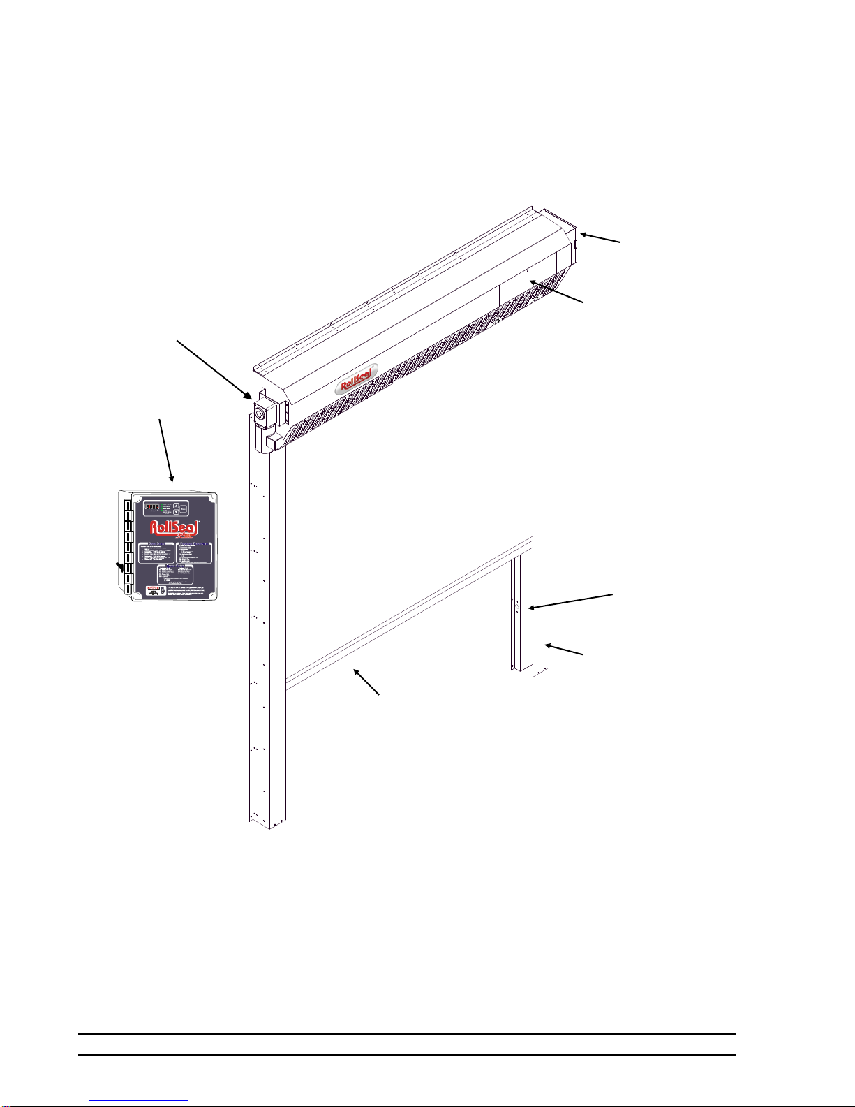
4Physical Description/Drawing..............................................................................................................................10
5Use of Equipment.................................................................................................................................................10
6Installation............................................................................................................................................................11
6.1 6.1 Tools Required....................................................................................................................................11
6.2 Overview ..................................................................................................................................................11
6.3 Adjusting the Clear Opening ....................................................................................................................11
6.4 Attachment Points of Door .......................................................................................................................12
6.5 Assembly of Parts.....................................................................................................................................13
6.6 Infrared Sensor Connectors ......................................................................................................................14
6.7 Fastening Door Assembly to Clear Opening ............................................................................................14
7Electrical Connections for RS500 Cooler Door...................................................................................................16
7.1 Connection of Controller to Head Unit.....................................................................................................16
7.2 Installing Prewired Switches ....................................................................................................................16
7.3 Power Connection with Disconnect..........................................................................................................17
7.4 Preparation for Operation .........................................................................................................................17
8Limit Switches .....................................................................................................................................................18
9Door Features.......................................................................................................................................................18
9.1 Warning Indicator Light ...........................................................................................................................18
9.2 Egress Strap ..............................................................................................................................................18
9.3 Egress Buzzer ...........................................................................................................................................18
10 Emergency Egress................................................................................................................................................19
10.1 Installation ................................................................................................................................................19
10.2 Exiting (Opening) The Door.....................................................................................................................19
10.3 Resetting (Closing) The Door...................................................................................................................20
11 Egress Strap Removal/Re-Installation..................................................................................................................21
11.1 Removal .......................................................................................................................................................21
11.1 Installation ................................................................................................................................................21
12 Manual Operation of Door...................................................................................................................................22
13 Adjustment of Brake ............................................................................................................................................23
14 Door Panel Adjustments.......................................................................................................................................24
15 Removal of existing Panel/Curtain Material........................................................................................................25
16 Installation of Replacement Curtain.....................................................................................................................26
17 RS-500 Door Wiring Diagram.............................................................................................................................27
Please Retain This Manual for Future Reference
Refer to SC-325 Controller Manual 4801-5156 and
D5/D6 Series Door Manual 4801-5154 for additional details.

Part No 4801-5166 Rev 10-2014 D5/6 Series Doors MFZ Page 3
1Ratings and Specifications
Motor Ratings: 240 VAC, Three Phase, 1/4 HP
Door approved by the NSF (National Sanitation Foundation)
Motor must be connected through Controller SC-325. See SC-325 Controller Manual (4801-5156).
TABLE 1 RS 500 Door Standard Dimensions:
WIDTH Related Dimensions HEIGHT Related Dimensions
RS500
Door
Width
A
D
E
Ft.
In.
cm
Ft.
In.
cm
Ft.
In.
cm
4'(W)
4
0
122
5
4-13/32
164
6
8-15/16
206
5'(W)
5
0
153
6
4-13/32
194
7
8-15/16
236
6'(W)
6
0
183
7
4-13/32
225
8
8-15/16
267
6'6"(W)
6
6
198
7
10-13/23
240
9
2-15/16
282
7'(W)
7
0
214
8
4-13/32
255
9
8-15/16
297
8'(W)
8
0
244
9
4-13/32
286
10
8-15/16
328
10'(W)
10
0
305
11
4-13/32
347
12
8-15/16
388
11'(W)
11
0
335
12
4-13/32
377
13
8-15/16
419
12'(W)
12
0
366
13
4-13/32
408
14
8-15/16
449
RS500
Door
Height
B
C
Ft.
In.
cm
Ft.
In.
cm
7'(H)
7
0
214
8
8-11/16
266
7'6"(H)
7
6
229
9
2-11/16
281
8'(H)
8
0
244
9
8-11/16
296
9'(H)
9
0
275
10
8-11/16
327
10'(H)
10
0
305
11
8-11/16
357
11'(H)
11
0
335
12
8-11/16
387
12'(H)
12
0
366
13
8-11/16
418

Page 4 D5/6 Series Doors MFZ Part No 4801-5166 Rev 10-2014
2Warnings (Avertissements)
Warning!
Disconnect All Power Sources Before Installing This Equipment. Failure To Disconnect
Power Source Can Result In Property Damage, Serious Injury Or Death!
Warning!
Dangerous Rotating Machinery!
Keep Hands, Clothing, Etc. Clear When Operating!
Do Not Operate Without All Guards And Covers In Place!
Warning!
All Wiring Should Be In Accordance with National Electrical Codes Or Other Local Codes.
Warning!
The Installer Is Responsible For Complying With All Relevant Regulations, Such As National
Wiring Regulations And Accident Prevention Regulations. Particular Attention Must Be Given
To The Cross-sectional Areas Of Conductors, The Selection Of Fuses Or Other Protection, And
Protective Earth/Ground Connections!
Warning!
The Voltages In The Power Cables And Certain Parts Of The Drive Can Result In Death.
Whenever The Drive Has Been Used, It Must Be Isolated And Disconnected For 5 Minutes
Before Any Work Commences.
!
!
!
!
!
!
!
!

Part No 4801-5166 Rev 10-2014 D5/6 Series Doors MFZ Page 5
Danger!
Only Qualified Electrical Personnel Familiar With The Construction And Operation Of This
Equipment And The Hazards Involved Should Install, Adjust, And/Or Service This Equipment.
Read And Understand This Manual In Its Entirety Before Proceeding. Failure To Observe
This Precaution Could Result In Severe Bodily Injury Or Death!
Warning!
IMPORTANT INSTALLATION INSTRUCTIONS
Warning!
To Reduce The Risk Of Severe Injury Or Death:
1. READ AND FOLLOW ALL INSTALLATION INSTRUCTIONS.
2. Do not connect the door operator to the source of power until instructed to do so.
3. Locate the control station: (a) within sight of the door, (b) at a minimum height of 5 feet
so small children cannot reach it, and (c) away from all moving parts of the door.
Remove all ropes and remove or make inoperative all locks connected to the garage
door before installing opener.
4.
For products having a manual release, instruct the end user on the operation of the
manual release. Where possible, install the door opener 7 feet or more above the floor.
For products having an emergency release, mount the emergency release within reach,
but at least 6 feet above the floor and avoiding contact with vehicles to avoid accidental
release.
!
Item 4501-6312
(Warning Moving Door Label)
Supplied With Door,
MUST Be Installed
On Inside Of Cooler/Freezer
Beside Door Opening.
!
!
!

Page 6 D5/6 Series Doors MFZ Part No 4801-5166 Rev 10-2014
IMPORTANT SAFETY INSTRUCTIONS
Warning!
To Reduce The Risk Of Severe Injury Or Death:
1. READ AND FOLLOW ALL INSTRUCTIONS!
2. Never let children operate or play with door controls. Keep the remote control (where provided) away
from children.
3. Personnel should keep away from a door in motion and keep the moving door in sight until it is
completely closed or opened. NO ONE SHOULD CROSS THE PATH OF A MOVING DOOR.
4. Test the door’s safety features at least once a month. After adjusting either the speed or the limit of
travel, retest the door operator’s safety features. Failure to adjust the operator properly may cause
severe injury or death. NEVER GO UNDER A STOPPED, PARTIALLY OPEN DOOR.
5. For products having a manual release, if possible, use the manual release only when the door is
closed. Use caution when using this release when the door is open.
6. KEEP DOORS PROPERLY OPERATING AND BALANCED. See Door Manufacturer’s Owner’s
Manual. An improperly operating or balanced door can cause severe injury or death. Have trained
door systems technician make repairs to cables, spring assemblies, and other hardware.
7. Install the Entrapment Warning label next to the control button in a prominent location. Install the
Emergency Release Marking. Attach the marking on or next to the emergency release.
8. After installing the opener, the door must reverse when it contacts a 1-1/2 inch high object (or a 2 x 4
board laid flat) on the floor.
9.
SAVE THESE INSTRUCTIONS.
French Translated Warnings
Avertissement!
Disjoindre fournissent de l'énergie tout les sources avant qu'installer cet équipement.
F|ailure| à disjoindre la source de pouvoir peut résulter dans dommage de propriété,
blessure sérieuse ou mort !
Avertissement!
Mécanisme tournant dangereux !
Garder les mains, vêtissant, etcC|lear| quand fonctionner !
Ne fonctionnez pas sans toutes gardes et couvertures dans lieu !
Avertissement!
Tout montage sur fil de fer doit être selon codes électriques nationaux ou autres
indicatifs régionaux.
!
!
!
!
!

Part No 4801-5166 Rev 10-2014 D5/6 Series Doors MFZ Page 7
Avertissement!
L'Installer est responsable pour conformer avec tout règlement pertinent, telles que
règlement et règlement de prévention d'accident de montage sur fil de fer nationaux.
Pl'attention articulaire doit être donnée pour les aires sectionnelles transversales de
conducteurs, le choix d'elles fusées ou autre protection, et terre / prises de terre
protecteur !
Avertissement!
Les tensions dans le pouvoir câblent et certains parties de la promenade en voiture
peuvent résulter dans la mort. Wle |henever| la promenade en voiture a été utilisé il
doit être isolé et détaché pendant 5 procès avant que tout travail commence.
Danger !
Seulement familier électrique de personnel qualifié avec la construction et opération
de cet équipement et les hasards ont enveloppé devoir installer, arranger, et/ou - la
révision cet équipement. R|ead| et comprendre ce manuel en entier avant que
procéder. F|ailure| à observer cette précaution peut résulter dans dommage corporel
sévère ou mort !
Avertissement !
!
!
!
Point 4501-6312
(Avertissement Moving étiquette de porte)
Livré avec porte,
doit être installé à
l'intérieur du réfrigérateur / congélateur
côté Ouverture de la porte.
!

Page 8 D5/6 Series Doors MFZ Part No 4801-5166 Rev 10-2014
LES INSTRUCTIONS D'INSTALLATION
IMPORTANTES
AVERTISSEMENT!
À réduire le risque de blessure sévère ou mort:
1. LU ET SUIVENT TOUTES INSTRUCTIONS D'INSTALLATION.
2. Ne liez pas l'opérateur de porte per la source de pouvoir jusqu'à instruit faire ainsi.
3. Localisez la station de commande: (a) en vue de la porte, (b) à un minimum la hauteur de 5
pieds ainsi petit enfants ne peuvent pas l'atteindre, et (c) loin de tous parties en mouvement
de la porte.
4. Pour produits ayant un délivrance manuelle, instruire l'utilisateur final sur l'opération de la
délivrance manuelle.
RÈGLEMENTS DE SÉCURITÉ IMPORTANTS
AVERTISSEMENT!
À réduire le risque de blessure sévère ou mort:
1. LU ET SUIVENT TOUTES INSTRUCTIONS!
2. Jamais laisser fonctionner enfants ou mouvoir vivement avec les autorités de porte. Gardez la
télécommande (où a fourni) loin des enfants.
3. Le personnel devrait garder loin une porte dans mouvement et subsistance la porte en
mouvement dans vue jusqu'à est complètement fermé ou avoir ouvert. CES AUCUNS DOIVENT
CROISER LE CHEMIN D'UNE PORTE EN MOUVEMENT.
4. Éprouvez les traits de sécurité de la porte au moins une fois par mois. Après qu'arrangeant la
vitesse ou la fin de course, retest les traits de sécurité de l'opérateur de porte. Manque à
arranger l'opérateur correctement peut causer blessure sévère ou mort.
5. Pour produits ai manuel la délivrance, si possible, utiliser la délivrance manuelle seulement quand
la porte est fermée. Précaution d'utilisation à utiliser cette délivrance quand la porte est ouverte.
6. GARDER LES PORTES CORRECTEMENT QUI OPÈRE ET ÉQUILIBRÉ. Voir la porte fabricant
propriétaire manuel. Un improprement qui opère ou balancé porte peut causer blessure sévère
ou mort. Formez les technicien de systèmes de porte faitez les réparations per les câbles,
réunions de source, et autre quincaillerie.
7. SAUVEZ CES INSTRUCTIONS.
!
!

Part No 4801-5166 Rev 10-2014 D5/6 Series Doors MFZ Page 9
3Limited Warranty
All products are warranted to be free from defects in material and workmanship for a period of one
(1) year or 100,000 cycles, whichever occurs first, from the date of purchase if installed and used
in strict accordance with the installation instructions. Liability is limited to the sale price of any
products proved to be defective or, at manufacturers’ option, to the replacement of such products
upon their return. No products are to be returned to the manufacturer, until there is an inspection
and/or a return-goods authorization (RGA) number is issued.
All complaints should be directed first to the authorized distributor who sold the product. If
satisfaction is not obtained or the name of the distributor is not known, write the manufacturer that
appears below, directed to the attention of Customer Service Manager.
This limited warranty is expressly in lieu of any and all representations and warranties expressed
or implied, including any implied warranty of merchantability or fitness for a particular purpose.
The remedy set forth in this limited warranty shall be the exclusive remedy available to any person.
No person has authority to bind the manufacturer to any representation or warranty other than this
limited warranty. The manufacturer shall not be liable for any consequential damages resulting
from the use of our products or caused by any defect, failure or malfunction of our products. (Some
areas do not allow the exclusion or limitation of incidental or consequential damages, so the above
limitation or exclusion may not apply to you.)
This warranty gives you specific legal rights and you may also have other rights that vary from area
to area.
Warrantor:
RollSeal
1733 County Road 68
Bremen, Al 35055
256-287-7000

Page 10 D5/6 Series Doors MFZ Part No 4801-5166 Rev 10-2014
4Physical Description/Drawing
Installation of a RollSeal RS-500 Automatic Door involves, at a minimum, connecting to the Smart Controller (SC-
325) that connects to the AC power, the door motor, the Up/Down button, and the safety beam. Other accessories
can be added such as a remote IR sensor, remote radio link, and door movement indicators such as lights and bells.
5Use of Equipment
The RollSeal RS-500 Door is an automatic motorized curtain enclosure for a doorway.
Encoder Box
Limit Switches are
located behind the
Access Panel.
See Section 8 for
Description of Limit
Switches.
Safety Beams
Tension Pipes are
located within folds of
curtain.
Floating magnets
and laminated steel
(attached to outside
of curtain and inside
track units).
Smart Controller
SC-325 or SC-650.
Motor
(230 VAC - 3 phase)

Part No 4801-5166 Rev 10-2014 D5/6 Series Doors MFZ Page 11
6Installation
6.1 Tools Required
3/8 in. (10 mm) Power screwdriver (portable)
3/16 in. (5 mm) Drill bit and power drill
3/8 x 1 in. Bolts and nuts (supplied)
Socket
Hammer
Tape measure
Carpenter's level
NOTE: Other Tools May Be Required According To Installation.
6.2 Overview
The RS-500 Door is shipped with pre-assembled vertical members (left track and right track), and a pre-
assembled horizontal member (head unit). When components are received, check for damaged, loose or
missing parts. If there are damaged or missing parts contact your RollSeal distributor immediately. Please
read and understand all instructions in this manual before beginning installation.
6.3 Adjusting the Clear Opening
Locate your particular system in Table 1, Page 3. Read the value of height and width of the clear opening for
the door size that you are installing. This gives the required dimensions of the clear opening. If necessary,
adjust the dimensions of the mounting posts or framing members to the height and width of your RS-500 Door
System as shown in Diagram 6A. Refer to Section 6.4 (Page 12, Diagram 6B) for details of attaching door
to framing members. Framing material must provide suitable support for attachment of screws.
Make sure that mounting posts or framing members are positioned so that the screw holes of the outer flanges
of the vertical members will align with the mounting posts or framing (Section 6.4, Page 12, Diagram 6B).
Make sure that there is room for the motor and control box without encountering any obstructions.
NOTE: Allow 1' (30.4 cm) minimum, preferably 18" (45.7 cm) clearance above the Head Unit for
future panel maintenance or replacement.

Page 12 D5/6 Series Doors MFZ Part No 4801-5166 Rev 10-2014
6.4 Attachment Points of Door
When sizing the clear opening for attachment of the door, pay close attention to the following guidelines.
Door flanges have pre-drilled holes that serve as mounting points of door.
Flange widths are shown in Diagram 6B.
1. Make sure that door assembly is plumb and square.
2. The top unit has a top flange and a bottom flange. Make sure these flanges overlap framing.
3. The vertical members have inner flanges and outer flanges. The outer flanges have pre-drilled holes that
serve as attachment points. Make sure the outer flanges overlap framing.
4. When door is raised in front of clear opening (Section 6.7, Page 14), flanges must be flush against framing
for attachment of screws.
Framing
Members
Framing Members
Bottom View

Part No 4801-5166 Rev 10-2014 D5/6 Series Doors MFZ Page 13
6.5 Assembly of Parts
Arrange the horizontal member, left vertical member (left track), and right vertical member (right track) on
the floor in front of the clear opening as shown in Diagram 6C. The curtain side of the horizontal member
and each vertical member faces down.
AB
Diagram 3
Placement of Parts for Assembly
Lay left track, right track, and horizontal
member face down in front of the
clear opening as shown.
Left vertical member
Right vertical member
Horizontal member
End of
horizontal
member
U-shaped
plate
Plate fits inside
vertical member
Slide vertical member
over U-shaped plate.
Vertical
Member
Clear Opening
At this end of members
3/8" x 1"
Bolts & nuts
On each end of the horizontal member
is a U-shaped plate that fits inside each
vertical member. The U-shaped plate
has four bolt holes, two on the inside
and two on the outside flanges that
match bolt holes in the vertical
member. See Diagram 6C.
1. Align the vertical member
with the U-shaped metal plate
at end of horizontal member.
2. Slide the vertical member
onto the outside of the U-
shaped metal plate of the
horizontal member as shown
in A.
3. Insert bolts through bolt holes
as shown in B. Install nuts.
Tighten bolts & nuts securely.

Page 14 D5/6 Series Doors MFZ Part No 4801-5166 Rev 10-2014
6.6 Infrared Sensor Connectors
Located at the bottom of each vertical member is an infrared detector. The detector on each vertical member
operates as a safety device if the infrared beam is interrupted. Door can be set to stop if beams are broken
while closing, or to stop and reverse to the full open position. Refer to the RollSeal SC-325 Controller
Manual for more information.
1. Locate female connector on vertical member. This connector is attached to the infrared detector.
2. Locate male connector on horizontal member. Unroll cable until connectors meet. Pull enough slack
for photo-eye replacement and troubleshooting purposes.
3. Plug connectors together. Make sure connectors interlock.
4. Repeat for both infrared detectors.
5. Cable ties and adhesive mounts are supplied to secure wire to the inside of tracks.
6.7 Fastening Door Assembly to Clear Opening
NOTE: For each vertical member,
unroll respective sensor cable attached
to horizontal member until cable
reaches the connector attached to the
vertical member. Plug connectors
together. Some slack must be left at
photo eyes for replacement purposes.
1. Use a tape measure and make sure
that the overall height and overall
width of the clear opening meet the
requirements: Overall Height = Height
+ 20.688 in. (52.55 cm), Overall Width
= Width + 16.4 in. (41.66 cm).
Reference Table 1, Page 3 and
Diagram 6A, Page 11.
2. Make sure that door assembly is
plumb and square. See Diagram 6E.

Part No 4801-5166 Rev 10-2014 D5/6 Series Doors MFZ Page 15
3. Center door assembly on clear opening. Align the bottom of
each vertical member with the respective framing board or
posts of the clear opening.
Note: The vertical members should be aligned so that
their outer flanges will exactly overlap with the
framing boards or posts when the door
assembly is raised into position.
4. Assemble workers and each side of the door
assembly. See Diagram 6F.
IMPORTANT: SLOWLY LIFT TOP OF DOOR
ASSEMBLY TO RAISE THE
DOOR.
5. Lean door assembly upright against clear opening.
6. Carefully press flanges of the door assembly flush against faces of framing boards or posts.
7. Fasten Tek screws (in steel) or lag screws (in wood) through the flanges on sides of door assembly.
Securely tighten all screws.
8. On the lower and upper flanges of the horizontal member there are attachment points for fastening
screws. Fasten Tek screws (in steel) or lag screws (in wood) through the holes. This secures the top of
the door to the clear opening.
9. Locate the two floor mounting holes at the bottom of the left & right tracks. See Diagram 6G.
10. Drill a 1/4"hole and install Hammer Set Anchors (1002-6030) in both right and left tracks. See
Diagram 6G.
11. This completes fastening of the door assembly to the clear opening.
Drill 1/4" Hole and
Install Hammer Set
Anchors

Page 16 D5/6 Series Doors MFZ Part No 4801-5166 Rev 10-2014
CPC
Control
Cooler
Wall
Outside
Switch
Inside
Switch
Conduit
Straps
CPC
Covers
Drill a minimum of
1” hole.
7Electrical Connections for RS500 Cooler Door
The Cooler Setup is designed to enable door installers to completely install and test door operation. Electrician is
still required to connect power to door, but all switch and interface connections are made to be pluggable for ease of
installation.
7.2 Connection of Controller to Head Unit.
1. Mount controller at desired location within 3’ of junction box on
Head Unit.
2. Controller has and AC and DC harness prewired that connects to
head unit as shown in Diagram 7A.
7.3 Installing Prewired Switches
Cooler Switches are prewired with a CPC quick connect. You have two switch assemblies an Outside Cooler
with harness out the top that is 6’ long and an Inside Cooler with harness out the bottom that is 1.5’ long.
1. Connect Outside switch to Controller with
CPC connection. Push and turn CPC
connector until it’s
completely locked in place.
2. Mount Outside Switch in
desired location on cooler
wall.
Note: Cover removed for mounting.
3. Drill 1” hole through Cooler
Wall to run Inside Switch out
to connect to Outside Switch.
4. Route Inside Switch Harness
through hole and connect to
bottom of Outside Switch
with CPC.
5. Mount Inside Switch in desired
location.
Note: Cover removed for mounting.
6. Install Conduit Straps on conduit
as required. Mount a strap close to
CPC connection to prevent tampering.
Insure conduit is run in a way to
prevent moisture from running
into electrical units.
7. Seal hole
DC Plug
AC Plug

Part No 4801-5166 Rev 10-2014 D5/6 Series Doors MFZ Page 17
7.4 Power Connection with Disconnect
1. Mount Disconnect in desired location.
2. Connect harness from Disconnect to
Control with CPC. Push and turn to lock in
place.
3. Remove Disconnect cover. Switch must be
in off position to remove cover.
4. Connect conduit and electrical supply to
Disconnect.
5. Connect 120V power supply to Disconnect
as shown in Diagram 10.
6. Place cover back on Disconnect.
7. Add conduit straps to conduit.
7.5 Preparation for Operation
Refer of the RollSeal SC-325 Controller Manual for more information on Controller Settings.
Note: If you detect any problems, STOP. Disconnect electrical power. Contact your distributor for
assistance.
1. Insert fuse in Control.
2. Apply 120VAC power to Control and turn Control toggle switch on.
3. Press “Open” button on Outside Switch. Door should open all the way to home limit switch and
reverse a few inches.
4. Depending on setup, door will time out and automatically close if safety beams are clear. If not setup
to automatically close, press “Close” button on Outside Switch and door should close.
Note: If door doesn’t close completely, follow limit setup procedure in SC325 Controller Manual
4801-5156.
5. Press “Open” a couple times to insure proper operation.
6. Repeat steps 3, 4 and 5 for Inside Switch.
7. Verify Safety Beams reverse door when blocked during closing.
8. Verify Leading Edge Switch is operational.
9. Ensure Safety Pull Hook for Egress is mounted inside cooler and Manual Crank Handle for motor is
mounted outside.
The door is now ready for operation.
Ground
L1 - Hot
L2 –Neutral
120VAC
10A
CPC
Control
Disconnect

Page 18 D5/6 Series Doors MFZ Part No 4801-5166 Rev 10-2014
8Limit Switches
The controller keeps track of the "open" and "closed" positions of the door by means of a mechanical encoder wheel
that is located in the control box. The controller electronically counts steps as the wheel turns to keep track of the
door position.
There are three limit switches
located within the horizontal
member mechanism. See
Diagram 8A. These switches are
attached to levers that contact the
curtain.
The Home Switch establishes the
'open' reference position of the
door curtain. This creates the
zero reference position, from
which the encoder counts the
position of the door.
The Safety Switch is a fail-safe
switch that stops the curtain in the
unlikely event of malfunction of
the home switch.
The Leading Edge Switch is a
switch that stops the curtain in the
event of a doorway obstruction.
9Door Features
9.1 Warning Indicator Light
Any time the cooler door is opening or closing, this light will flash indicating movement of door.
Note: On the SC-325, P4 setting in program mode must be set to 0 for proper operation.
Note: This feature will not work on Interlock or Freezers using CMS unit.
9.2 Egress Strap
The Emergency Egress feature provides a simple and convenient way to open door in emergency situation
from inside the cooler should the door motor become inoperative due to a power failure or other conditions.
The Emergency Egress Strap is located at center top of door. The door is opened by using the Emergency
Egress Tool to hook D-Ring and pull strap down. Strap may be pulled by hand also. As strap is pulled, the
door will open up enough that person can exit cooler safely.
9.3 Egress Buzzer
In the event the Egress Strap has been pulled, a buzzer will sound from the Head Unit as long as door has
power. To turn buzzer off, the egress strap must be fully reset.
See Section 10.3 for information on re-setting the Egress Strap.
Home Switch
Encoder Box
Leading Edge
Switch
Safety Switch
AC Plug
DC Plug

Part No 4801-5166 Rev 10-2014 D5/6 Series Doors MFZ Page 19
10 Emergency Egress
The Emergency Egress feature provides a simple and convenient means of exiting a RollSeal RS-500 Door from the
inside of the structure should the door motor become inoperative due to a power failure or other conditions.
10.1 Installation
Install the two Strap Retainers (1040-8400) to the left or right side outside of door jamb as shown below. For
a wood framed door jambs use two #10 x1screws (1004-1386). For a metal framed door jamb use two
#8x1/2 Tek screws (1004-2492). See Diagram 10A.
Diagram 10A Diagram 10B
Diagram 10C
10.2 Exiting (Opening) The Door
1. Remove Emergency Egress Tool from the
retainers on the side of the door.
2. Connect the hook end of the tool to the D-Ring
on the top of the door frame. See Diagram
10B.
3. Pull down on the Egress Strap. The Door will
raise approximately half way up. The door will
open enough for a person to exit the structure.
See Diagram 10C.
.
Install the
Emergency Egress
Tool Retainers on
the door jam

Page 20 D5/6 Series Doors MFZ Part No 4801-5166 Rev 10-2014
10.3 Resetting (Closing) The Door
After the RollSeal RS-500 Door is opened by using the Emergency Egress Strap, the door must be carefully
re-set to ensure proper operation in the future.
1. Firmly hold strap. See Diagram 10D.
2. Press the Cam Buckle Release. SeeDiagram 10E.
3. Gradually feed strap through Cam Buckle until door is closed at bottom.
4. Return Emergency Egress Tool to retainers for future use.
5. Cycle the door up and down in normal operating mode to ensure proper re-setting of the door.
Adjust if necessary. Door should now function normally.
Diagram 10D
Diagram 10E
CAUTION!
When the Cam Buckle is released, the door will rapidly close unless tension is held on the strap.
Keep fingers away from buckle while closing.
!
Press the
Cam
Buckle
Release
Firmly
hold
strap.
Other manuals for RS-500 Series
3
Table of contents
Other RollSeal Door manuals
Popular Door manuals by other brands

Johnson Hardware
Johnson Hardware 111FD484 instructions

Ives
Ives 620 Series installation instructions

BIRMINGHAM GARAGE & INDUSTRIAL DOORS
BIRMINGHAM GARAGE & INDUSTRIAL DOORS Industrial Door Operating and maintenance manual

Kaba
Kaba Simplex LP1000 Series owner's manual

Sterling Plumbing
Sterling Plumbing BATH CLASSICS 5970 Specifications

Ace
Ace Door user manual