ROSTSELMASH Strige ZTT-2.1 User manual

1

2

3
Rotary mower
“Strige”
Operation manual
Version 2

4
CAUTION! MOST IMPORTANT!
The mower is intended for bevelling of herbs in mowing strips in all zones of flat land use on fields
with the leveled relief.
Any other usage is to be a misuse. The Manufacturer is not responsible for any damage
hereupon.
To avoid hazards all persons operating or maintaining, repairing or checking this apparatus
shall read and complete indications of this Operating Instructions.
When studying this Operating Instructions pay attention to section 3 «Guidelines for safety
precautions».
Usage of non-original or blind spares and auxiliary equipment can have an adverse effect to
the mower designed characteristics or its serviceability and thus have an adverse effect to
active and passive motion safety and workmen’s protection (accident prevention).
The Manufacturer is not responsible fully for any hazard and damage due to usage of blind
parts and extra appliances, unauthorized apparatus construction changes performed by User.
Fulfillment of warranty obligations can be rejected to the apparatus Owner in case of accidental
or willful getting of foreign objects, materials, etc. into the internal or outside parts of item.
Terms «front», «aft», «right» и«left» should be understood from apparatus motion direction.
Due to constant operation on its product quality and fabricability improvement the
Manufacturer has a right to make changes in apparatus construction, that shall not be
reflected in the printed copy.
Address to central maintenance department in regard of all issues about mower
construction and maintenance:
2-6/22, 50-letiya Rostselmasha street
Rostov-na-Donu, 344065, Russia
phone /fax(863) 252-40-03 Web: www.KleverLtd.com
E-mail: service@kleverltd.com

5
DECLARATION OF CONFORMITY
ЕС
MANUFACTURER: JSC “KLEVER”
2-6/22, 50-letiya Rostselmasha Street
Rostov-na-Donu, 344065, Russia
Phone: + 7 (863) 255-22-00
AUTHORISED REPRESENTATIVE in EU:
SIA «Baltic Commerce Group»
Lubanas Str. 78, Riga, LV-1073, Latvia
Phone: +371-677-95225
Е-mail: baltic.commerce@gmail.com
TRADE MARK : Strige
PRODUCT TYPE : Rotary Mower
MODEL : ZTT-2.1
MODIFICATIONS : ZTT-2.4 , ZTT-2.8
APPLICATION : The mower is intended for bevelling of herbs in mowing strips. It is
applied in all zones of flat land use on fields with the leveled relief.
SERIAL NUMBER : __________________
We, “KLEVER” Ltd., DECLARED UNDER OUR RESPONSIBILITY that the product “Mower rotational
hinged ZTT-2.1” which this Declaration concerns, correspond to safety requirements and the
harmlessness, stated in the Directive 2006/42/EC (Appendix I, part 1, part 3).
For fulfillment of safety requirements and the harmlessness, following international standards have been
applied:
For fulfillment of safety requirements and the harmlessness, specified in the Directive 2006/42/EC,
following international standards have been applied:
EN ISO 4254-1:2009,EN ISO 4254-12:2012; EN ISO 4413:2010; EN ISO 12100-2010,
General Director
JSC “KLEVER” _______________________ A.M. Vinogradov
Rostov-na-Donu ________________ 20____

6
Content
Introduction .............................................................................................................................................. 7
This symbol determines instructions non-observance of which can cause hazard to life or health of
people or can lead to mower damage. ................................................................................................ 7
1. General................................................................................................................................................. 7
1.1. Purpose and application ...................................................................................................................... 7
1.2. Restrictions ........................................................................................................................................ 8
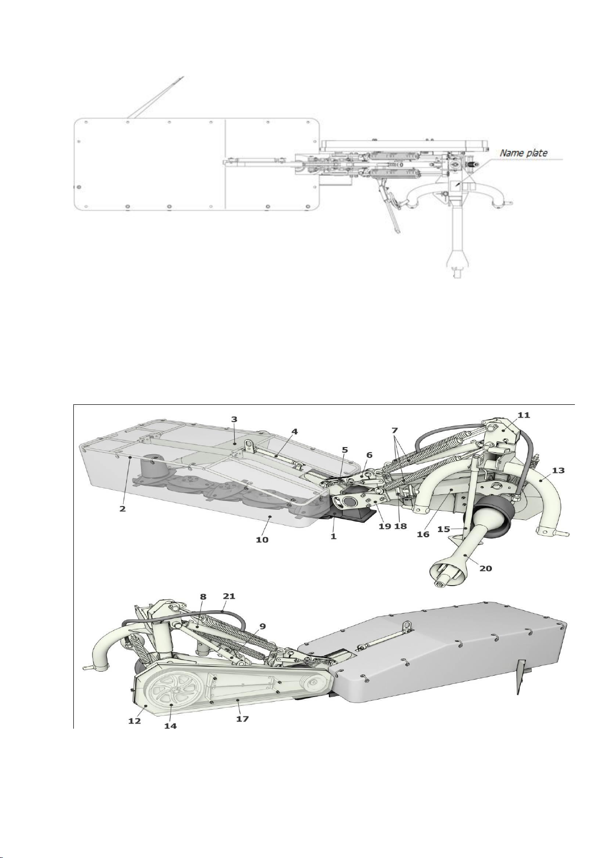
1.3. Mower name plate .............................................................................................................................. 8
1.4. General description of mower and its components ................................................................................ 9
1.5. Components description.....................................................................................................................11
2. Safety requirements..............................................................................................................................17
2.1.Safety requirements............................................................................................................................17
2.2. Warning plates ..................................................................................................................................18
3. Preparation for operation ......................................................................................................................23
3.1. Transportation...................................................................................................................................23
3.2. Final assembly...................................................................................................................................25
3.3. Tractor preparation for mower connection..........................................................................................25
3.4. Preparation of tractor hinged system ..................................................................................................25
3.5. Mower connection to tractor..............................................................................................................27
3.6. Mower haulage..................................................................................................................................27
4. Service and adjustment instructions.......................................................................................................28
4.1. Operation conditions ..........................................................................................................................28
4.2. Maintenance.....................................................................................................................................33
5. Maintenance ........................................................................................................................................34
5.1 General ..............................................................................................................................................34
5.2 Procedures performed during maintenance ..........................................................................................34
6. Storage................................................................................................................................................40
7. Apparatus recycling ..............................................................................................................................41
8. Delivery set ..........................................................................................................................................41
9. Manufacturer’s warranty .......................................................................................................................42
Appendix 1 ..............................................................................................................................................43
Appendix 2 ..............................................................................................................................................44
Appendix 3 ..............................................................................................................................................45
Appendix 4
..............................................................................................................................................46

7
Introduction
This Operating Instructions is intended for study the apparatus and service instructions of
mower ZTT-2,1 «Strige»and its modifications ZTT-2.4, ZTT-2,8 (hereafter - «mower»).
Operating Instructions contain main information about the apparatus, assembly, operation,
storage and transportation of the mower and safety precautions as well.
This symbol determines instructions non-observance of which can cause
hazard to life or health of people or can lead to mower damage.
1. General
1.1. Purpose and application
The mower (Fig. 1) is a hinged apparatus, its control and maintenance is carried out by
operator (tractor operator).
The mower is intended for bevelling of herbs with 60% wetness and yielding capacity more than 50
centner/ha when tractor is moving with speed 9 to 15 km/h.
Fig. 1.1. Mower ZTT
The mower is made in three modifications:
ZTT-2,1 –with 2.1 width of cut and output rate to 3.0 ha/h;
ZTT-2,4 –with 2.4 width of cut and output rate to 3.6 ha/h;
ZTT-2,8 –with 2.8 width of cut and output rate to 4.0 ha/h.
In this Operating Instructions mower ZTT-2,1 is considered to be the basic model and
structural features of mowers ZTT-2,4 and ZTT-2,8 are given in the respective sections of this
Operating Instructions.

8
1.2. Restrictions
The mower is serviceable under following ambient conditions:
•air temperature: 00Сto +400С
•field surface slope: to 8.50
•wind speed: to 12 m/s
Don’t operate mower in the time of thunder-storm.
It’s not recommended to use mower in stony soil.
Mower rotational hinged is unitized with tractors having the following characteristics:
•tractor power: 58.8 to 80 kW/h.p
•cardan shaft connection: 32 х38 Z8;
•speed of PTO: n=540 r.p.m.;
•oil supply: max. pressure is 20 MPa; rated pressure is 16 MPa.
1.3. Mower name plate
Mower name plate is shown in Fig. 1.2.
JSC “KLEVER”
2-6/22, 50-letiya Rostselmasha St.,
Rostov-na-Donu, 344065 Russia
Mower rotational hinged
Model
ZTT-2,1
Ident. No.
__________
Year 20
14
Productivity
3,0
ha/h
Mechanism mass, no more
460
kg
Warranty period
24
months
Fig. 1.2. ZTT-2,1 mower name plate
логотипа
компании

9
Place of name plate fitting is shown in Fig. 1.3.
Fig. 1.3. Place of name plate fitting
1.4. General description of mower and its components
1.4.1. General description of mower
Fig. 1.4. General view of mower ZTT-2,1

10
The mower (Fig. 1.4) is a hinged apparatus without worksite, it’s controlled and maintained by
operator (tractor operator).
Cutter bar 1 is a working element of mower, which is connected to bevel gear speed reducer
by threaded coupling.
Bevel gear speed reducer is fixed in plain bearing 19.
Two floated cutting blades attached to each rotor mounted on mower cutter bar.
Five rotational rotors mounted on mower ZTT-2,1, ZTT-2.4 has six rotors and mower ZTT-2,8
has seven opposite run rotors.
Three point hinge 13 is a main mower member with bracket 11 hinge mounted to swing mount
apparently to which the mower can run in horizontal plane when safety lock 18 is operating.
Bottom of swing mount is a hinge, allowing mower to rotate vertically during mower transfer
from transport position to on position and reverse one.
Small bar 16 is attached to swing mount bottom.
Four pins attach two plain bearings opposite bar end, where bevel gear speed reducer is
floated.
Except cutter bar tent frame 2 is fixed to the reducer, where tent 10 is mounted with use of
clamps.
Tent 10 and tent frame 2 provides access guarding to cutter bar, overlapping cut trajectory
more than 3 mm and they designed to prevent foreign objects coming out of working area as
well.
Tractional safety lock 18 is located under small bar.
Gear 14 with driving (big) pulley is attached to small bar on the bracket.
To protect V-belt drive the apparatus is furnished with protective removable housing 12,
attaching with use of captive bolts.
Cylinder actuator 8 serves for raising and lowering of small bar with all mounted assemblies on
it.
Connection of apparatus to tractor is carried out with use of hinge 13 and power transmission
–through telescopic cardan shaft with free-wheel clutch 20 guarded by protective housing 22.
When removing mower from tractor, the cardan shaft 20 is set to the sling (Fig. 1.11).
To prevent mower turnover when at idle (parking) state and transportation provision of stand
15 was made.
When operating mower, stand 15 should be fixed in uppermost position.
1.4.2. Operation of mower
Tractor draft force is used for mower operation.
Actuation of driven elements is performed from tractor power-takeoff shaft (PTO) through
telescopic cardan shaft.
Cutting of plants’ stems is carried out with use of segmented blades pivotally mounted on
rotors speeding with 65 m/s towards one another.

11
Blades cut herb on the principle of unsupported shear, pick up it and take out it from area of
shear, moving over cutting bar.
When striking the panel of outside divider the mowing herb is changing motion path, packing
into the swath and standing down for tractor wheels run during successive pass.
Swath width is set by swath former vanes motion.
1.5. Components description
1.5.1. Drive
Mower drive (Fig. 1.5) consists of bearing case 4, where bearings 2 are to be inserted.
Bearings are fixed with locking rings 3.
Shaft 1 is rotating in bearings, where three grooved pulley 5 is mounted.
Shaft torque is passing to pulley by tab to driven pulley 8 with help of belts 7.
Don’t allow excess or lowering of assigned limits in section 4.2.3.
Driving and driven pulley grooves should be in the same plane.
It’s achieved by relocation of shims from one side of bearing case to other one.
In this case difference between pulley groove planes should be 2 mm, max.
Рис. 1.5. Mower drive
1.5.2. Tractional safety lock
Tractional safety lock (Fig. 1.6) prevents cutter bar and reducer elements from damage during
collision of the bar with obstruction (invisible in grass stubs, stones, etc.).
Safety lock is connected with small bar by fork 6 and with hinge frame by hinged bearing 3.
Operation of safety lock is as follows:
When operating normally, link rod 4 and guide rod 2 are fixed with sheared element (pin) 5
from longitudinal motion and due to it the mower controls remain in normal (operating)
position. When hitting an obstruction, pin 5 becomes sheared permitting link rod 4 to move
freely along the guide rod 2 to stop 1.

12
In this case mower controls are steering relatively swing mount 12 (Fig. 1) backward along the
tractor movement, thus taking away cutter bar with reducer from obstruction, minimizing
possibility of cutter bar and reducer elements damage.
Tractional safety lock should activate under force of 3000 N (300 kg) applied to center part of
cutter bar.
To continue operation it’s required to raise mower on rear tractor hinge device that cutter bar
could drive off the ground and after that manually align holes of rod 2 and rod 4 and insert
new cut element (bolt).
Fig. 1.6. Tractional safety lock
1.5.3. Cutter bar with gear
Cutter bar (Fig. 1.7) is the main mower working element.
Rotors 2 installed on cutter bar, where fitted two cutting blades 3.
Five rotors mounted in mower model ZTT-2,1, six rotors mounted in model ZTT-2.4 and seven
opposite running rotors mounted in model ZTT-2,8.
Torque of tractor power take-off through cardan shaft with clutch, drive and V-belt drive is
transmitted to bevel gear speed reducer 4 and from there through train of gears to rotor
shafts.
Rotor blades attached floating and are self-centered into operating position when rotors are
running during mower operation under centrifugal effect.

13
Fig. 1.7. Mower cutter bar
It’s required to observe constantly for condition of mow out blades and
grease in reducer 4 and cutter bar. Missing of grease can cause bar and
reducer overheating and their malfunction.
1.5.4. Cutter bar balance unit
Balance unit (Fig. 1.8) is intended for provision of even pressure to the soil produced by cutter
bar over the whole area of panel bottom and profiling the roughness of soil relief as well.
Adjustment is carried out by tension screw of springs 7 (Fig. 1.4).
Pressure of external boot onto the soil should be within 200 to 300 N (20 to 30 kg), that
should be adjusted by springs 1, pressure of internal boot should be within 700 to 900 N (70
to 90 kg), that should be adjusted by spring 2 (Fig. 1.7).
Fig. 1.8. Balance unit
1.5.5. Functional diagram
Functional diagram of mower ZTT-2,1 is given in Fig. 1. 9.
Torque is transmitted from tractor rear power take-off shaft (PTO) through cardan shaft with
free wheel clutch to mower power reception shaft (PRC).
Then PRC transmit torque to cutter bar with reducer with help of V-belt drive.

14
Fig. 1.9. Functional diagram of mower ZTT-2,1
Fig. 1.10. Functional diagram of mower ZTT-2,4

15
Fig. 1.11. Functional diagram of mower ZTT-2,8
Functional diagram of mower ZTT-2,4 is given in Fig.10, mower TT-2,8 in Fig. 1.11.
1.5.6. Hydraulic system
Mower hydraulic system (Fig. 1.12) is made as a single-line one and consists of a cylinder
actuator Awith throttle B, high pressure sleeve Dwith joint quick disconnect clutch C.
Cylinder actuator Ais intended to put mower into stowage or operating position.
Non-adjustable throttle Bserves for setting of optimum speed of cutter bar lowering and
raising.
High pressure sleeve Dis designed to supply operating fluid to cylinder actuator A.
Quick disconnect clutch Cis designed to perform connection with tractor and preventing
operating fluid leaking during disconnection from tractor hydraulic system.
When disconnecting high pressure sleeve Dof mower hydraulic system from tractor hydraulic
system, it’s required to put special plug on quick disconnect clutch (Fig. 1.13).
Optimum high pressure sleeve Darrangement ensures missing of folds, bends and chaffing. E
is a direction of operating fluid running.

16
Fig. 1.12. Hydraulic system
Fig. 1.13. Arrangement of plug for quick disconnect clutch and latch for cardan shaft
fastening.
1.5.7. Specifications
Mower specifications are given in Table 1.1.
Table 1.1
Description
Mower model
ZTT-2,1
ZTT-2,4
ZTT-2,8
Type
Hinged
Output rate per 1 hour of main time, ha/h, up to
3.0
3.6
4.0
Working width, m
2.1
2.4
2.8
Mass without spares and package, max., kg
460±25
480±25
700±25

17
Dimensions, mm, max
length
2370±50
2370
2160
width
3700±50
4000
4560
height
1150±50
1050
1400
Dimensions along with tractor МТЗ-80, mm, max.
Operating position
length
5920
6230
width
3740
4500
4700
height
2540
Stowage position
length
5080
5450
5390
width
2700
2820
height
3090
3490
3890
Tractor ВОМ r.p.m.
540
Height of artificial grass cutting
8±2
Natural grass
6±2
Consumed power Kw, not more than
35
35
50
Speed, operating. Max., km/h
15
Transport speed, max., km/h
30
Level of sound pressure, dB(A)
70*
Service life, years
7
* So as it’s possible to determine the noise level with tractor operating, so actual
value depends on operated tractor mark.
2. Safety requirements
2.1.Safety requirements
2.1.1 General
The mower should be operated in compliance with the requirements of this Operating
Instructions, national safety and environmental standards, determining the requirements for
safety operator operation.
Only specialists allowed to perform this work that:
•instructed properly;
•being in equal physical and mental state: fresh, not be under alcohol, drug or
medicine effect;
•knowing mower operating instructions and safety norms and also having experience
in operating of this mower.
Operator (User) IS NOT ALLOWED to make changes in rotor mower.
2.1.2 Safety instructions during operation
DON’T DO THE FOLLOWING:
Inspect mower and perform its repair or maintenance with activated tractor PTO shaft;

18
Moving of tractor with mower without setting and fixing of cutter device vertically
(transport position);
When testing, to start and operate mower, location of unauthorized people at distance
less than 50 m from mower;
replace blades without preliminary lock of rotors from turning;
work with tractor doors and windows open when operating mower under conditions
causing dust pollution at tractor operator working station.
When starting and operating mower it’s required to do the following:
• check cutter device every four hours of operation;
ensure the cutting blades attachment to avoid their inadvertent separation during
operation;
check rotor attachment safety;
check area under rotors for foreign objects and in case of their availability remove
them.
When transporting the mower should be fixed in stowage position i.c.w. Fig. 4.1 and
requirements of section 4.
When loading and unloading fix mower to prevent it from folding i.c.w. Fig. 4.2 and
requirements of section 4.
Fire fighting measures:
- observe the tractor you operate should be equipped with fire extinguisher;
- don’t spill oil during greasing;
-clean mower from mowed off material.
2.2. Warning plates
When operating and maintaining mower it’s required to notice (follow) the warning symbols
and perform their requirements.
Locations and meaning of warning symbols are given in Table 2.1 and Fig. 2.1, Fig. 2.2.
Keep warning plates always clean with clear symbol image and preserve them during all
product service life.
Replace plates in case of loosing image clearness, change of color, integrity of plate shapes.
Fit new parts with the respective plates in case of their replacement.

19
Table 2.1
Nos
Symbol
Meaning of symbol
1
Common attention!
2
Switch off tractor ignition!
3
Warning!
Rotating parts!
4
Maintenance!
See Instructions!

20
Nos
Symbol
Meaning of symbol
5
Caution!
PTO shaft speed of tractor is
540 r.p.m.!
6
Warning!
Danger of winding on cardan
shaft!
7
Caution!
Hazard for hands!
8
Caution!
Hazard for feet!
9
Warning!
Staying of unauthorized
persons is not allowed at
distance less than 50 m !
This manual suits for next models
2
Table of contents
Popular Lawn Mower manuals by other brands

Wolf Garten
Wolf Garten Esprit 40 H instruction manual

Bushranger
Bushranger 53TBU65 Assembly and owner's manual

Land Pride
Land Pride Rotary Cutter RCR2684 Operator's manual

Cub Cadet
Cub Cadet RZT 50 (w/50" Mower Deck) Operator's manual

Webb
Webb WER18HP Original instructions

Swisher
Swisher POL 10550 owner's manual