Royal-Kincool GLACIAN GUC1737 User manual


This instruction manual is an integral part of the machine and must be kept for any further consultation.
Never try to use this machine for applications which are not described in the instructions or for the unit's
intended purpose.
This machine should be used only for the purpose for which it was designed. Any other use is
inappropriate and dangerous. The manufacturer will not be held responsible for any damage caused
by improper use.
Before installing and operating on the machine read the operation manual.
Unplug the machine from outlet when not in use, before putting on or taking off parts, and before
cleaning. Do not power unit through a power board or extension cord.
Be sure to unplug the machine if not using the machine for a long time.
If the supply cord is damaged, it must be replaced by the manufacturer, its service agent or licensed
electrician persons to avoid a hazard.
Do not use the machine in a dusty environment or in an explosive atmosphere (inammable gases and
vapors from organic solvents).
Repairs, when necessary, must be performed by an authorised service agent.
The machine is suitable for indoor use only.
Basic safety rules:
a. Do not touch the machine when hands or feet are wet.
b. Do not allow the machine to be used by children or untrained persons.
c. Do not pull on the electrical cord when unplugging the machine.
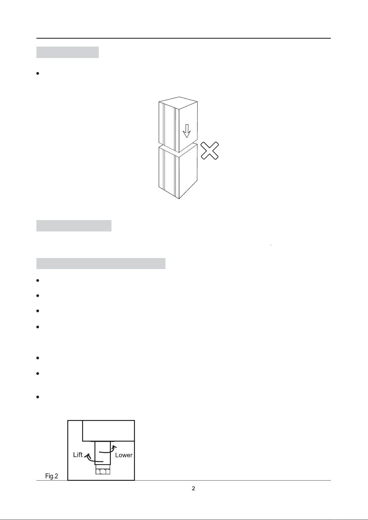
Please keep the unit upright during transportation. Any excessive tip or lean may cause damage to the
unit internally.
If the machine is not upright during transportation, you must leave the unit without powering on to sit for
24 hours before turning the unit on.
1.WARNING
2.INSTALLATION

2.3 Unpacking
Please remove all packaging materials including the protective lm on the stainless steel.
2.4 Refrigerator Installation
The unit must not be double stacked. (Fig.1)
Fig.1
Do not install the machine in the area where it can be damaged by water.
This unit is intended for indoor use only.
Place machine on a at and sturdy surface.
For good ventilation, keep a distance of 100mm between unit and wall or other objects. Increase the distance if
the objects are a near a heating source. When the display is in place, press the brake on the wheels to keep it
level and secure.
Please do not leave stock on the oor of the unit. All stock must be up on a shelf for good ventilation.
For adjustment of refrigerator supporting legs, please refer to the following gure, with max. Adjusting amount of
200mm.
Height adjustment: Clockwise rotate the legs to lift and counter clockwise rotate them to lower.
2.2 Storage

Fig.3
Fig.4
Place the GN pan into the refrigerator.
Fig.5
2.5 Shelf Installation
Once unpacked and all packaging removed.
Ensure that all backing strips are mounted at the same horizontal place with the supporting strips, and they can
be positioned according to the number on the supporting strips.
Remove the shelf backing strips from the plastic belt. For installation, closed end shall be located at rear and open
end at front.
①First push the backing strip backwards to make its rear buckle on the rear supporting strip.
②Lift the front end of backing strip slightly and then buckle it on the front supporting strip. downwards.
Slide the shelves into the refrigerator.

In order to ensure cold air circulation, do not place the foods against the inner wall of refrigerator.
Please do not place foods excess the load line and place foods evenly. The load capacity of each shelf
is 30kgs.
In order to ensure well cold air circulation, do not place the foods against the inner wall of refrigerator.
2.6 Place food
Please do not place foods excess the load line and place foods evenly. The load capacity of each shelf
is 30kgs. (Fig. 11)

Recommend: Before storing any food, it is recommended that refrigerator compressor shall be running
until the unit gets to temperature. During this compressor running period, you can check the power wire
connection.
3.1 Upright Chiller & Freezer
Functions description of keys under normal working condition:
2.7 Power Connection
Do not cut off or remove three-pin plug.
Plug unit directly into socket and not through an extension cord.
In case of failure of power supply, please restart the compressor after ve minutes to prevent damage.
Any damage of compressor due to low voltage will not be included within the warranty range.
3. OPERATION
Startup: Press the power switch button for 3s.
Shutdown: Press the power switch button for 3s.
Set Temp: Press for 3s, the set ting temp. ashing,
and then press or to adjust the temperature.
After without pressed any key for 6s, it will return to
display working temp. display.
In case demisting function is default as “off”, if you need
to turn on the demisting, you need to change the default
demisting setting rst..
Manual defrosting: Press for 3s, then shows and enters the defrosting model. Press
for 3s again to exit.
Its factory default value of controlling temperature is -2°C.

In order to ensure the cooling effect of refrigerator, condenser must be regularly cleaned to prevent
dust or grease accumulation, at least monthly, a dust pan brush can be used to remove dust etc.
In order to ensure good sealing of refrigerator, door seals shall be often cleaned. We recommend
cleaning with warm soapy water at least monthly.
4. CLEANING
4.1 Interior and Exterior Cleaning
4.2 Condenser Cleaning
4.3 Door Seals Cleaning
5. DISPOSAL
Before cleaning, please turn unit off.
Use warm soapy water is used to clean (do not use ammable or toxic substance for cleaning).
During cleaning process, wring dry the cloth to prevent water from owing into the electric component
to cause short circuit.
Render old machine unusable:
1. Pull out the mains plug,
2. Cut off the power cable and discard with the plug,
Caution:
Refrigerants in refrigeration machines and gases in thermal insulation must be disposed of
professionally. Please discard the machine according to the local regulations.

6. TECHNICAL SPECIFICATIONS

7. TROUBLE SHOOTING
If found that the refrigerator can not work normally, please nd out the cause according to the
following table.
Failure !!! Cause !!! Solution
Poor cooling effect
Poor ventilation Check whether the mounting
position is well ventilated
Condenser is blocked Clean the condenser lter
Internally fridge temperature is high
Check stock placement.
Call service agent.
Evaporator is icy
Manually defrost unit
Call service agent.
Temperature incorrect Call service agent.
Ambient temperature is too hot Improve the ventilation and
ambient environment
No power Power surge or failure Call service agent.
Noisy
Loud fan noise/ whistle noise Call service agent.
Check if there is a build up of ice
Defrost manually
Call service agent.
Check whether there are impurities
entering into the condenser lter
Check the condenser and
clean the lter
Alarm
Display SO or SC, with “beeps” buzzing
sound issued
Cabinet temperature sensor
failed
Display ER1, with “beeps” buzzing sound
issued Evaporator liquid inlet sensor
Display ER2, with “beeps” buzzing sound
issued Evaporator suction inlet sensor
Display ER3, with “beeps” buzzing sound
issued
Evaporator temperature inlet
sensor
Display ER4, with “beeps” buzzing sound
issued
Door can not be closed tightly
within 3 minutes or door open
circuit was damaged

8. WIRING DIAGRAMS

1. Castor
2. Castor
3. Door hinge
4. Door hinge
5. Ladder
6. Right supporter
7. Left supporter
8. Shelf
9. Automatic door hinge
10. Complete sets of right door
11. Door gasket
12. Bottom decoration panel
9. PARTS DIAGRAMS
13. Safety lock
14. Magnetic switch
15. Front panel of cooling unit
16. Sticker
17. Control panel
18. LCD screen
19. Condenser lter
20. condenser
21. Controller
22. Blade of evaporator
23. Evaporator fan motor
24. Fan stand
25. Evaporator
26. Compressor
27. Blade of condenser
28. Fan cover
29. Condenser fan motor
30. Power line
31. Solenoid valve body
32. Solenoid valve body
33. Electronic expansion valve coil
34. Electronic expansion valve body
35. Dry lter

1. Castor
2. Castor
3. Ladder
4. Back ladder
5. Door gasket
6. Door hinge
7. Complete sets of right door
8. Complete sets of left door
9. Bottom decoration panel
10. Safety lock
11. Control panel
12. Shelf
13. Right supporter
14. Left supporter
15. Front panel of cooling unit
16. Condenser lter
17. Controller
18. Condenser
19. Electronic expansion valve coil
20. Solenoid valve body
21. Solenoid valve body
22. Power line
23. Dry lter
24. Electronic expansion valve coil
25. Electronic expansion valve body
26. Evaporator fan motor
27. Blade of condenser
28. Fan cover
29. Compressor
30. Evaporator fan motor
31. Blade of evaporator
32. Evaporator
9. PARTS DIAGRAMS


This manual suits for next models
1
Table of contents