S.E.P. SUPER SMART User manual
SUPER SMART
SUPER SMART Diesel
®
USE AND MAINTENANCE MANUAL
GB


GB
REVERSIBLE TWO-WHEEL TRACTOR
SUPER SMART SUPER SMART Diesel
BEFORE USING THE TWO-WHEEL TRACTOR
CAREFULLY READ THE INSTRUCTIONS
GIVEN IN THIS MANUAL

GB
2
TABLE OF CONTENTS
Page Page
INTRODUCTION.................................................... 3
SAFETY REGULATIONS ....................................... 3
GENERAL NOTICES............................................. 3
STARTING THE ENGINE ...................................... 4
OPERATING OF THE TWO-WHEEL TRACTOR ... 4
OPERATING OF ATTACHMENTS ........................ 4
MAINTENANCE..................................................... 4
IDENTIFICATION DATA ........................................ 5
TWO-WHEEL TRACTOR IDENTIFICATION .......... 5
ENGINE IDENTIFICATION.................................... 5
EC MARKING ........................................................ 5
TECHNICAL SPECIFICATIONS............................ 7
ENGINE.................................................................. 7
STARTING............................................................. 7
CLUTCH................................................................ 7
SPEEDS ................................................................ 7
POWER TAKE OFF (PTO) .................................... 7
COUPLING OF ATTACHMENTS .......................... 7
HANDLEBARS ...................................................... 7
WHEELS/TIRES .................................................... 7
ACCESSORIES..................................................... 7
MASS .................................................................... 7
DIMENSIONS........................................................ 7
SAFETY DEVICES ................................................. 8
REVERSE SPEED SAFETY DEVICE..................... 8
TRANSFER PRINTING - INSTRUCTIONS AND
SAFETY.................................................................. 9
TWO-WHEEL TRACTOR CONTROLS .................. 10
OPERATING THE CONTROLS ............................. 10
CONTROLS OF FRONT-MOUNTED ATTACH-
MENTS.................................................................. 11
OPERATING THE TWO-WHEEL TRACTOR.......... 12
STARTING THE ENGINE...................................... 12
STOPPING THE ENGINE..................................... 12
FITTING FRONT-MOUNTED
ATTACHMENTS ..................................................... 13
SAFETY DEVICE .................................................. 13
REVERSING THE HANDLEBARS ........................ 13
REVERSING THE WHEELS ................................. 13
COUPLING ATTACHMENTS TO
THE PTO................................................................. 14
MAINTENANCE...................................................... 14
ENGINE ................................................................ 14
GEARBOX ............................................................ 14
POWER TAKE OFF .............................................. 14
CHECKS AND ADJUSTMENTS............................. 15
CLUTCH LEVER ................................................... 15
ROTARY TILLER .................................................... 16
GENERAL............................................................. 16
ROTARY TILLER TECHNICAL
SPECIFICATIONS ................................................ 16
USING THE ROTARY TILLER............................... 16
ROTARY TILLER ADJUSTMENT .......................... 16
ROTARY TILLER MAINTENANCE ........................ 18
CUTTER BAR MOWER .......................................... 19
GENERAL............................................................. 19
CUTTER BAR MOWER TECHNICAL SPECIFICA-
TIONS................................................................... 20
OPERATING CUTTER BAR MOWERS................. 20
CUTTER BAR MOWER ADJUSTMENT................ 20
CUTTER BAR MOWER MAINTENANCE .............. 21
EC CERTIFICATE OF CONFORMITY
3
INTRODUCTION
• This manual provides Use and Maintenance in-
structions, technical specifications, and safety pre-
cautions for reversible two-wheel tractor:
− model SUPER SMART
in the versions with gasoline engine.
• The first section of this manual provides technical
specifications and gives instructions relevant to
the machine. The second section of the manual
gives further details on individual attachments,
and provides all specific operating instructions.
• Read this USE and MAINTENANCE Manual care-
fully before using your new two-wheel tractor. This
manual provides the most up-to-date information
on your two-wheel tractor available at the time of
going to press. Manufacturer reserves the right to
modify this document at any time without prior no-
tice.
• AFTER-SALES SERVICE. Use only original spare
parts. The use of non-original parts voids the war-
ranty. When ordering spare parts, specify:
− two-wheel tractor serial number;
− part code of spare part required;
− quantity or number of parts required.
SAFETY REGULATIONS
GENERAL NOTICES
Any engine driven machine can become dangerous if
used incorrectly. Pay particular attention to the in-
structions in this manual marked:
WARNING
This symbol means that failure to observe the regula-
tion could cause injury or even death to the operator.
PRUDENCE
Prudence is the Golden Rule to prevent accidents.
TRAINING
The two-wheel tractor must only be used by respon-
sible people trained in the use of the machine and
duly authorized to use it.
MACHINE AND
ENGINE MANUALS
Read those MANUALS carefully before starting, us-
ing, servicing, refuelling or carrying out any work on
the two-wheel tractor.
DECALS
Read all the decals attached to the two-wheel tractor
and follow their prescriptions before starting, driving,
refuelling or servicing the machine. Replace immedi-
ately any damaged or illegible decals.
SUITABLE CLOTHING
• Do not wear wide and flapping clothes that could
be caught in moving parts.
• Always wear robust gloves when servicing the
two-wheel tractor or coupling attachments.
• Do not operate your two-wheel tractor barefoot,
wearing sandals or shorts. Wear heavy shoes and
trousers.
PHYSICAL CONDITION
Do not drive the two-wheel tractor if your physical
condition is not suitable.
NOISE
In order to reduce the problems deriving from the
noise of the machine:
• Do not work with the engine at maximum RPM
range.
• Keep the blade head and the blade holder ad-
justed.
• When using the machine for a long time, use ear
protections.
ENGINE RPM
Do not change the injection system in an attempt of
increase max. engine Rpm.
FIRST AID
It is good operating practice to have a first aid box on
the two-wheel tractor.
SAFETY DEVICES
• Do not use the two-wheel tractor if the safety de-
vices are missing or defective..
• Do not interfere with safety devices.

4
STARTING THE ENGINE
•Disengage all control levers before starting the mo-
tor. Keep your feet clear of the attachments fitted to
the two-wheel tractor.
•Do not run the engine in a closed ambient where
the exhaust gases can collect. They contain car-
bon monoxide that is highly toxic.
•Do not interfere with safety device (engine shut-
off). Do not use the two-wheel tractor if this safety
device is missing or defective.
OPERATING OF THE
TWO-WHEEL TRACTOR
•Make sure that you know how to stop the engine in
an emergency. Familiarize yourself with the con-
trols and learn how to use your two-wheel tractor
correctly.
•Do not allow children or inexperienced people to
operate it.
•Do not use your two-wheel tractor in proximity of
other people, and in particular of children. Do not
use it close to animals. Bear in mind that you are
responsible for any damage or injury caused to
people or things.
•Do not use the rotary tiller attachment without its
protection hood and guards.
•Use your two-wheel tractor only in daylight or with
good artificial lighting. Operate it at walking pace.
Do not run.
•Take particular care on slopes; operate only under
safe and stable conditions. Do not work uphill or
downhill; move across the slope instead. Take spe-
cial care when turning.
•For obvious reasons, never work on slopes steeper
than 30°.
•To ensure that gasoline fuelled engines are cor-
rectly lubricated, avoid working for long periods on
slopes steeper than 20°.
•Do not operate the two-wheel tractor if hoods or
other safety devices are missing or defective.
•Keep your hands and feet clear of all attachments.
•Do not lift or transport your two-wheel tractor with
the engine running.
•Inspect the ground before you start working. Clear
it from stones, wood, wires and any other foreign
objects.
OPERATING OF ATTACHMENTS
•Check that the attachment coupled to the PTO
functions correctly before starting the motor.
•Never use attachments coupled to the PTO in prox-
imity of children or animals.
•Keep your hands and feet well clear of the attach-
ment coupled to the PTO.
•Before using an attachment, make sure that the
reverse speed safety device has been set as re-
quired (this can be used when the front-mounted
attachments are fitted, and not when the tiller is ro-
tating).
•When a front-mounted attachment is installed, the
handlebars are rotated through 180°, hence the
gear and PTO levers are reversed.
•The manufacturer waives any responsibility arising
from improper use of the safety device.
Maximum
Recommended
20°
OK
45°
MF2037-2
MAINTENANCE
•Stop the engine and disconnect the spark plug
lead:
−before checking or repairing your two-wheel
tractor;
−in case of excessive vibrations (investigate
cause immediately).
•Stop the engine before leaving your two-wheel
tractor or adjusting attachments.
•Periodically check that all nuts and bolts are tight.
•Do not leave your two-wheel tractor in closed am-
bients with fuel in the tank. Fuel vapor is a potential
source of danger.

5
•Keep your two-wheel tractor clean. Do not let grass
and oil residues build up: these are a fire hazard.
•Fuel is highly flammable. Store fuel only in spe-
cifically designed containers. Refuel your two-
wheel tractor in the open. Do not smoke while re-
fuelling.
•Complete refuelling before starting the engine. Do
not remove the fuel cap or refuel when the engine
is running or hot. In case of fuel spillage, do not
start the engine. Push your two-wheel tractor some
distance away from where the spillage occurred
before starting it.
•Replace the exhaust pipe if it becomes worn or
damaged.
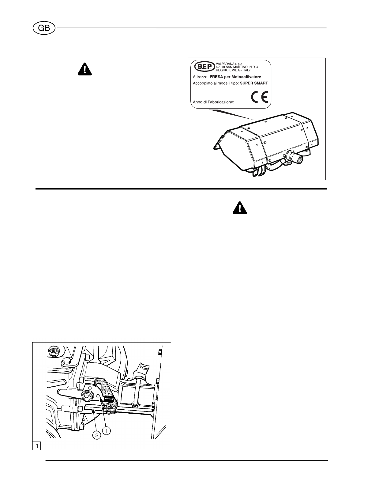
EC MARKING
The two-wheel tractor is marked EC in compliance
with the Directive of the European Community Coun-
cil 89/392/EEC and further amendments (see fig. 1,
part 2).
The summary of the EC marking related to the SU-
PER SMART model is indicated below.
IDENTIFICATION DATA
TWO-WHEEL TRACTOR IDENTIFICATION
The serial number is stamped on the engine side of
the gear box of your two-wheel tractor (see fig. 1, item
1).
ENGINE IDENTIFICATION
Refer to the engine Operation and Maintenance Man-
ual.

6
Modello tipo:
N. Serie:
Mot.:
Potenza: kW/ rpm
Anno di Fabbricazione:
Massa: kg
SUPER SMART
LGA 226
4 3600
70,000
BH10X00000
Engine:
LOMBARDINI LGA 226
cm. 50
Mass (weight):
with wheels 3.50-6
with rotary tiller
83,5
81,5
<2,5
Test conditions
- P.T.O.: Disengaged - machinestationary on a
concrete plane surface
Test conditions:
- P.T.O.: Engaged
Sound
pressure on
operator’s ears
dB(A)
Sound
pressure on
operator’s ears
dB(A)
(Macchine
stationary
on a grass
surface)
(Macchine
stationary on a
concrete surface
with an interposed
elastic layer)
(Machine
running on a
concrete surface
with an interposed
elastic layer)
Acoustic power
dB(A)
Acoustic power
dB(A)
Acceleration
on hangrip
EN 1033 - 28662/1
m/sec
2
Acceleration
on hangrip
EN 1033 - 28662/1
m/sec
2
<2,5
89
87,5
104,5
102,5
11,75
11,75
With SICKLE BAR MOWER cm. 96
NOISE AND VIBRATIONS
TYPE OF MARKING
TWO-WHEEL TRACTOR
SUPER SMART - SUPER SMART Diesel
Models:
to
(punched on the gearbox)
SUPER SMART - SUPER SMART Diesel
A211408 A212096Progressiv unit number starting from
Progressiv unit number starting from AC00001
With SICKLE BAR MOWER cm. 96
With ROTARY TILLER cm. 50
With ROTARY TILLER cm. 50
-
-
Engine:
Mass (weight):
with wheels 3.50-6
with rotary tiller
HONDA GC 160
a cm. 50
Modello tipo:
N. Serie:
Mot.:
Potenza: 3,7 kW/ rpm
Anno di Fabbricazione:
Massa: kg
SUPER SMART
GC 160
3600
66,500
BH10X00000
87,5 6,1 NO NO
See NOTEWith ROTARY TILLER cm. 50
100 NO
Engine:
YANMAR L48
cm. 50
Mass (weight):
with wheels 3.50-6
with rotary tiller
Modello tipo:
N. Serie:
Mot.:
Potenza: kW/ rpm
Anno di Fabbricazione:
Massa: kg
SUPER SMART Diesel
L48
3,4 3600
83,500
BH10X00000
TR1017-4GB
NOTE: SUPER SMART Diesel model does not allow the use of front attachment.
VALPADANA
42018 SAN MARTINO IN RIO
REGGIO EMILIA - ITALY
S.p.A.
VALPADANA
42018 SAN MARTINO IN RIO
REGGIO EMILIA - ITALY
S.p.A.
VALPADANA
42018 SAN MARTINO IN RIO
REGGIO EMILIA - ITALY
S.p.A.
S/N reading: type of machine
year of manufacturing
000 week of production
00 progressiv n° of production
X
00
000
BH10
GB

7
TECHNICAL SPECIFICATIONS
ENGINE
The two-wheel tractor may be fitted with the following
engines:
−HONDA GC 160; 4 stroke gasoline engine;
3,7 kW (5 CV); 160 cm3.
−LOMBARDINI LGA 226; 4 stroke gasoline engine;
4 kW (5,4 CV); 220 cm3.
−YANMAR L48; 4 stroke Diesel engine;
4 kW (5,4 CV); 212 cm3.
STARTING
Rewind start.
CLUTCH
Cone clutch, oil immersed with control lever.
SPEEDS
MAX SPEED (km/h)
POWER TAKE OFF (PTO)
Mounted attachments are driven via an independent,
single speed PTO engaged by a control lever on the
handlebars.
Maximum PTO speed: 923 rpm (clockwise rotation).
COUPLING OF ATTACHMENTS
Coupling of attachments to the PTO is obtained
through a quick change fitting that provides for fast
installation of the attachments, and does not require
the use of bolts, nuts or spanner.
HANDLEBARS
Adjustable in height and width. Rotate handlebars
through 180 when front-mounted attachments are
used.
WHEELS/TYRES
−Pneumatic tyres with agricultural tread.
−Available sizes: 3.50-6.
−Inflation pressure: 1.2 bar.
NOTE
The instructions covering track adjustment, based on
motor-mower model and type of wheel, are given in a
specific paragraph in this manual
ACCESSORIES
The two-wheel tractor can be fitted with a wide range
of additional easy-to-fit accessories. These are, for in-
stance, several types of iron wheels, watering pumps
and sprayers, snowploughs, ploughs, trailers, water
sprinkling trolleys, etc.
Refer to our catalogue for details about the various
accessories available.
MASS
Refer to the identification plate installed on the ma-
chine.
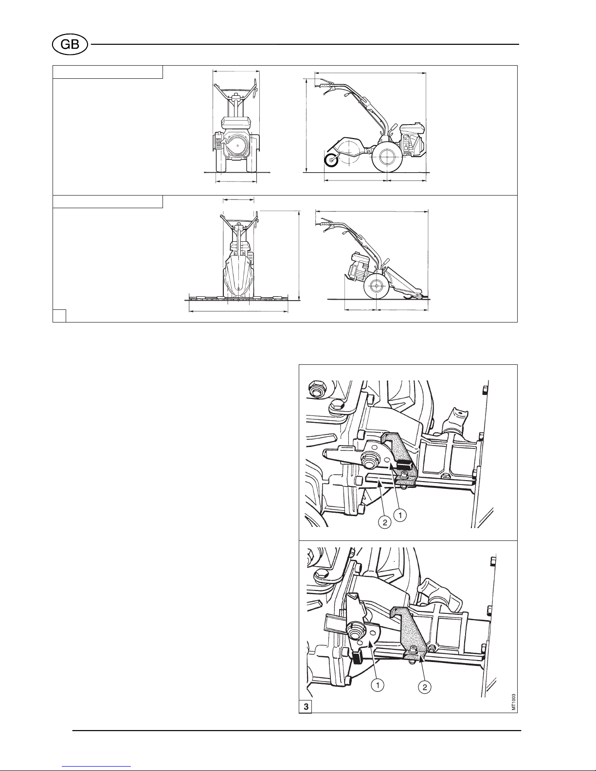
DIMENSIONS
The overall dimensions of the two-wheel tractor are
shown in fig.2.
8
2
MT1002-1GB
MOTOR-MOWER
TWO-WHEEL TRACTOR
490 1450
680
370 ÷ 400
950 ÷ 960 460 670
1500
830 ÷ 960 820 ÷ 1080
470
370 ÷ 400
SAFETY DEVICES
The two-wheel tractor is fitted with the following safety
devices to ensure maximum safety:
−Automatic PTO disengagement device. This is a
mechanical device that prevents shift into reverse
speed when the PTO is rotating (motor-mower
configuration only).
−Engine shut-off. This is an electrical device which
stops the engine as soon as the handlebars are
released (see fig. 4, item 2).
REVERSE SPEED SAFETY DEVICE
The two-wheel tractor is provided with an operator-
adjusted safety device (see fig. 3, item 1) that pre-
vents concurrent use of reverse speed and attach-
ment when the rotary tiller is fitted.
To use reverse gear it is necessary first to disengage
the power take-off control lever and then engage the
gear lever.
When installing the rotary tiller, check that the small
lever (1) is in the two-wheel tractor position; if not, the
pin (2) prevent complete engagement of the rotary
tiller at the linkage.
NOTE
Reverse gear cannot be engaged while the tines of
the rotary tiller are rotating.

9
TRANSFER PRINTING -
INSTRUCTIONS AND SAFETY
Please find below the adhesive transfer printing
shown on the machine.
For accident prevention purposes, they must always
be clearly readable. Should they be damaged, it is
compulsory to replace them by requesting the origi-
nal spare part from the Manufacturer.

10
TWO-WHEEL TRACTOR CONTROLS
See fig.4.
1. Clutch lever.
2. Engine stop lever.
3. Gear lever. (Note 2)
4. Handlebar vertical lock release lever.
5. Handlebar sideway lock release lever.
6. PTO control lever. (Note 1).
7. Throttle control lever.
8. Attachments instant adaptor.
NOTE 1: When the machine is fitted with front-
mounted attachments, this lever becomes
the gear lever.
NOTE 2: When the machine is fitted with front-
mounted attachments, this lever becomes
the PTO control lever.
OPERATING THE CONTROLS
Clutch lever
(See fig. 5)
− Lever (1) pulled up: clutch disengaged.
− Lever (1) released: clutch engaged.
Engine stop lever
See figure 5.
− Lever (2) pressed down: engine running.
− Lever (2) released: engine stopped.
Throttle control lever
(See figure 5)
− Lever (3) in up position: engine at idle.
− Lever (3) in down position: max engine rpm.
Gear lever (two-wheel tractor configuration)
CAUTION
When using the machine as a motor mower, the han-
dlebars must be rotated through 180. The gear and
PTO control levers therefore interchange position.
See page 11 for details.
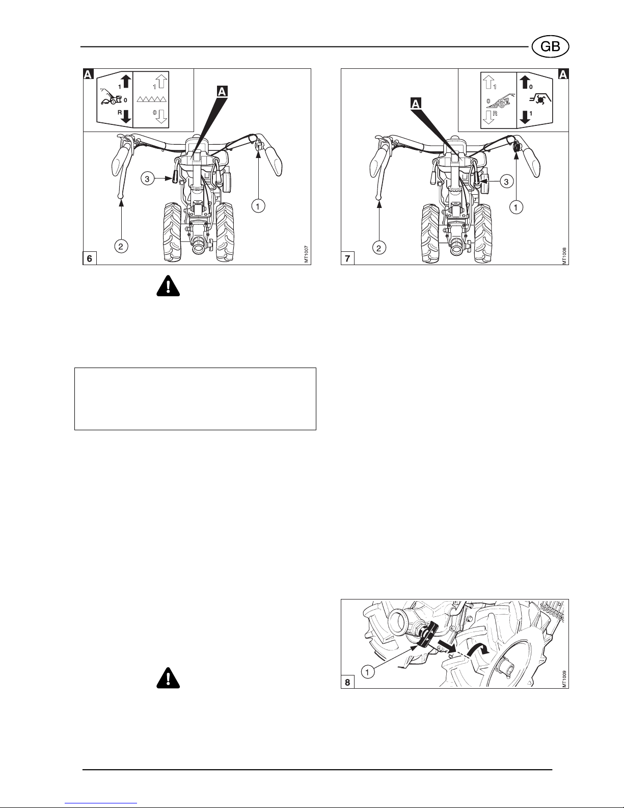
Use the gear lever as shown below (see fig. 6):
a. Turn the throttle control lever (1) to idle position.
b. Pull up clutch lever (2).
c. Move the gear lever (refer to fig. 6, item 3) to the
required position (see the plate illustrated in detail
A), and release it as soon as the gear is engaged.
d. Gradually release the clutch lever while accelerat-
ing the engine.
e. To disengage gear, pull up the clutch lever (2) and
move gear lever (3) to the neutral position.
11
WARNING
A safety device does not permit reverse speed to be
engaged when the PTO is operating (rotary tilling)
Power Take Off (PTO) control lever (two-
wheel tractor configuration)
CAUTION
When using the machine as a motor mower, the han-
dlebars must be rotated through 180. The gear selec-
tor and PTO control levers therefore interchange posi-
tion. See page 12 for details
The Power Take Off (PTO) control lever engages the
drive to the attachment.
To engage and disengage drive, proceed as follows
(see fig. 7):
a. Turn throttle lever (1) to idle position.
b. Pull up clutch lever (2).
c. Pull PTO control lever (3) and release it when drive
is engaged (see plate in detail A.)
The lever (3) has two positions:
− 1: power take-off operating.
− 0: power take-off stopped.
d. Release the clutch lever while accelerating the en-
gine.
CAUTION
The clutch lever must be released slowly to prevent
damage to the drive. Do not start working with at-
tachment loaded (into the soil).
WARNING
A safety device prevents you from using the rotary til-
ler attachment in reverse gear. Do not use the two-
wheel tractor if this safety device is not correctly in-
stalled.
Handlebar vertical lock release lever
(See fig. 4, item 4)
This allows the handle to be vertically adjusted to suit
driving comfort and tilling depth.
Simply push down lever (1) to release handles.
Handlebar sideway lock release lever
(See fig. 4, item 5)
By releasing lock lever (5), you may rotate the han-
dlebars for the use of front mounted attachments.
PTO Instant adaptor
This allows attachments to be coupled and de-
coupled quickly and easily to and from the PTO. The
lever (fig. 8, item 1) has two positions.
− Free position: pull the lever (1) outwards and lock
in this position by turning it 90°.
− Locked position: turn the lever (1) 90°; if the cou-
pling with the attachment is correct, the lever will
automatically return to its original position, thereby
locking the attachment.
See page 13 for instructions on how to fit the attach-
ments.
CONTROLS OF FRONT-MOUNTED
ATTACHMENTS
When the machine is used with front-mounted at-
tachments, the gear and the PTO levers are reversed

12
with respect to when the machine is used as a motor-
mower.
This is due to reversal of the direction of motion.
Lever (fig. 9, item 1) becomes the gear lever, and
lever (2) becomes the PTO control lever. The symbols
shown in figure 9 and applied to the column, remind
the user about the functions of the levers.
OPERATING THE
TWO-WHEEL TRACTOR
WARNING
Before operating your reversible two-wheel tractor,
read carefully and commit to memory the instructions
given in the GENERAL SAFETY PRECAUTIONS para-
graph at the beginning of this manual.
STARTING THE ENGINE
NOTE
See the engine Operating and Maintenance manual
for all information regarding the engine.
a. Disengage all control levers before starting the
engine
b. Open the fuel cock.
c. Position the small starter lever.
The position of the starter, for starting with a cold
engine, is shown on the appropriate plate. When
starting with a hot engine, the starter lever must be
kept in in-gear position.
d. Press down the engine stop lever (fig. 10, item 1).
e. Pull clutch lever (2) fully up.
f. Lock the clutch lever (1) in down position with
locking device (3).
g. Turn throttle lever (4) for 1/4 turn.
h. Grip the pull-rope handle and pull firmly and
quickly. When the engine starts, allow the rope to
wind back onto the reel slowly.
i. Turn the throttle lever (4) to idle position, and allow
the engine to warm up.
NOTE
Do not leave the clutch lever pulled up for an ex-
tended length of time after the engine has started.
This could cause damage to the clutch.
STOPPING THE ENGINE
a. Turn throttle lever (fig. 11, item 1) to idle position.
b. Release the engine stop lever (2).
c. If you plan not to use your two-wheel tractor for a
long time, shut off the fuel cock (if installed).
WARNING
The engine stop lever (2) also operates as a safety
device (emergency stop), and stops the engine as
soon as it is released.
13
FITTING FRONT-MOUNTED
ATTACHMENTS
Before fitting a front-mounted attachment (cutter bar
mower, rotary mower, snow thrower, etc.), adjust the
reverse speed safety device as required, reverse the
handlebars and the wheels.
CAUTION
SUPER SMART Diesel model does not allow the use
of front attachment.
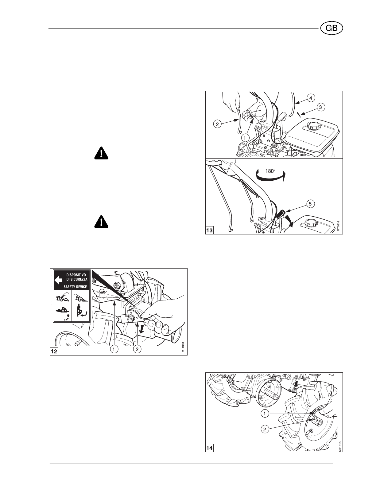
SAFETY DEVICE
Set the reverse speed safety device in the correct po-
sition as regards the direction of travel (see fig. 12).
WARNING
Before using the machine, check that is in correct po-
sition.
a. Move the lever (1) to give free movement of the
safety device.
b. Push the safety device lever (2) down (see the
plate showing the "motor mower") to allow reverse
gear to be engaged.
WARNING
When converting the machine back into the two-
wheel tractor version, to fit the rotary tiller, engage the
safety device by proceeding in the opposite way to
the way described above (see the plate showing the
"two-wheel tractor”).
REVERSING THE HANDLEBARS
Rotate the handlebars through 180° to operate the
machine in the changed direction of motion. Proceed
as follows:
a. Remove the pin (see fig. 13, item 1) locking the
gear control rod (2).
b. Remove the pin (3) locking the power take-off rod
(4).
c. Squeeze the lever (5) and rotate the handlebars,
180° anticlockwise; release the lever (5) and lock
the handlebars.
d. Connect again the gear (2) and PTO (4) control
rods to the corresponding control levers and se-
cure with pins (1) and (2).
NOTE
While reversing the handlebars, make sure that the
cables do not become tangled or caught.
REVERSING THE WHEELS
Every time you use a front-mounted attachment, the
wheels must be interchanged to keep the tread pat-
tern pointing in the right direction. Simply remove
each wheel from its hub and install it on the opposite
hub. An arrow on the sidewall of the tire indicates the
correct direction of rotation (see fig. 14).
a. Remove the pins (1).
b. Remove the wheels and put the right wheel on the
left and vice-versa.
c. Replace the pins (1).
Adjusting the track
Two different track sizes can be obtained as a result
of the double holes in the hub cap (2). To do this, fix
the wheel by means of the plug (1), which is inserted
into the desired hole.

14
COUPLING ATTACHMENTS TO
THE PTO
The PTO is fitted with an instant adaptor device to fit
attachments quickly and easily. Proceed as follows to
fit your attachments (see fig. 15):
a. Check that lever (1) is in disengaged position.
b. Push the shaft of the attachment into the PTO (2).
Make sure that it engages fully.
c. Rotate lever (1) clockwise to the engaged position.
Check that the attachment is correctly locked.
MAINTENANCE
To ensure continuing reliability, use only original
spare parts when overhauling or repairing your two-
wheel tractor.
ENGINE
Make sure you do comply with the safety precautions
contained in the engine Operation and Maintenance
Manual.
GEARBOX
After the first 50 hours (running in)
Change the oil (see fig. 16). Change the oil when the
engine is hot to facilitate draining of oil.
a. Remove the right wheel.
b. Remove the oil dip-stick (1).
c. Remove the oil drain plug (3) from the bottom of
the gearbox (right side) and let the oil drain out.
When fully drained, reinstall the plug (3).
d. Fill up with new oil (1.3 l) of the following types:
− SAE 90 for ambient temperatures between
-6 and +32°C;
− SAE 140 for ambient temperatures between
+32 and +60°C.
Every 20 hours
Check the oil level in the gearbox housing: to do this,
slacken the screw (2) and check that oil is coming out
from the screw position.
NOTE
Check the oil level with the motor cold and with the
two-wheel tractor on level ground.
Every 300 hours
Change the gearbox oil following the instructions
given in the above paragraph covering running in.
POWER TAKE OFF
Every 8 hours
Grease the PTO (see fig. 17, item 1).
Also grease the PTO every time you fit a new attach-
ment.

15
CHECKS AND ADJUSTMENTS
CLUTCH LEVER
The clutch lever must have a free play of about 5 to 6
mm before the clutch starts to disengage.
Insufficient play can cause clutch slip, while excess
play can lead to failure to disengage fully.
Adjust play by means of cable adjuster (see fig. 18,
item 1).
16
ROTARY TILLER
WARNING
• Do not use the rotary tiller without the hood.
• Do not proceed to tilling in proximity of children
and/or animals.
• Keep your hands and feet clear of the tiller at-
tachment when the motor is running. Stop the en-
gine before touching the tiller for any reason.
• Make sure that the reverse speed safety device is
installed correctly, via as described on page 12.
GENERAL
The rotary tiller is used to till gardens, orchards and
vineyards, to prepare seed beds and to break up ag-
ricultural ground in general.
Various sizes of rotary tiller can be fitted, from 40 to
50 cm.
Rotary tillers are fitted with hoods and side guards.
Hoods can be fixed or adjustable according to the
model. A wheel is also provided for easy transport of
the two-wheel tractor with the tiller attachment fitted.
ROTARY TILLER TECHNICAL
SPECIFICATIONS
− Transmission: bevel gears in oil bath.
− Max. rotation speed: 300 rpm.
− Working width: 40 to 50 cm, adjustable.
− Weight: 20,700 kg.
WARNING
The rotary tiller is provided with a safety device, fitted
to the attachment flange (fig. 1, item 2) which pre-
vents attachment installation when the machine is
configured as required for the use of the front-
mounted attachments (small lever (1) in “two-wheel
tractor” position).
USING THE ROTARY TILLER
The rotary tiller is driven via the PTO. Proceed as fol-
lows:
a. Pull up clutch lever and engage first speed with
gear lever.
b. Pull PTO control lever, and release it when drive is
engaged.
c. Slowly release the clutch lever to start tiller rotation
and at the same time accelerate engine speed by
means of throttle.
CAUTION
Release the clutch lever gradually. It is also advisable
to sink the tiller in the soil slowly.
ROTARY TILLER ADJUSTMENT
Tilling width adjustment
The adjustable tiller model allows you to set working
widths of 40 and 50 cm, to suit the type of crop.
Adjustment of tilling width is obtained by reversing
the position of the two pairs of outside tiller rotors of

17
each tilling element, and by removing or adding one
tiller rotor at the end of the two tillers.
Refer to fig. 2 to determine the tiller rotor configura-
tion required to obtain the desired tilling width, then
proceed as follows.
To reverse the position of the outside tiller rotor pairs
(fig. 3, item 1), remove the four attachment nuts (2)
and invert the position of the outside pair of tiller ro-
tors, fitting the left rotor to the right and vice-versa.
Make sure you keep the cutting edge of the rotors
facing the front of the machine.
Adjustment of protection guards
a. Adjust width of protection guards to suit new tilling
width. To do this, remove the screws (fig. 4, item
1), and install the two side extensions (2).
b. Adjust width of matching piece (3) by use of
screws (4).
Tilling depth adjustment
To vary tilling depth you must adjust the height of rear
tine (fig. 5, part. 1). Proceed as follows:
a. Remove nut and bolt (2).
b. Move the tine up or down until the slot on the
bracket corresponds to the desired hole on the
tine shank. Replace nut and bolt (2) and fully
tighten.
Ground adjustment
Adjust the position of the rotary tiller as follows to en-
sure correct movement over different types of ground:
HARD GROUND
If the tiller tends to jump on hard ground, lower the
tine to lift the rotary tiller.
SOFT GROUND
If the tiller tends to sink in on soft ground, lower the
tine to move the centre of gravity over the machine
wheels.
18
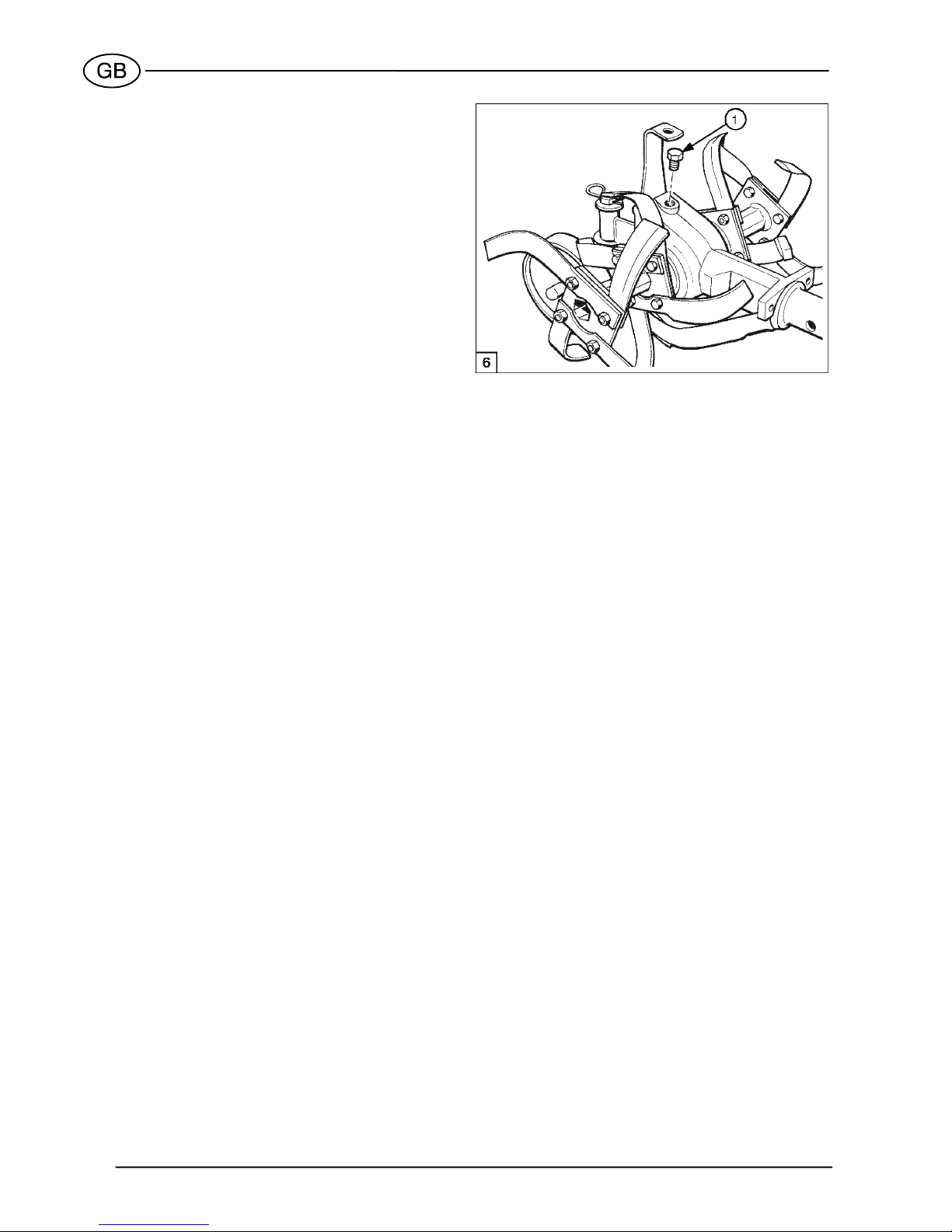
ROTARY TILLER MAINTENANCE
After the first 50 hours (running in)
a. Check that all nuts and bolts are secure. Tighten if
necessary.
b. Change the oil in the tiller drive unit as follows.
Remove plug (fig. 6, item 1) and turn the attach-
ment upside down to drain out the exhausted oil.
Return the attachment to the upright position, and
add 0.3 l of the same oil used for the machine
gearbox. Reinstall plug.
Every 300 hours
Change the tiller drive unit oil as instructed above.
This manual suits for next models
1
Table of contents
Other S.E.P. Lawn Mower manuals
 User manual")
Popular Lawn Mower manuals by other brands


Powersmart
Powersmart PSM2521SH instruction manual

Midwest
Midwest 179-2304 quick start guide

Mac allister
Mac allister MAC1700RMA Safety and operating manual

Powersmart
Powersmart PS2321SR instruction manual

Bad Boy
Bad Boy OUTLAW EXTREME Owner's, service & parts manual

Oleo-Mac
Oleo-Mac APACHE 92 Operators instruction book