SAC SS-800AVS User manual

SOUTHERN A VIQNlC.,q COM.~A NY
MANUFACTURERS OF LOW FREOUENCY RADIOBEACONS AND ASSOCIATED PRODUCTS
MODEL SS-800AVS
NON-DIRECTIONAL RADIOBEACON
MANUAL #80AVS-90-2
BOX 5345, BEAUMONT, TEXAS 77726-5345 USA; TELEPHONE: (409) 842-1717; CABLF" SAC; TELEX: 77-9450: FAX: (409) 842-2987

___~--,-~ E
LIMI~D
ALL IMPLIED WARRANTIZS EXISTING UNDER ~ LAW AItE HY~EBY EXPRESSLY NEGATED;
pARTICOT2L~3IY, COMPANY HEItEBY N~GATES A~D DZSCLAIM~ T~ IMPLIED WARP,~NTY OF
KERCHANTA~ILITY A~D IMPLIED WARRANTY OF FITNESS FOR A PARTICULAR PVRPOSEo
If Purchaser believes that these goods do not comply with the express
warranty stated above or any existing and applicable implied warranty which
under the law canno~ be disclaimed or negated as provided above, then
purchaser may request that COMPAB~ inspec~ such goods by mailing, within
s ix~cy (60) days after purchaser k~ows or should have kno~ ~hat the goods
allegedly do not conform with the warranty, postage prepaid, to ~OM~ANY,
P.O. Box 5345, 5000 Belmont, Beaumont, Texas, 77726 Attention: President,
a writing specifying (a) purchaser’s name, address, and telephone mummer,
(b) date of purchase, (c) COMPANY distributor or location from which the
goods were purchased, (d) location of the goods in question (or include the
goods in question with the notice}, and (e} a brief description of the
alleged nonconformity with the warranty. If the goods are covered by, and
do not conform with, the warranty, COMPANY will repair or replace F.O.B.
point of manufacture any such goods; but in no event will COMPANY be
obligated or required to remove the non-conforming goods from their place
of installation or to install the replacement goods. All replacement goods
are warranted to the e~ent provided herein for the remaining te~ of ~his
warranty.
In the
even~
purchaser chooses to commence an action for breach of warranty
or breach of con~rao~ arising out of the sale of the goods pursuan= to this
invoice, the purchaser must
commence
such action within one year after the
cause of action accrues.
THE
RF--~EDY
PROVIDED
H~BEIN SHALL BE THE SOLE ~
EXCLUSIVEREMEDY
FOR
BREACH OF THIS ~%RP2%NTY, FOR ~ BR~ACR OF ANY IMI~LI~D WA/tR~A~TY EXISTING
AND APPLICABLE UNDER TH~ LAW (TO TH~ EXTENT THAT ANY SUC~ WARRAN~ HAS NOT
BEEN SUCCESSFULLY NEGATED AND DISClAIMeD KEREI~AROVE), AND FOR ~ ACT OF
N~GLIGENCY OR ANY OTHER TORTIOUS ACT COMMITTED BY COMPANY, AND IN NO EVENT
SHALL THE
COMPANY ~E LIARLE TO PURCHASER OR ANY THIRD PAR~"~
FOR
ANY
INCIDENTAL,
CONSEQUENTIAL OR SPECIAL DAMAGES RESULTING FROM ANY DEFECT
IN
THE GOODS OR ~
FAILURE OF TH~ GOODS TO CONFORM WITH THIS WAR/%~ATTY OR
ANY
IMPLIED ~
EXISTING AND APPLICABLE UNDER THE LAW (TO T~E EXTENT
THAT
ANY SUCH IMPLIED
~ HA~ NOT BEEM SUCCESSFULLY NEGATED AND DISCLAIMED
~REINA~OVE ).

Table of Contents
1 INTRODUCTION ...........................................
1
i.I General Description: SS-800AVS .....................
1
1.2 Specifications: SS-800AVS ..........................
3
1.3 General Description: PC-1000B ......................
7
1.4 Specifications: PC-1000B ...........................
9
2 THEORY OF OPERATION, RADIOBEACON .......................
ii
2.1 Functional Description: SS-800AVS ..................
ii
2.2 Detailed Circuit Analysis: SS-800AVS ...............
13
....
2.2.1 Synthesizer PWB: ..............................
13
2.2.2 AM Oscillator PWB .............................
17
2.2.3 Audio PWB (Optional) ..........................
21
2.2.4 Keyer .........................................
25
2.2.4.1 Letter PWB ................................
25
2.2.4.2 Number PWB ................................
26
2.2.4.3 AM Recycle PWB ............................
26
2.2.5 Driver PWB ....................................
35
2.2.6 Final Stage ...................................
39
2.2.7 Power Supply ..........................
; .......
41
2.2.8 Battery System ................................
45
2.2.9 AM Auto Shutdown PWB ..........................
49
2.2.10 Power Switch PWB Assembly ....................
53
2.2.11 Metering Circuit .............................
57
2.2.12 Reset SSC PWB ................................
61
3 THEORY OF OPERATION, ANTENNA COUPLER ...................
69
3.1 FUNCTIONAL DESCRIPTION: PC-1000B ..................
69
3.1.1 Impedance Transformer ~..~ .....................
69
3.1.2 Tuner .........................................
69
3.1.3 Autotune ......................................
69
3.1.4 Antenna Current/Tuning Meter ..................
69
3.2 DETAILED CIRCUIT ANALYSIS: PC-1000B ................
71
3.2.1 Impedance Transformers: .......................
71
3.2.2 Tuner: ........................................
71
3.2.3 Autotune ......................................
73
3.2.4 Antenna Current/Tuning Meter ..................
77
4 ANTENNAS ...............................................
81
4.1 Mast Antenna .......................................
81
4.2 "H" Antenna ........................................
82
4.3 50-Foot Guyed Mast Antenna .........................
82
4.4 Symmetrical "T" Antenna ............................
83
5 INSTALLATION AND OPERATION .............................
85
5.1 Transmitter Installation ...........................
85
5.2 Coupler Setup ......................................
87
SS-800AVS
Southern Avionics
Company
i

5.3 Synthesizer Adjustment .............................
95
5.4 Antenna Tune-Up ....................................
99
5.5 Audio Mode Selection ...............................
103
5.6 Tone Modulation Adjustments ........................
104
5.7 Transmitter Adjustments ............................
105
5.7.1 Autoshutdown and Audio Alignment ..............
105
5.7.2 Autoshutdown Adjustment - Nonvoice System .....
106
5.7.3 Automatic Shutdown Test .......................
106
5.7.4 Final .........................................
107
6 MAINTENANCE ............................................
109
6.1 Cautions and Test Equipment List ...................
109
:~ 6.1.1 General~ Precautions ...........................
109
6.1.2 Specific Precautions ..........................
109
6.1.3 Test Equipment List ...........................
109
6.1.3.1 Field Service or Checkout .................
ii0
6.1.3.2 System Alignment and Calibration ..........
ii0
6.2 System Alignment and Calibration ...................
iii
6.2.1 AM Oscillator PWB .............................
iii
6.2.1.1 Preliminary ...............................
iii
6.2.1.2 Frequency and Modulation Adjustment .......
iii
6.2.2 Audio PWB Adjustment ..........................
112
6.2.3 Antenna System Changes ........................
112
6.2.4 Battery Charger Float Voltage Adjustment ......
113
6.3 Preventive Maintenance .............................
115
6.3.1 Maintenance Log ...............................
115
6.4 Corrective Maintenance .............................
117
6.4.1 Index To Testpoints ...........................
117
7 PARTS LIST .............................................
127
8 MODIFICATIONS ..........................................
163
ii
Southern Avionics SS-800AVS
Company

Table of Figures
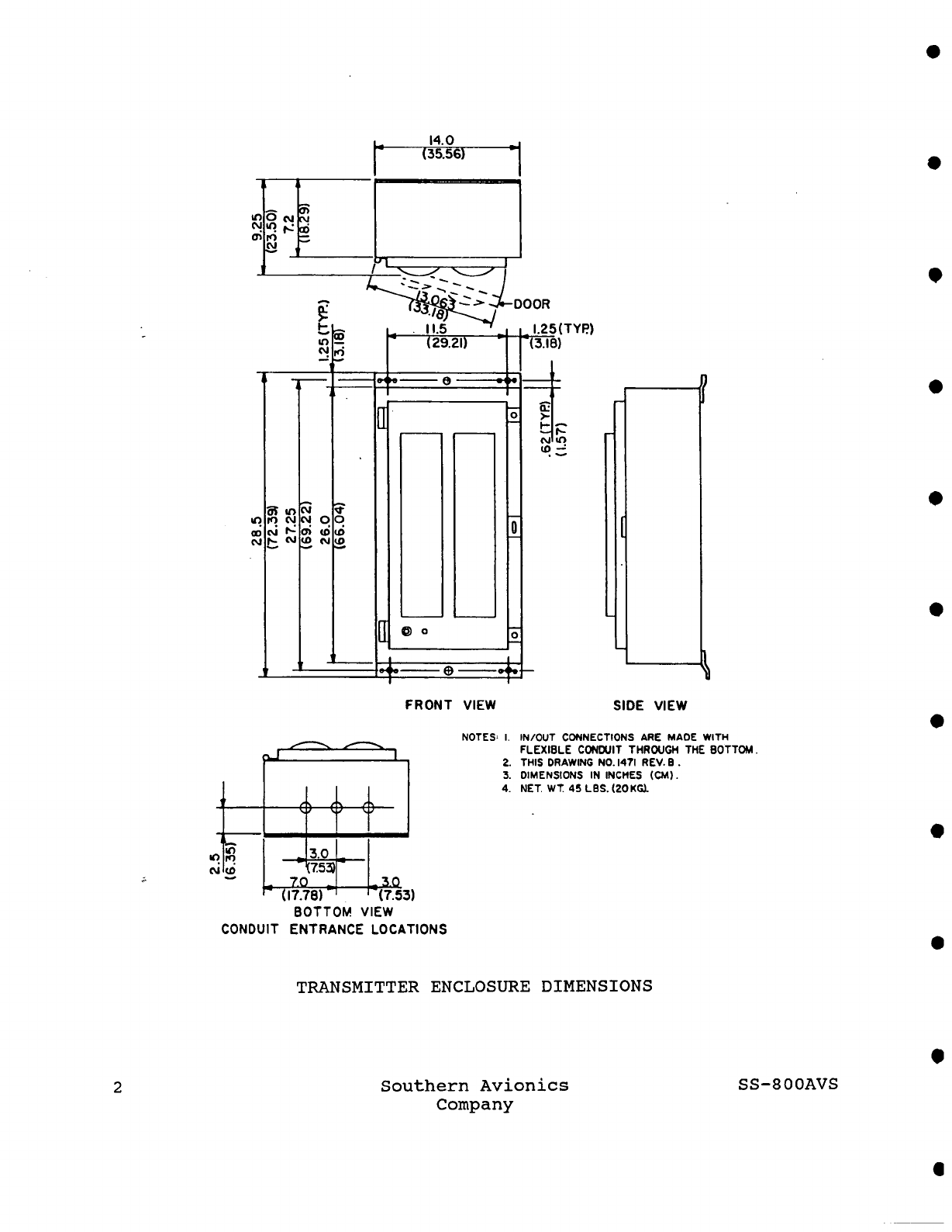
Transmitter Enclosure Dimensions .........................
2
Coupler Enclosure Dimensions .............................
8
Block Diagram ............................................
12
Synthesizer PWB Schematic ................................
14
Synthesizer PWB Assembly ..................................
15
Synthesizer Programming PWB Assembly .....................
16
AM Oscillator PWB Schematic ..............................
18
AM Oscillator PWB Assembly ...............................
19
Audio PWB Schematic ......................................
22
Audio PWB Assembly .......................................
23
Letter PWB Schematic .....................................
29
Letter PWB Assembly ......................................
30
Number PWB Schematic .....................................
31
Number PWB Assembly ......................................
32
AM Recycle PWB Schematic .................................
33
AM Recycle PWB Assembly ..................................
34
Driver PWB Schematic .....................................
36
Driver PWB Assembly ......................................
37
Final Stage Schematic ....................................
40
50 V Power Supply Schematic ..............................
42
50 Volt Power Supply .........................
, ...........
43
SSC Battery Standby Schematic ............................
46
SSC Battery Standby Assembly .............................
47
AM Auto Shutdown PWB Schematic ...........................
50
AM Auto Shutdown PWB Assembly ............................
51
Power Switch PWB Schematic ...............................
54
Power Switch PWB Assembly ................................
55
Meter PWB Schematic ......................................
58
Meter PWB Assembly .......................................
59
Meter Bracket Assembly ...................................
60
Auto Shutdown Reset PWB Schematic ........................
63
Reset SSC PWB Assembly ...................................
64
Transmitter Schematic ....................................
66
Transmitter Diagram ......................................
68
PC-1000 Block Diagram ....................................
70
PC-1000B Antenna Coupler Schematic .......................
72
Autotune Motor Drive PWB Schematic .......................
75
Autotune Motor Drive Pwb Assembly ........................
76
Antenna Current/Tuning Meter Pwb Schhematic ..............
78
Antenna Current/Tuning Meter PWB Assembly ................
79
Antenna Reactance ........................................
84
Antenna Coupler Cable Connections ........................
88
Impedance Transformer Taps ...............................
89
Mast Antenna and PC-1000 Mast Tuned for 190-415 KHz ......
90
Mast Antenna and PC-1000 Mast Tuned for 415-625 KHz ......
91
50 Foot Guyed Mast and PC-1000 ...........................
92
SS-800AVS
Southern Avionics
Company
iii

Symmetrical "T" Antenna and PC-1000 ......................
93
Synthesizer Bands ........................................
97
Control and Testpoin Positions ...........................
98
iv
Southern Avionics SS-800AVS
Company

1 INTRODUCTION
1.1 General Description: SS-800AVS
This non-directional beacon is a dual carrier transmitter with an
adjustable output power of up to i00 watts. This is the power of
a single carrier° The second carrier is added to the first during
modulation. This produces a signal withan AM type waveform and an
SSB bandwidth. The bandwidth of a .dual carrier emission is the
same as the audio tone (either 1020 Hz or 400 Hz).
The transmitter operates on 115/230 VAC, 50/60 Hz or 48 VDC.
An automatic shutdown circuit is included that automatically shuts
down the transmitter if power falls below an adjustable level, if
the ident signal fails, or if extreme distortion is present. When
a dual system is used, the shutdown signal is used to transfer to
the standby transmitter°
A current and voltage limiter protects the transmitter from line
surges or voltage and current surges in the final due to accidental
shorts or improper tuning.
The transmitter is in a rain-tight enclosure that permits it to be
mounted out-of-doors at the base of the antenna.
SS-800AVS
Southern Avionics
Company

14.0
(35.56)
I
~
iOOOR
¯ 11.5
’
I 25(TYP)
FRONT
VIEW SIDE VIEW
7.0 ~I I_ 3.0
~ (17.78)
-~
. ~-(7.5~)
BOTTOM
VIEW
CONDUIT ENTRANCE LOCATIONS
NOTES=
I.
IN/OUT CONNECTIONS ARE MAOE WITH
FLEXIBLE CONI~JI! THROUGH
THE BOTTOM.
2.
THIS DRAWING NO. 1471 REV. B .
3.
DIMENSIONS IN INCHES (CM).
4l
NET. wT. 4SLBS.(2OKGL
TRANSMITTER ENCLOSURE DIMENSIONS
Southern Avionics
Company
SS-800AVS

1.2 Specifications: SS-800AVS
QUALIFICATIONS: Meets applicable requirements of the Federal
Aviation Administration (FAA), Federal Communications Commission
(FCC), and International Civil Aviation Organization (ICAO).
FREQUENCY: 190-625 KHz.
FREQUENCY CONTROL AND STABILITY: Crystal controlled synthesizer.
Rotary dial selection in KHz steps, at integral or half integral
KHz; stability better than 0.005% (-50° to +70°C). Programming
boards are used to cover 190 to 625 KHz in bands of 190-250 KHz,
240-340 KHz, 320-415 KHz, and 415-625 KHz.
TYPE OF EMISSION: AO/A2, A3, AO/A2/A3; Keyed code tone modulation
of an RF carrier. Optional voice modulation of RF carrier,
simultaneous voice and code tone modulation of an RF carrier,
non-simultaneous voice and code tone modulation of an RF carrier.
POWER OUTPUT: 20 to i00 watts continuously adjustable into a 50
ohm load. Power increases during modulation.
MODULATION: Keyed 400 Hz or 1020 Hz tone, International Morse Code,
any combination of up to three letters or numerals, and/or optional
voice modulation. Modulation percentage adjustable from 0-i00
percent. Code modulation percent to 100% with voice signal absent
or to 20% with voice signal present.
BANDWIDTH: 800 or 2040 Hz depending on tone frequency. Up to 6000
Hz for voice transmission.
HARMONIC DISTORTION: All harmonics are more than 63 dB below the
i00 watt carrier, measured at a dummy antenna simulating a SAC Mast
Antenna°
CIRCUIT PROTECTION: Lightning protection on power line and antenna
connection. Circuit breaker in power line. Fuse in power line to
final circuit. Zener protection and fuses on transistors in final
circuit. Special current and voltage limiting circuit on 50V DC
line.
METERING: RF output power, DC current in one of the final transistors,
DC voltmeter, reflected power.
WORKING CONDITIONS: Continuous unattended operation in the following
environments: Ambient temperature, -50° to +70°C; Relative humidity,
0-100%; High salinity as encountered in offshore conditions.
SS-800AVS
Southern Avionics
3
Company

AUTOMATIC SHUTDOWN: Transmitter shuts down with loss of tone or
continuous tone, or extreme distortion due to a change in load, or
when power falls below a preset value.
AUDIO LINE INPUT: Balanced, 600 ohms ±20%, -17 dBm nominal. Will
accept -28 dBm to +5 dBm. (0 dBm=l mW into 600 ohms). Audio line
direct current shall not exceed 3 mA DC.
TRANSMITTER AUDIO LINE CONTROL CIRCUITS:
Squ@ich
Allows line input signals to pass through to the modulator
when the line signals exceed the squelch trip point.
Controls code signal modulation level (to 95% with line
signal absent, to 20% with line signal present). Operates
with fast attack, slow decay characteristics. Squelch
level adjustable from -30 dBm to +5 dBm.
AGC
Maintains a constant average modulation level for line
input signals. At maximum sensitivity, AGC stage will
accept input levels of -28 dBm to +5 dBm without modulation
percent change. Attack and decay times adjusted for voice
type line signals.
Over Modulation Control
Limits modulation of carrier to 100% on severe overload
of AGC circuits. Allows clipping of voice signals to
increase average modulation percentage.
INPUT POWER: 115/230 VAC ±20%, 50/60 Hz, 420 VA maximum, or 48
VDC, 5.5 amperes maximum.
EMERGENCY BATTERY SUPPLY (Optional): When emergency batteries are
used, the optional Battery Standby System automatically keeps the
batteries charged when AC power is available, and automatically
switches to batteries on loss of AC power. Four 105 AH deep cycle
(marine type) 12V batteries, such as Gould AP-105, will operate the
transmitter for approximately 13 hours.
INSTALLATION REQUIREMENTS: The transmitter is supplied in a
weatherproof enclosure. The transmitter and the antenna coupler
are suitable for pole mounting out-of-doors.
4
Southern Avionics SS-800AVS
Company

SPECIFICATIONS FOR ELECTRICAL CONNECTION BETWEEN AUDIO SOURCE AND
TRANSMITTER SITE: For short distances of up to 300 feet, direct
connection of the audio drive source to the transmitter audio input
may be made through a twisted wire pair or 600 ohm open wire pair.
For greater distances, equalization of the audio line may be required
to prevent loss of the higher audio frequencies.
For installation requiring the use of leased telephone circuits
from the audio source to the transmitter site, the following should
be specified when ordering the circuit:
i.
Line impedance 600 ohms, balanced, audio only.
2.
Line equalization for frequencies 400 Hz to 2800 Hz.
3.
Maximum line input +5 dBm.
4.
Normal equipment input -8 dBm.
5.
Maximum line loss -12 dBm.
If DC current is present on the telephone pair, the DC current
shall be isolated from the transmitter audio input. Maximum DC
component to the transmitter audio input is 3 mA DC.
Line coupling devices installed at the transmitter shall not be
such that RF energy emitted from the transmitting antenna will
be demodulated in the coupling device with the demodulated audio
appearing as an audio input to the transmitter. Coupling devices
containing varistors should not be used unless RF energy is
bypassed.
SS-800AVS
Southern Avionics
5
Company

1.3 General Description: PC-IOOOB
The antenna coupler couples the 50 ohm output of the transmitter
"H" Antenna or Guyed Mast
to a SAC Mast Antenna, ."T" Antenna,
,
Antenna.
The coupler consists of an impedance transformer, a large tapped
coil with a rotatable shorted ring, and a meter. The shorted ring
is driven by a motor that is controlled by the Autotune Motor Drive
PWB in the coupler.
The coupler is mounted in a metal enclosure with dimensions 22.5"
(57 cm) wide, 21.5" (55 cm) deep, 26.5" (67 cm) high and is designed
for outdoor mounting.
The optional coupler power supply furnishes 50V DC for operation
of the autotuning system and metering circuits. The power supply
operates from 115/230 VAC, 50-500 Hz, and is required when the
coupler is used with transmitters not manufactured by Southern
Avionics Company.
SS-800AVS
Southern Avionics
7
Company

Lit
(29.2-)
Z?..50
6.00"
NOTES:
I.
IN/OUT CONNECTIONS ARE MADE WITH
FLEXIBLE CONDUIT THROUGH
THE
BOTTOM.
2.
THIS DWG NO. 2_716
3.
DIMENSIONS IN INCHES (CM).
4.
NET WT. 46 LBS.
?.I KS.
5.
MOUNTING--CENTER LINE
11.5 CENTERS (DERCTED)
TOWER LEG MOUNT 11.25" CENTERS.
COUPLER ENCLOSURE DIMENSIONS
8
Southern Avionics
Company SS-800AVS

1.4 Specifications: PC-1000B
INPUT IMPEDANCE: 50 ohms.
LOAD IMPEDANCE: 2 to 25 ohms resistance, 200 to 1500 pF capacitance.
FREQUENCY: 190 - 625 KHz with a 200 to 1500 pF load.
POWER INPUT: Up to 500 watts peak, 200 watts continuous.
METERING: Antenna current and tuning. Single meter with a four
position switch; OFF, TUNE, HIGH, LOW. A reflected power measurement
is used for a tuning indication.
TUNING: Large coil with coarse taps and fine taps and a rotatable
shorted ring. The coarse tap is selected with a solder connection
behind a removable panel. The fine tap is selected with a switch.
The autotune system drives the shorted ring for exact tuning.
LIGHTNING PROTECTION: Lightning gap at the antenna terminal.
Special passive circuit that protects the transmitter final amplifier
from lighting transients.
WORKING CONDITION: Ambient temperature, -50°C to 70°C; relative
humidity 0 to 100%; high salinity as encountered in offshore con-
ditions. The antenna coupler is designed for outdoor mounting at
the base of the antenna.
POWER REQUIREMENTS: 48V DC, 500 mA, supplied to coupler from
Southern Avionics transmitters. Optional 115/230 VAC, 50-500 Hz
supply for use with other transmitters.
SIZE:
high.
22.5" (57 cm) wide, 21.5" (55 cm) deep, and 26.5" (67 cm)
WEIGHT: 46 pounds (21 kg).
ACCESS: Access to the tuning controls and meters is available
through the hinged front access door. Access to the coarse taps
on the loading coil is available through the removable panel above
the tuning controls panel.
ELECTRICAL CONNECTIONS: RF input through flexible conduit on the
coupler bottom to an internal terminal block connection. Coupler
control wire connections to internal terminal block TBI mounted
above the Autotune PWB enclosure. Ground connection to ground lug
on exterior° Antenna connection to 1/4" threaded rod in antenna
feedthrough bushing.
SS-800AVS
Southern Avionics
9
Company

2 THEORY OF OPERATION, RADIOBEACON
2.1 Functional Description: SS-800AVS
The transmitter signal is generated at low level by amplitude
modulating the output of the synthesized carrier oscillator with
an audio signal. The audio signal is derived from the summing of
a voice type line input signal with a keyed tone code signal.
The audio signal to the modulator is controlled by squelch and
automatic-gain-controlled circuitry. Audio line inputs greater
than the squelch threshold level are permitted to pass through to
the modulator. Amplitude of the line input signals is maintained
by the AGC circuit.
The code signal is generated by the Keyer and the Recycle PWB. The
1020 Hz or 400 Hz output of a code tone oscillator is gated on and
off by a logic signal from the Keyer. A second gating circuit
operated by the squelch detector permits high amplitude code mod-
ulation during voice signal absence and low amplitude code modulation
during voice signal presence.
The modulated RF signal is filtered and then fed to a linear amplifier
consisting of a Class A preamplifier, a push-pull class AB driver
stage, and a parallel push-pull class AB final amplifier.
The signal then goes to the antenna system which consists of the
antenna coupler and the antenna.
The power supply is a conventional full wave supply capable of
delivering 8 amps at 50 volts. The transmitter uses up to 6 amps
at full power thus leaving an ample supply for battery charging.
The optional battery system maintains the batteries in a charged
state and automatically switches the transmitter to battery power
whenever AC power is lost.
Output current is sensed at the final stage to provide an automatic
shutdown capability. A current and voltage limiter protects the
final circuit from line surges or voltage and current surges in the
final.
DC current in one of the finaltransistors, and RF output power are
metered. A DC voltmeter with probe is also built in. A tuning
indication is derived from a reflected power measurement in the
antenna coupler.
SS-800AVS
Southern Avionics
ii
Company

UNIT I
UNIT
| OPT ONAL AU0
L(TT(R PW8
NOT("
I . THIS DRAWING NO. 4401
¯¯¯¯¯¯¯¯¯ ¯ ¯

2.2 Detailed Circuit Analysis: SS-800AVS
2.2.1 Synthesizer PWB:
Q1 in conjunction with the components of the Synthesizer Programming
PWB and CRI form a voltage controlled Colpits oscillator. Coarse
adjustment of the oscillator frequency is determined by the values
of LI, Cl, C2, C3, and C4 of PWB 129. L1 is adjusted during initial
tuneup to bring the oscillator output to the correct frequency.
As the desired frequency is~approached, the phase-lock circuits of
PWB 128 will capture control of the oscillator tuning by changing
the DC bias voltage to capacitance diode CRI. Within the capture
tuning region, changes to L1 will produce no change in the oscillator
frequency but will cause changes in the CRI bias voltage. If the
oscillator output frequency is less than the switch selected fre-
quency, the bias voltage will be forced to .approximately 9 volts,
or minimum capacitance in diode CRI. If the oscillator output
frequency is higher than the switch selected frequency, the bias
voltage will be approximately 0 volts, or maximum capacitance in
diode CRI. Monitoring the bias voltage thus enables the technician
to rapidly tune the oscillator to the selected frequency. Q2 buffers
and amplifies the output of the Q1 oscillator to drive the RF output
and the phase-lock logic circuits. The output of buffer Q2 is fed
to programmable divider U3 where the oscillator frequency is divided
by a number N equal to twice the number selected on the frequency
programming switches. For example, if 342 KHz were selected on the
programming switches, N would be equal to 684. With the oscillator
operating at 342 KHz, an output pulse would occur from U3 at 342
KHz divided by 684 or 500 HZo The output pulse width from U3 is
equal to the length of one cycle at the operating frequency, or 2.9
microseconds at 342 KHz. The 500 Hz U3 output is compared by a
phase detector in integrated circuit U2 with a reference 500 Hz
signal produced by crystal oscillator and divider Ul. The error
voltage output from phase detector U2, consisting of a DC voltage
with a small 500 Hz ripple, is applied through the low-pass filter
(C6, R8, C5, R9, C4) to the capacitance diode CRI. This completes
the control loop and enables the locking of the LC oscillator to
the crystal reference oscillator. Q3, Q4, and DSI furnish an
indication of a locked state whenever DSl is lit. This is derived
from a lock indication produced in phase-lock detector U2. The
synthesizer output signal is fed from pin 2 on the Synthesizer PWB
to a modified AM Oscillator PWB.
SS-800AVS
Southern Avionics
13
Company

I
0
0
SYNTHESIZER
I
................
J
T
TPI
3,2L2
RI
39K
>
i cs ~
A7
R8
_L
RI2
120
~
RF
PWB
129
PROGRAMMING COMPONENTS
F (kHz)
C1
C~
C3
C4
C5 LI
190-250
~O00pF
---
~O00pF ~O00pF
500pF .65-1,3mH
:~40-34,0
2000pF
---
2000pF ~O00pF
500pF 280-650 ~H
320-415
2000pF
300pF
415-6:~0
~O00pF
OO0-eO0
lO00pF 30Opt
B00-1250
1000pF 150pF lO00pF lO00pF 250pF ~0-~0
RI3
< 470K

o o ¯
oo
oJI
o
-,
+1.0 MHz
+ 0.5 K Hz
U3
+@
OFF
S4
1UI
x I00 kHz
I
NOTE5; I. THIS ORAWING NO. ~G3t R[¥. A
TI 3+Ltr D~ SYI~ITHr $1ZER PWI
2,
SCH[~ATIC DRAWING ~. ~4
3.
PARY NO. PWB
SYNTHESIZER PWB ASSEMBLY
SS-800AVS
Southern Avionics
Company
15

©
0 0
0 o
0 0
NOTES: L REE DES. PREFIX AIAISAI.
2;
PART NO. PWB 17-9"653.
3.
THIS DRAWING NO. 653 REV.
4.
SEE BOM
SYNTHESIZER PROGRAMMING PWB ASSEMBLY
16
Southern Avionics
Company SS-800AVS
Table of contents
Other SAC Radio manuals