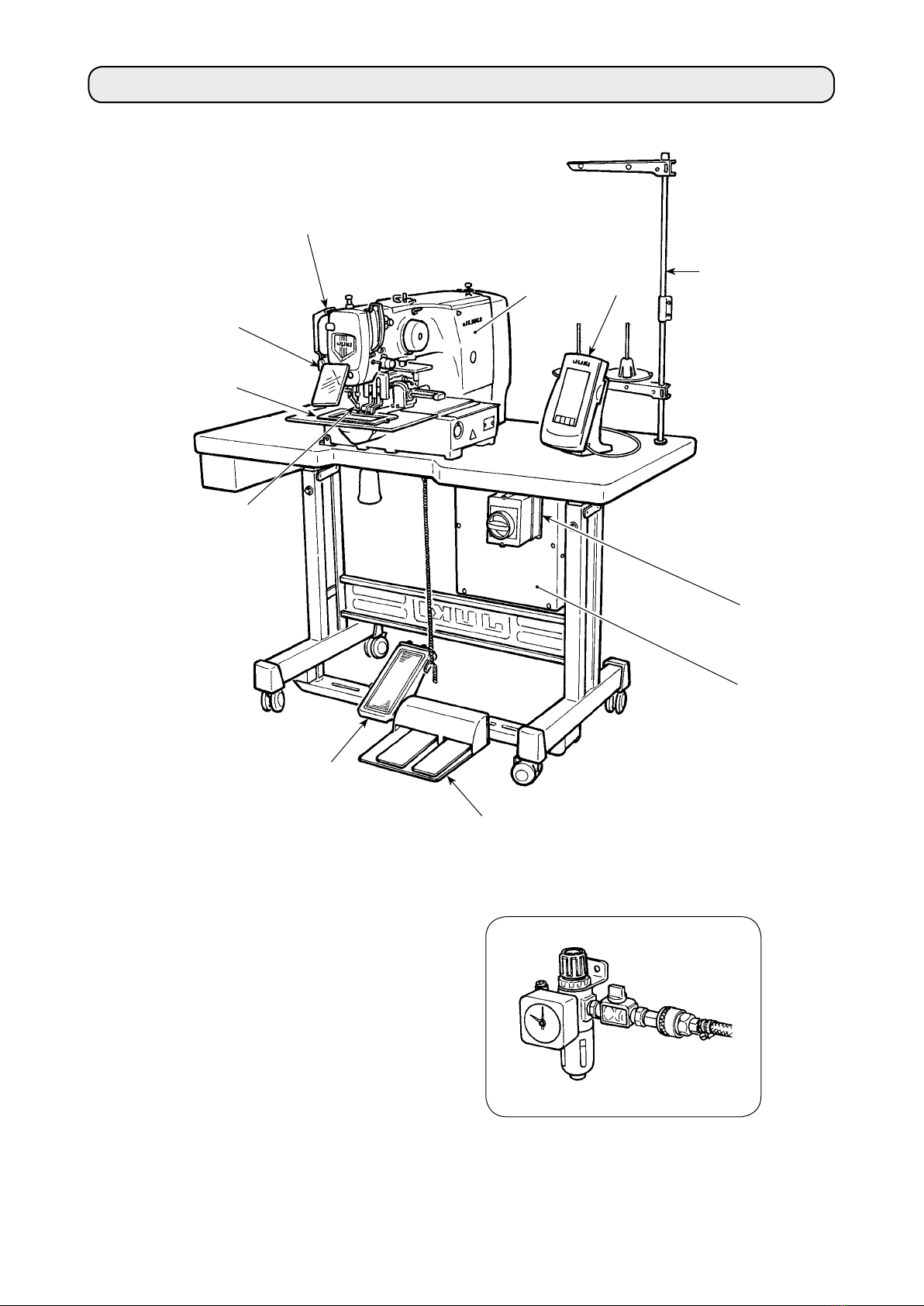
SanDisk AMS-210EN/IP-420 User manual

1
* "CompactFlash(TM)" is the registered trademark of SanDisk Corporation, U.S.A.
AMS-210EN / IP-420
INSTRUCTION MANUAL

i
CONTENTS
I. MECHANICAL SECTION (WITH REGARD TO THE SEWING MACHINE) 1
1. SPECIFICATIONS ....................................................................................................... 1
2. CONFIGURATION ....................................................................................................... 2
3. INSTALLATION ........................................................................................................... 3
3-1. Installing the electrical box...........................................................................................................3
3-2. Installing and connecting the power switch................................................................................ 3
3-3. Installation of the sewing machine head ..................................................................................... 5
3-4. Installing the drain receiver and the head support rubber ........................................................ 5
3-5. Safety switch ..................................................................................................................................6
3-6. Installing the throat plate auxiliary cover ....................................................................................6
3-7. Installing the panel.........................................................................................................................8
3-8. Attaching the pedal chain (For S specication only) ................................................................. 8
3-9. Installing the thread stand ............................................................................................................8
3-10. Raising the machine head...........................................................................................................9
3-11. Connecting the cord ..................................................................................................................10
3-12. Installing the motor cover .........................................................................................................13
3-13. Managing the cord .....................................................................................................................13
3-14. Connecting the pneumatic components (Pneumatic type only) ........................................... 14
3-15. Installing the air hose (Pneumatic type only).......................................................................... 17
3-16. Cautions for the compressed air supply (source of supply air) facility ............................... 18
3-17. Installing the eye protection cover...........................................................................................19
4. PREPARATION OF THE SEWING MACHINE .......................................................... 19
4-1. Lubrication....................................................................................................................................19
4-2. Attaching the needle....................................................................................................................19
4-3. Needle size and gauge.................................................................................................................20
(1) Adjustment ................................................................................................................................ 20
(2) Gauge.........................................................................................................................................20
4-4. Threading the machine head ......................................................................................................21
4-5. Installing and removing the bobbin case ..................................................................................21
4-6. Installing the bobbin....................................................................................................................22
4-7. Adjusting the thread tension ......................................................................................................22
4-8. Intermediate presser height........................................................................................................23
4-9. Adjusting the thread take-up spring ..........................................................................................23
5. OPERATION OF THE SEWING MACHINE............................................................... 24
5-1. Sewing...........................................................................................................................................24
5-2. Needle thread clamp device........................................................................................................25
II.
OPERATION SECTION (WITH REGARD TO THE PANEL)...............................................27
1. PREFACE .................................................................................................................. 27
2. WHEN USING IP-420 ................................................................................................ 31
2-1. Name of each section of IP-420 ..................................................................................................31
2-2. Buttons to be used in common ..................................................................................................32
2-3. Basic operation of IP-420 ............................................................................................................33
2-4. LCD display section at the time of sewing shape selection .................................................... 35
(1) Sewing shape data input screen .............................................................................................35
(2) Sewing screen...........................................................................................................................37

ii
2-5. Performing sewing shape selection...........................................................................................39
2-6. Changing item data......................................................................................................................41
2-7. Checking pattern shape ..............................................................................................................43
2-8. Performing modication of needle entry point ......................................................................... 44
(1) Editing the thread tension .......................................................................................................44
(2) Editing the intermediate presser height .................................................................................45
2-9. How to use temporary stop.........................................................................................................46
(1) To continue performing sewing from some point in sewing ................................................ 46
(2) To perform re-sewing from the start ....................................................................................... 47
2-10. When setting of sewing product is difcult because of interruption of needle tip ................... 48
2-11. Winding bobbin thread ..............................................................................................................49
(1) When performing winding bobbin thread while performing sewing ................................... 49
(2) When performing winding bobbin thread only ......................................................................49
2-12. Using counter.............................................................................................................................50
(1) Setting procedure of the counter ............................................................................................50
(2) Count-up releasing procedure ................................................................................................52
(3) How to change the counter value during sewing ..................................................................52
2-13. Performing new register of users’ pattern............................................................................... 53
2-14. Naming users’ pattern ...............................................................................................................54
2-15. Performing new register of pattern button.............................................................................. 55
2-16. LCD display section at the time of pattern button selection ................................................. 56
(1) Pattern button data input screen ............................................................................................56
(2) Sewing screen...........................................................................................................................58
2-17. Performing pattern button No. selection ................................................................................. 60
(1) Selection from the data input screen......................................................................................60
(2) Selection by means of the shortcut button............................................................................61
2-18. Changing contents of pattern button.......................................................................................62
2-19. Copying pattern button .............................................................................................................63
2-20. Changing sewing mode.............................................................................................................64
2-21. LCD display section at the time of combination sewing........................................................ 65
(1) Pattern input screen .................................................................................................................65
(2) Sewing screen...........................................................................................................................67
2-22. Performing combination sewing ..............................................................................................69
(1) Selection of combination data.................................................................................................69
(2) Creating procedure of the combination data .........................................................................70
(3) Deleting procedure of the combination data .........................................................................71
(4) Deleting procedure of the step of the combination data ......................................................71
(5) Setting of the skip of steps......................................................................................................72
2-23. Using the simple operation mode ............................................................................................72
2-24. LCD display when the simple operation is selected...............................................................73
(1) Data input screen (individual sewing) ....................................................................................73
(2) Sewing screen (individual sewing) .........................................................................................76
(3) Data input screen (combination sewing)................................................................................79
(4) Sewing screen (combination sewing).....................................................................................81
2-25. Changing memory switch data.................................................................................................83
2-26. Using information ......................................................................................................................84
(1) Observing the maintenance and inspection information ..................................................... 84
(2) Releasing procedure of the warning.......................................................................................85
2-27. Using communication function ................................................................................................86
(1) Handling possible data ............................................................................................................86

iii
(2) Performing communication by using the media ...................................................................86
(3) Performing communication by using USB.............................................................................86
(4) Take-in of the data ....................................................................................................................87
(5) Taking in plural data together..................................................................................................88
2-28. Performing formatting of the media.........................................................................................90
2-29. USING 2-STEP STROKE FUNCTION.........................................................................................91
(1) Setting of 2-step stroke function.............................................................................................91
(2) Setting of 2-step stroke position.............................................................................................91
(3) Motion of 2-step stroke function .............................................................................................93
2-30. Operation at the time of X/Y motor position slip..................................................................... 95
(1) When the error is displayed during sewing ...........................................................................95
(2) When the error is displayed after end of sewing...................................................................96
(3) When the rest switch is not displayed....................................................................................96
3. MEMORY SWITCH DATA LIST ................................................................................. 97
3-1. Data list .........................................................................................................................................97
3-2. Initial value list ...........................................................................................................................103
4. ERROR CODE LIST ................................................................................................ 105
5. MESSAGE LIST ...................................................................................................... 112
III. MAINTENANCE OF SAWING MACHINE...............................................115
1. MAINTENANCE....................................................................................................... 115
1-1. Adjusting the height of the needle bar (Changing the length of the needle) ....................... 115
1-2. Adjusting the needle-to-shuttle relation .................................................................................. 115
1-3. Height and angle of the work clamp......................................................................................... 117
(1) Height of the work clamp (S type)......................................................................................... 117
(2) Height of the work clamp (L type) ......................................................................................... 118
(3) Angle of the work clamp (all models excluding 1306L type) .............................................. 118
1-4. Adjusting the vertical stroke of the intermediate presser...................................................... 119
1-5. The moving knife and counter knife......................................................................................... 119
1-6. Needle thread clamp device...................................................................................................... 120
1-7. Thread breakage detector plate ...............................................................................................120
1-8. Draining waste oil ......................................................................................................................120
1-9. Amount of oil supplied to the hook..........................................................................................121
1-10. Replacing the fuse ...................................................................................................................121
1-11. Changing the voltage of 100 200V......................................................................................122
1-12. Replenishing the designated places with grease ................................................................. 123
(1) Location where exclusive grease is provided .....................................................................124
(2) Points to be applied with JUKI Grease A..............................................................................124
(3) Points to be applied with JUKI Grease B .............................................................................126
(4) Applying grease to other sections ........................................................................................127
1-13. Troubles and corrective measures (Sewing conditions)......................................................128
2. OPTIONAL............................................................................................................... 130
2-1. Table of Needle hole guide........................................................................................................130
2-2. Silicon oil tank ...........................................................................................................................130
2-3. Bar code reader..........................................................................................................................131

– 1 –
1. SPECIFICATIONS
I. MECHANICAL SECTION (WITH REGARD TO THE SEWING MACHINE)
1 Sewing area X (lateral) direction Y (longitudinal) direction
AMS-210EN-1306 : 130 mm × 60 mm
AMS-210EN-1510 : 150 mm × 100 mm
AMS-210EN-2210 : 220 mm × 100 mm
2 Max. sewing speed 2,800 sti/min (When sewing pitch is 4 mm or less)
3 Stitch length 0.1 to 12.7 mm (Min. resolution : 0.05 mm)
4Feed motion of feeding
frame
Intermittent feed (2-shaft drive by stepping motor)
5 Needle bar stroke 41.2 mm
6 Needle GROZ-BECKERT 134, 135 × 17, ORGAN needle DP × 5, DP × 17
7 Lift of feeding frame Max. 25mm (Pneumatic type only Max.30mm)
8
Intermediate presser stroke
4 mm (Standard) (0 to 10 mm)
9
Lift of intermediate presser
20 mm
10 Intermediate presser
DOWN position variable
Standard 0 to 3.5 mm (Max. 0 to 7.0 mm)
11 Shuttle Double-capacity semi-rotary hook
12 Lubricating oil New Defrix Oil No. 2 (Supplied by oiler)
13 Memory of pattern data Main body, Media
• Main body : Max. 999 patterns (Max. 50,000 stitches/pattern)
• Media : Max. 999 patterns (Max. 50,000 stitches/pattern)
14 Temporary stop facility Used to stop machine operation during a stitching cycle.
15 Enlarging / Reducing
facility
Allows a pattern to be enlarged or reduced on the X axis and Y axis independently
when sewing a pattern. Scale : 1% to 400% times (0.1% steps)
16 Enlarging / Reducing
method
Pattern enlargement / reduction can be done by increasing / decreasing either stitch
length or the number of stitches. (Increasing/decreasing stitch length only can be
performed when pattern button is selected.)
17 Max. sewing speed lim-
itation
200 to 2,800 sti/min (Scale : 100 sti/min steps)
18 Pattern selection facility Pattern No. selection method
(Main body : 1 to 999, Media : 1 to 999)
19 Bobbin thread counter UP/DOWN method (0 to 9,999)
20 Sewing counter UP/DOWN method (0 to 9,999)
21 Memory back-up In case of a power interruption, the pattern being used will automatically be stored in
memory.
22 2nd origin setting facility Using jog keys, a 2nd origin (needle position after a sewing cycle) can be set in the
desired position within the sewing area. The set 2nd origin is also stored in memory.
23 Sewing machine motor Servo-motor
24
Dimensions
1,200mm (W)
×
710mm (L)
×
1,200mm (H)
(Excluding thread stand)
25 Mass (gross mass) Machine head 69kg, control box 16.5kg
26 Power consumption 450 VA
27 Operating temperature
range
5˚C to 35˚C
28
Operating humidity range
35 % to 85 % (No dew condensation)
29 Line voltage Rated voltage ±10% 50 / 60 Hz
30 Air pressure used Standard 0.35 to 0.4 MPa (Max. 0.55 MPa)(Pneumatic type only)
31 Air consumption 1.8 dm3 / min (ANR) (Pneumatic type only)
32 Needle highest position
stop facility
After the completion of sewing, the needle can be brought up to its highest position.
33 Noise - Equivalent continuous emission sound pressure level (LpA) at the workstation :
A-weighted value of 82 dB; (Includes KpA = 2.5 dB); according to ISO 10821- C.6.2
-ISO 11204 GR2 at 2,800 sti/min *1.
- Sound power level (LWA) ;
A-weighted value of 91 dB; (Includes KWA = 2.5 dB); according to ISO 10821- C.6.2
-ISO 3744 GR2 at 2,800 sti/min *1.
Time required for sewing: 2.2 sec, using Pattern No. 102
*1"sti/min" is an abbreviation for "stitches per minute."

– 2 –
Air regulator
(for pneumatic type only)
2. CONFIGURATION
Machine head
Wiper switch
Temporary stop switch
Feeding frame
Intermediate presser
Thread stand
Operation panel (IP-420)
Power switch
(also used as the emergency stop switch)
Control box
Foot pedal
Manual pedal (Excluding pneumatic type)

– 3 –
3. INSTALLATION
3-1. Installing the electrical box
Install the electrical box on the underside of the
table at the location illustrated using round-head
bolt , plain washer , spring washer and nut
supplied with the machine, and using bolt hav-
ing hexagonal indentation on the head spring
washer and plain washer supplied with the
machine.
1) Installing the power switch
Fix power switch under the machine table
with wood screws .
Fix the cable with staples supplied with the
machine as accessories in accordance with the
forms of use.
Five staples including the staple for
xing the operation panel cable are
supplied as accessories.
3-2. Installing and connecting the power switch

– 4 –
(2) Connecting the power source cord
The factory default voltage type is indicated on the voltage indication plate. Connect the cord in ac-
cordance with the specications.
Voltage indication seal (3-phase type only)
Voltage caution seal
Rating label
Brown
Brown
Light blue
Light blue
Light blue
Green/Yellow
– GND
Green/
Yellow
Plug
Power source cord
Power switch
AC200 V, AC220 V
AC230 V, AC240 V
• Connecting single phase
200V, 220V, 230V and 240V
White
AC200 V, AC220 V, AC240 V
• Connecting three phase
200V, 220V and 240V
Red White
Black
1. Never use under the wrong volt-
age and phase.
2. When changing the voltage, refer
to the item of
"III-1-11. Changing the voltage of
100 200V" p.122
Table
Control box
Black
Red
Green/
Yellow
Brown
Green/Yellow
– GND
Red
Green
PlugControl box
Green/
Yellow
Black
White
Power switch
Table
Electric shock
warning label

– 5 –
1) Fit the holes of hinges to the holes of table
and x as shown in the gure.
3-3. Installation of the sewing machine head
In case of the pneumatic type, x sole-
noid valve installing plate as well.
WARNING :
To prevent possible accidents caused by the full of the sewing machine, perform the work by two
persons or more when the machine is moved.
3-4. Installing the drain receiver and the head support rubber
1) Fix drain receiver in the installing hole of
table with two setscrews .
2) Screw in drain bin to drain receiver .
3) Insert sewing machine drain pipe into drain
bin .
4) Insert head support rubbers to machine bed .
5) Bundle the cables with clip bands as shown
in the gure. (Excluding air tube)
1. Insert drain pipe until it will go
no further so that it does not come
off drain bin when tilting the ma-
chine head.
2. Remove the tape xing drain pipe
.

– 6 –
3-6. Installing the throat plate auxiliary cover
[When using area 1306]
1) Temporarily x throat plate auxiliary
cover supports A and B to the
machine bed with setscrews (M5) .
2) Move the cloth feed base to the rear,
and place throat plate auxiliary cover
from between lower plate and
throat plate . At this time, be careful
not to bend lower plate .
3) Fix throat plate auxiliary cover with
throat plate auxiliary cover setscrews
and washers .
[Area 1306]
3-5. Safety switch
Remove tape xing the lever section of safety
switch .
1. When using the safety switch
without removing tape , it is very
dangerous since the sewing ma-
chine works even in the state that it
is tilted.
2. In case error 302 occurs when the
sewing machine works after setup,
loosen the safety switch tting
screw with a screwdriver, and lower
the switch to the downside of the
sewing machine.
WARNING :
Be careful not to bump your head or any other parts of your body against the throat plate auxiliary
cover when you bend over your work.

– 7 –
Left-hand and right-hand shapes of throat plate auxiliary cover support are different. So,
be careful.
Within 0.3 mm
2
[Areas 1510 and 2210]
[When area 1510 or 2210 is used]
1) Temporarily x throat plate auxiliary
cover supports A and B to the
machine bed with setscrews (M5) .
For the screw which tightens
the throat plate auxiliary cover
support A , select the screw
which is easier to use between
the hexagon socket and the
screw with plus and minus
slots.
2) Move the cloth feed base to the rear,
and place throat plate auxiliary cover
from between lower plate and
throat plate . At this time, be careful
not to bend lower plate .
3) Fix throat plate auxiliary cover with
throat plate auxiliary cover setscrews
and nuts (small) .
4) Temporarily fix throat plate auxiliary
cover support to the machine bed
with setscrews (M6) .
5) Temporarily fix throat plate auxiliary
cover base to throat plate auxiliary
cover support with setscrews and
nuts (large) .
6) Fix throat plate auxiliary cover with
throat plate auxiliary cover setscrews
and nuts (large) .
1. Be careful so as not to mis-
take the direction of throat
plate auxiliary cover support.
2. Fix the throat plate auxiliary
cover so that is higher than
the throat plate (within 0.3
mm). When it is lower than
the throat plate , needle
breakage or the like due to the
defective feed will be caused.
3. Conrm by putting a ruler or
the like that the throat plate
auxiliary cover is horizon-
tally installed. If not, throat
plate auxiliary cover and
lower plate come in contact
partially with each other, and
abnormal worn-out will be
caused.
[Areas 1510 and 2210]

– 8 –
3-8. Attaching the pedal chain (For S specication only)
3-9. Installing the thread stand
1) Assemble the thread stand, and put
it in the hole in the top left corner of
the machine table.
2) Tighten locknut to x the thread
stand.
3) When ceiling wiring is possible, pass
the power cord through spool rest
rod .
Connect the machine and manual pedal with
chain .
When you tilt the sewing machine, be
sure to tilt it after removing chain
from manual pedal .
3-7. Installing the panel
1) Installing the IP-420
1) Open cover and remove cable once.
Then connect it again to the panel on the top
surface of the table after passing it through the
hole in the table.
2) Fix operation panel installing plate to an op-
tional place on the table with two wood screws
.
Install the panel at the position where
X-move cover or head grip does not
interfere with it since breakage of the
panel will be caused.

– 9 –
3-10. Raising the machine head
WARNING :
When tilting or raising the sewing machine, be careful not to get your ngers caught between the
sewing machine and table. In addition, be sure to turn the power off before titling/raising the sew-
ing machine so as to protect against accidents resulting from unintentional starting.
[When area 1306 or 1510 is used]
To raise the sewing machine, carefully raise it until
bed support rubber comes in contact with the
table while holding section into which the sewing
machine bed is to be inserted by hand. For the S
type, remove chain from manual pedal rst,
and perform the work.
1. Be sure to raise the machine head at
the leveled place so as to prevent the
sewing machine from falling.
2. When raising the machine head,
move feeding frame beforehand
to the right-hand side until it goes
no further, and x it with tape or
the like. When the machine head is
raised in the state that moving or
xing is insufcient, breakage of
X-move cover or X-move rail will be
caused. Besides, feeding frame
which is tilted to the left-hand side
by the self-weight interferes with the
intermediate presser or the like and
breakage of the components will be
caused.
[When using area 2210]
1) Remove throat plate auxiliary cover
from the sewing machine.
2) Hold inserting section of the ma-
chine bed by hand, and quietly raise
it until bed support rubber comes
in contact with the table.
3) After returning the sewing machine
to its home position, refer to "I-3-6.
Installing the throat plate auxil-
iary cover" p.6 , and install the
throat plate auxiliary cover.
1. Be sure to raise the machine head at the leveled place so as to prevent the sewing ma-
chine from falling.
2. When raising the sewing machine without removing throat plate auxiliary cover , the
throat plate auxiliary cover interferes with the table, bend or breakage of the throat plate
auxiliary cover, tilt of the sewing machine, etc. will result.
3. When raising the machine head, move feeding frame beforehand to the right-hand
side until it goes no further, and x it with tape or the like. When the machine head is
raised in the state that moving or xing is insufcient, breakage of X-move cover or
X-move rail will be caused. Besides, feeding frame which is tilted to the left-hand side
by the self-weight interferes with the intermediate presser or the like and breakage of
the components will be caused.
[Area 2210]

– 10 –
3-11. Connecting the cord
Slowly
❶
[How to open the control box]
Remove four screws ❶ xing the rear cover of
the electrical box. When opening the rear cover,
pressing it with your hands, slowly open it by ap-
proximately 90˚ until it stops as illustrated.
Be sure to lend your hand to the rear
cover in order not to let the rear cover
fall. In addition, do not apply force to
the rear cover opened.
[How to close the control box]
1) Take care so that the cord is not
caught between the rear cover and
the electrical box main body, close the
rear cover while pressing section Aon
the lower side of the rear cover, and
tighten four screws ❶.
2) Lower downward the cord located on
the side of the control box and cord
presser plate Cin the though hole B,
press the cord and tighten screws ❷.
❸
❶
❷
❶❶
❷
How to remove the cord clamp
❷
A
B
❶
When xing the cord with the cord clamp, be careful of the route or the like so that the
stress is not applied to the cord.
C
How to lock the cord clamp
①Lightly press
the corner
of clamp.
(Cord clamp is
locked with a
click.)
①Lightly pressing
②Pull down the clamp.
③The clamp goes up.
Clamp
❶

– 11 –
[Wiring diagram of circuit board]
CN16
CN14
CN38
CN40
CN39
CN53
CN47
9P
IP-420F
4P
20P
10P
CN88
26P
12P 12P
CN98
CN78
4P
2P
CN1
2P
CN100
2P
CN51
10P
Air-driven type
CN34 26P
12P
2P
2P
7P
CN56
CN43
CN55
CN41
CN54
CN42
5P
4P
7P
4P
7P
4P
7P
4P
10P
CN22
FG
FG
2P
2P
2P
2P
CN1
CN2
CN3
CN4
CN5
FG
P1
P2
P3
P4
2P
12P
2P
CN85
CN52 CN52
CN85 2P
2P
2P
CN2
CN3
CNS
3P
Air-driven type
FG
Sewing machine head
SDC p.c.b.
MAIN p.c.b.
MAIN p.c.b.

– 12 –
CN16 4P CN14 9P
SDC p.c.b.
MAIN p.c.b.
FLT p.c.b.
FLT-T p.c.b (single phase 100 to 200V、
three phase 200 to 240V)
FLT-S p.c.b (single phase 200 to 240V)
CN40 4P Red
CN88 10P
CN34 26P
CN38 20P
CN47 2P
CN39 2P
Yellow
CN52 2P White
(Air-driven type)
CN22 5P White
CN85 12P Black (Air-driven type)
CN54 7P White
CN43 4P Blue
CN42 4P Black
CN55 7P Black
CN56 7P Yellow
CN41 4P White
CN53 7P Red

– 13 –
3-12. Installing the motor cover
Install motor cover on the machine main unit
with screws supplied with the machine as acces-
sories.
3-13. Managing the cord
1) Fix the cords with cords setting plate in the state that the cords are slack to such an extent that
stress is not applied to the cords even when the machine head is tilted as shown in the gure.
Slack
2) Secure the cable to be put into the POWER
BOX with an internal cable clip .

– 14 –
4) Fix the air tube using cable clip supplied with
the machine as accessories. (For the setscrew,
use setscrew xing the motor cover.)
3) Install solenoid valve asm. on solenoid
valve installing plate in the direction as
shown in the gure, using screw supplied as
accessories.
In addition, x one side of accessory ground
code (length: 20 cm) with setscrew
together with solenoid valve mounting plate .
3-14. Connecting the pneumatic components (Pneumatic type only)
1) Install regulator to installing plate , and
install it to the stand with screw , washer
and nut .
2) Connect the cord coming from the regulator
with CN78 (air relay cable).
(Refer to"I-3-11. Connecting the cord [Wiring
diagram of circuit board]" p.11.)
[Connection common to all areas]
When using the air-driven type model, connect the pneumatic components as described below.

– 15 –
5) Install solenoid valve installing plate A asm.
on the table with two setscrews .
Connect solenoid valve installing plate A
asm and regulator ❶with long air tube
supplied as accessories with the machine.
In addition, x the other side of ground cord ❾
(length: 20 cm) which has been attached in the
aforementioned Step 3), with screw Awhich is
secured with joint, together with the joint. Then,
x one side of accessory ground cord (length:
80 cm) with screw B which xes the joint,
together with the joint.
Attach the relevant components referring to the
illustrations.
Table
6) Fix the other side of ground cord (length: 80
cm) on the bottom section inside the control
box, using accessory M4 screw .
❻
❾
B
A

– 16 –
Connector
CN1
Air tube
1A
Air tube
1B
6) Install air tubes coming from the machine head
and the cords coming from the control box to
the position as shown in the gure. At this time,
be careful of the number and alphabet of the
air tubes and the cords. (Adjust the alphabet
of the air tubes to the alphabet of the solenoid
valve. Also, adjust the gures to the gures of
the connector label.)
7) Connect air tube of solenoid valve installing
plate A asm. to solenoid valve asm. .
[When using area 1306]
When area 1306 is used, connect the pneumatic components after having carried out [Connection
common to all areas].
Air tube 2B
8) Install the air tubes coming from the machine
head to the joint of solenoid valve installing
plate A asm. as shown in the gure.
Install two stop plugs supplied as accesso-
ries to and .
Install cords (CN2, CN3, CNS) coming from the
control box to the solenoid valve.
If a cable has a slack, x the cable on
the table by means of a stapler sup-
plied with the unit.
At this time, provide the cable with an
adequate play (allowance) to prevent
the related connector from being ap-
plied with an excessive load.
CN3
Air tube 2A
CN2
CNS
Table of contents
Other SanDisk Sewing Machine manuals