6
COLUMBIA SPECIFICATIONS
800.626.2117 columbiasinks.com info@columbiasinks.com
©2021 Columbia Products
SENSOR FAUCETS
SANI-LAV Sensor Faucets
Wall Mounted AC and Battery Powered
Meets ANSI/ASME A112.18.1 M-1989
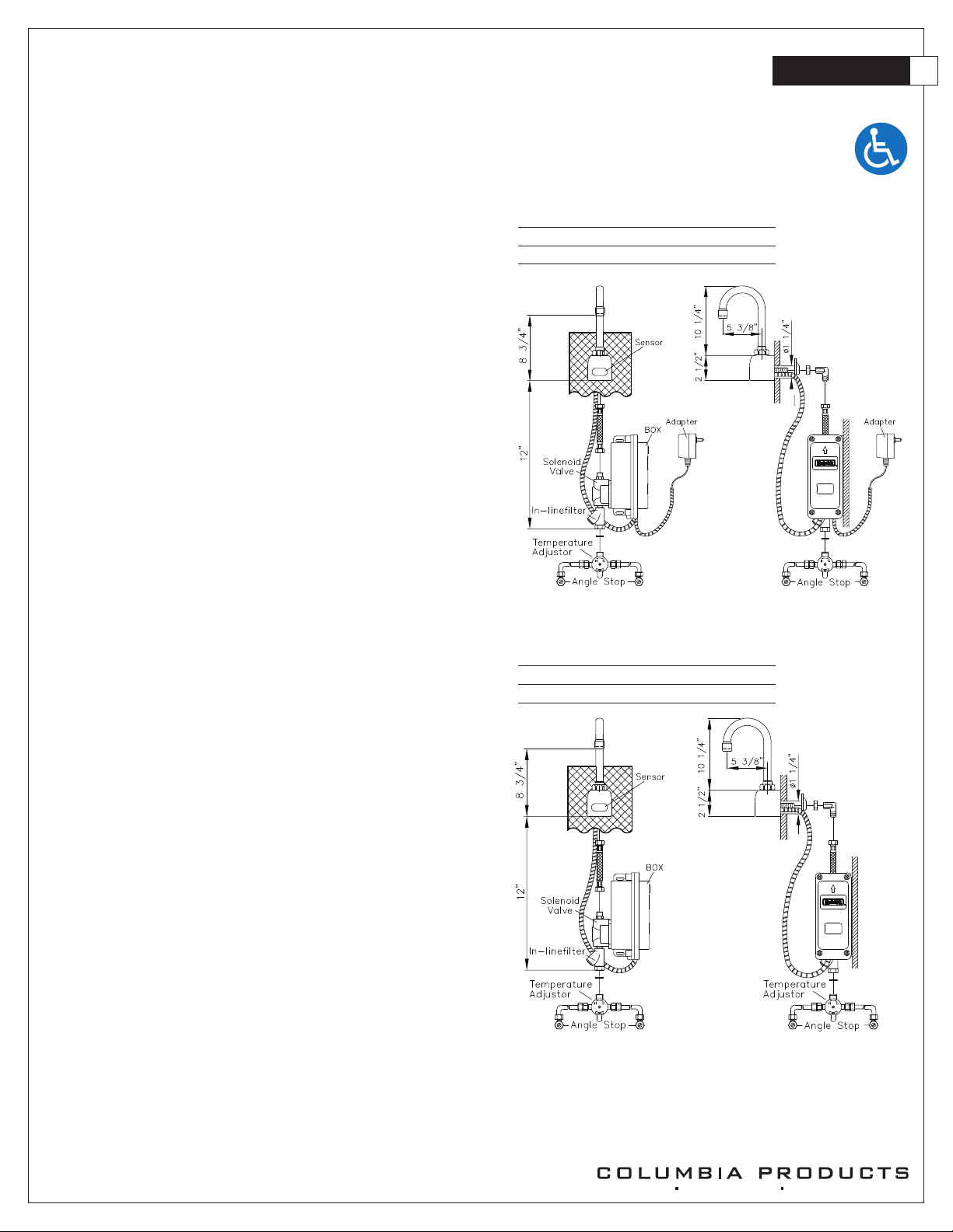
Operation
1. A continuous, invisible beam is emitted from the sensor.
2. The faucet is activated by placing hands under the spout within the effective
range of the beam. Water starts to flow immediately for as long as the user’s
hands remain in the sensor range.
3. When hands are removed, the water flow stops. The sensor will automatically
reset and be ready for the next user.
4. In the battery powered version, a flashing red light will indicate a low battery
condition.
Specifications
Faucet Construction Solid brass, chrome plated
Control Circuit Solid state, AC or battery, switchable
– Auto. Time-out Preset at 20 seconds and adjustable to 10,
30, or 60 seconds
– Line Purge (request only) 2 minute run every 12 hours
or 24 hours
– Scrub Mode Delay (request only) 60, 120, 180 seconds
– Sensor Range Preset and adjustable
– Shut-off Delay Presets and adjustable from 1-8 seconds
Control Cable Armored, vandal resistant
Solenoid Valve 6V DC, normally closed
– Wattage: 0.4W (idle), 5W (in use)
– Operating Pressure: 5 psi to 125 psi
Flow Control 2.0 or 0.5 GPM, Laminar Flow Control
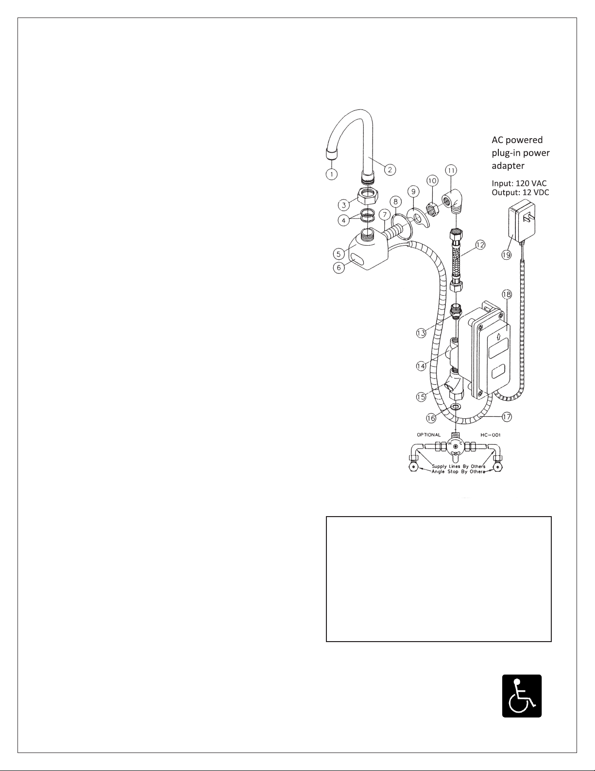
AC Mode
Power Adapter
– Standard Plug-in Input AC 120V 60 Hz or 220V
– (UL/CSA) Output DC 12V, 0.8A/Class 2
Power Cable Armored, vandal resistant
– Optional Multi-Unit Adapter Serves up to 8 faucets
– (UL/CSA) Input AC 120V, Output DC 12V, 3A
Battery Mode
Battery Powered Models (4) AA Alkaline Batteries
Battery Service Life 400,000 on/off cycles, up to 4 years
Package Includes
(1) Faucet with electronic sensor
(1) Control box w/6V DC solenoid
(1) 12V DC plug-in power adaptor (H-6700C, -DC, -LR and -LRDC only)
(1) In-line filter with clean-out trap
(1) 18” Flex, S.S. supply tube, 3/8”(1) 6” Gooseneck Spout
(1) Mounting hardware
(1) 2.0 GPM Flow Control(4) AA Alkaline batteries (HB-6700C, -DC, -LR, -LRDC only)
(1) Battery holder (HB-6700C, -DC, -LR, -LRDC only)
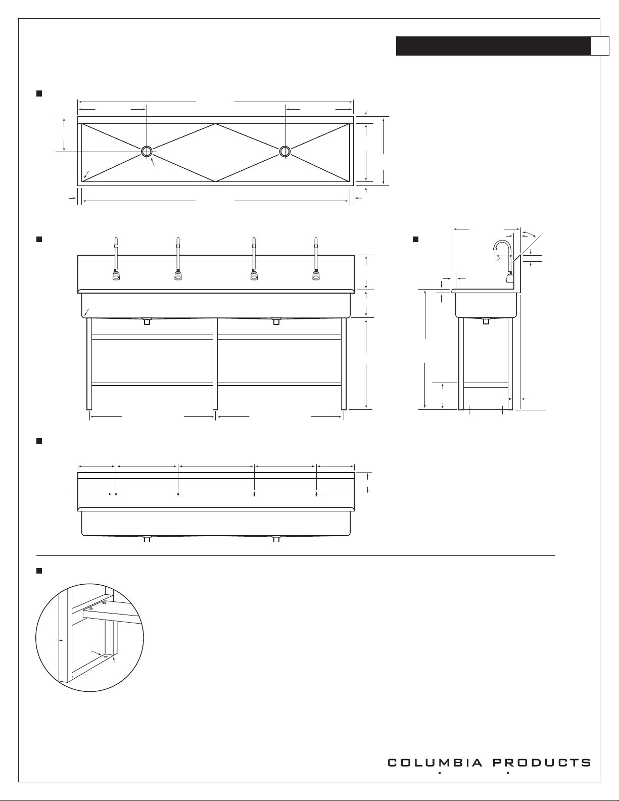
Dimensions
– Base Width (Outside Measurement) 2-1/4”
– Base Depth 2-1/2”
– Faucet Height (Aerator to Base) 8-3/4”
– Faucet Height Overall 12-3/4”
– Depth (Center of Aerator to Center of Faucet Base) 5-3/8”
– Mounting Bolt Length 1-7/16”
– Mounting Bolt Pattern Single-hole mount
Optional Variations and Accessories
– 0.35, 0.5, 1.5, 2.2 GPM Laminar Flow
– HC-010 Multi-Unit Voltage Adapter (AC Powered Only) - 8 units
– HC-0104 Multi-Unit Voltage Adapter (AC Powered Only) - 4 units
– HC-001 Mixing/Check Valve (Mechanical)
– HBL-04-LR Thermostatic Mixing Valve with Checks (Low Lead)
– 8” deep Gooseneck and 6” or 8” Swing Swing SpoutModel
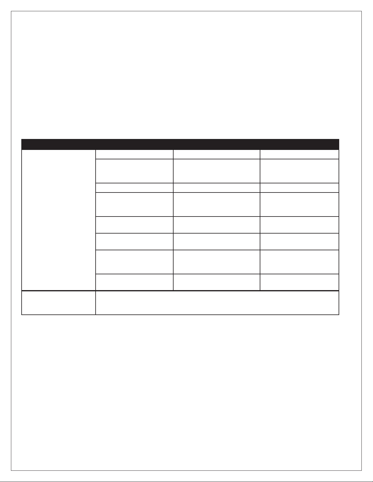
Model Sensor Type Flow-Rate
ES2RL AC Powered Standard 2.0 GPM
ES2RL-0.5 AC Powered Low-Flow 0.5 GPM
Model Sensor Type Flow-Rate
ESB2RL Battery Powered Standard 2.0 GPM
ESB2RL-0.5 Battery Powered Low-Flow 0.5 GPM
ADA Compliant