manuals.online logo
Brands
  1. Home
  2. •
  3. Brands
  4. •
  5. Sanyo
  6. •
  7. Microwave Oven
  8. •
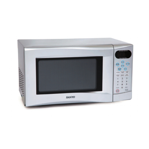
  9. Sanyo EM-V758 User manual

Sanyo EM-V758 User manual

. .. . . ... ..
.. .... ..’.
?
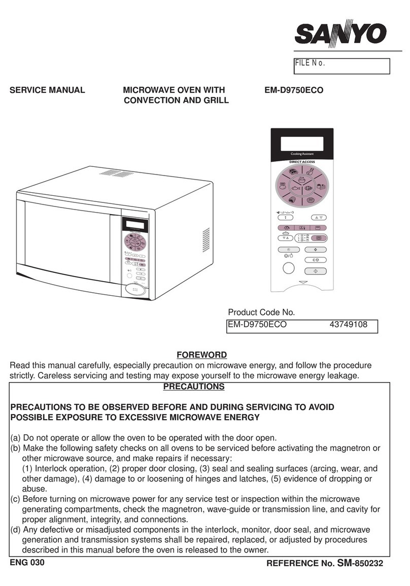
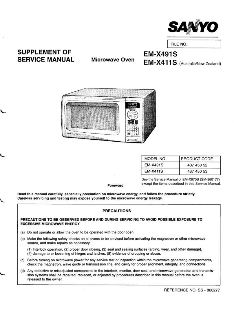
SUPPLEMENT OF
SERVICE MANUAL
.“--.
..
. .
Microwave Oven
*O
FILE NO. I
EM-V’758 (Newzealand)
\
-...
...
..-’
Product Code No. 437-293-51 1
See the service manual of EM-V860 (SM-640126)
except the items described in this service manual.
Foreword
,:.. ...
Read this manual carefully, especially precaution on microwave energy, and follow the procedure strictly. Careless ser- -
vicing and testing may expose yourself to the microwave energy leakage.
PRECAUTIONS
PRECAUTIONS TO BE OBSERVED BEFORE AND DURING SERVICING TO AVOID POSSIBLE EXPOSURE TO EXCES-
SIVE MICROWAVE ENERGY
(a)
(b)
(c)
(d)
Do not operate or allow the oven to be operated with the door open.
Make the following safety checks on all ovens to be serviced before activating the magnetron or other micro-
wave source, and make repairs as necessary:
(1) Interlock operation, (2) proper door closing, (3) seal and sealing surfaces (arcing, wear, and other dam-
age), (4) damage to or loosening of hinges and latches, (5) evidence of dropping or abuse.
Before turning on microwave power for any service test or inspection within the microwave generating com-
partments, check the magnetron, wave guide or transmission line, and cavity for proper alignment, integrity,
and connections.
Any defective or misadjusted components in the interlock, monitor, door seal, and microwave generation and
transmission systems shall be repaired, replaced, or adjusted by procedures described in this manual before
the oven is released to the owner.
REFERENCE NO. SS-640127
ii
–TABLE OF CONTENTS–
Specifications ........................................................................ 1Test Procedures ..................................................................... 3
Power Output Measurement ...............................................1 Exploded View and Pans List ........................................4-8
Circuit Diagram ..................................................................... 2Overall Circuit Diagram ........................................................ 9
I. SPECIFICATIONS
Rated Power Consumption .......
Microwave Output .....................
Frequency ...................................
Power Supply .............................
Rated Current .............................
Safety Devices ...........................
Timer ...........................................
Overall Dimensions ...................
Oven Cavity Size ........................
Turn Table Diameter .................
Effective Capacity of
Oven Cavity .........................
Net Weight .................................
1400W
900W
(Adjustable 130W through
900W)
2,450 MHz?50MHz
240V, 50 HZ
6.0 Amp.
Thermal Protector, Open
at 122° Cfor Cavity
Thermal Protector: Open
at 1350 Cfor Magnetron
Fuse (Cartridge Type 8A)
Primary Interlock Switch
Door Sensing Switch and
Relay 2
interlock Monitor Switch
Electronic Digital, up to
99 min. 99 sec.
525( W) X420( D) X281(H)
mm
350( W) X370( D) X208(H)
mm
340mm
26 liters
Approx. 16 Kg
2. POWER OUTPUT MEASUREMENT
NOTE
The power output specification 900W on this model is
“rfmeasured with IEC measurement. The power output I
measured with two (2) liters water is equivalent to 900W
in measurement with IEC, when measured with the
following power outwt.
(A) 1. Fill two test bowls with each 1liter water
respectively.
2. Use accurate temperature 0Cand measure each
water temperature respectively.
(B) Place the two bowls on glass turntable.
(C) 1. Set cooking time to two (2) minutes. (“2 00”
appears in display)
2. Touch START key and o~erate oven for exactlv two
(2) minutes.
(D) 1. Take out the two bowls at once.
2. Stir both water with thermometer ana measure the
water temperature rise respectively.
(E) :. Get temperature rise by calculation the difference
(water temperature after cooking minus initial
temperature) in each bowl.
2. Then calculate average value(t) of both temperature .~~’.
. . . ..
rises in degrees centigrade. .. .
3. Then work out;
Power Output (watt) =70 x t
(F) Power output shall be in the following range
Average Microwave
temperature rise Power Output
(G) Power Output will be influenced by line voltage of
power supply. Consequently, correct power output
must be measured within 240V AC* 2volt while unit is
operating.
: ..
–l–
ii
. .”...”...”. .“
3. CIRCUIT DIAGRAM
.,.
.
.. .
THERMAL PROTECTOR
FOR CAVITY OPEN 122t5°C
r“i
‘z’ dCAVITYLAMP
L.— __J 2200PF
=
wBK (
THERMAL PROTECTOR L
FOR MAGNETRON OPEN
135!5°C
wf
IS1
+
11
I
‘-k
13
I
15
I
I
I
I
1
I
I
I
I
I
I
1–.
i2!3
i
II650JIH “2 BR n
II
0.068PF II
~I
!CONNECTOR \
rGEAR MOTOR
)BK
“
INTERLOCK i\
PRIMARY
INTERLOCI
SWITCH
NC
--(Y
IBLOWER MOTOR HIGH VOLTAGE TRANSFORMER
~_–——–_—–.––—– —..
IK
cCONTROL
CIRCUIT
BOARD
K
CONNECTOR
JSlol
l———_--l
——— ——— — —— — ——— —
TOUCH
KEY
BOARD
:OM
o
~
\
NO
.—-— ———— ——— 1wI●m
)
———— —.
Io
I~
I10MEG.OHM
1BK
WIRING COLOR
BK :BLACK BR :BROWN
W:WHITE BL :BLUE
O:ORANGE
R:RED Figure 1
Parts marked with this sign are supplied with
high voltage exceeding 250V.
Parts marked with this sign have special
characteristics important for microwave leakage.
When replacing any of these parts use only
manufacturers specified parts.
El
●NOTE:
CAPACITYI
WORKING VOLT
I1.03MFD2.1KVAC EM-V758 I
II
/1. IMFD2KVAC ]EM-v860 I
1II
–2–
4. TEST PROCEDURES
cOMPONENT
ONTROL
IRCUIT BOARD
rOUCH KEY
30ARD
CHECKOUT PROCEDURE
Measure the voltage: Between test points
TP-1, TP-2 or TP-3 and ground between
TP-4, and TP-5. (See control circuit board
on page 9)NOTE
–Proceed with the check of the step-down
transformer, to see if any one of the
measured values is different from the
specified values.
Measure the resistance between terminals,
of FPC connector after removing it from
SIO1. (Figure 2). NOTE -
—When reconnecting the FPC connector,
make sure the holes on the connector are
propedy inserted in hooks of the plastic
fastener in S101.
MATRIX CIRCUIT FOR
TOUCH KEY BOARD
FPC CONNECTOR
RESULT I
Test TP-2 TP-3 TP-41
TP-1
point TP-5
–5V –15V –25V 2.OV
Voltage DC Dc DC AC
1--1 II
I
When When not
Resistance touched touched
value Less than More then
lK Ohms 1MEG Ohm
When checking “START” key, connect ohm-
meter as illustration below
Q
Ohm-meter
1
Top
b;B
t
_-—
-
--
.-—
D
—- 1
--
-- I
I
—-- I
—-- 0’
-—- 11
-- —.Z
Al
A2
A3 )
A4
A5
c1
C2
C3 )
C4
C5
Figure 2
TERMINALS OF FPC CONNECTOR
..”
–3–
5. EXPLODED VIEW AND PARTS LIST
CAVITY PA
.-.
3
,- ”..
-.
.,
.-
’20
21 8
b“”Al_l_SERVICE ON MICROWAVE OVENS SHOULD BE PERFORMED BY AQUALIFIED TECHNICIAN
USING APPROVED TESTING EQUIPMENT. CUSTOMERS SHOULD NOT ATTEMPT TO REPLACE PARTS
ID ENTIFIED BY ATRIPLE ASTER ISK(***)
Key
No. Part No. Description Q’ty
16171240764 Cabinet 1
2 4110825201 Screw, Truss Hd. Tapping, 4x10mm 6
3 411 1606007 Screw, TPG TRS+SRT 4x10mm 4
46171451412 Oven Cavity ***(Nol service part) 1
5 617151 2458 Gear Motor 1
6411 0105808 Screw, Pan Hd. Machine, 4x10mm, 2
Brass, N1
76171385601 Bottom Plate*”* 1
8 6171445435 Plastic Foot with Canoe Clip 4
9411011 0802 Bolt, Hex. Hd. Machine with Spring
Washer &Bolt Washer, 5X 14mm, 2
Z,***
10 6171240795 Hinge, Lower*** 1
11 411 0892500 Washer, 5mm, U1
12 6170805315 Special Washer 1
–4–
Key
No. Part No. Description Q’ty
13 6171322095 Turn Table Shaft 1
14 6171242416 Roller 1
15 6171242393 Rotating Tray 1
16
17 411 0076900 Screw, Pan Hal., Tapping, 3x6mm. 1
C2-2
18 6171241235 Thermostat, Cavity 122°C 1
19 6171208481 Insulation Sheet 1
20 6171184679 Insulation Sheet 1
21 411 1606106 Screw, S-TPG TRS+SRT 4x10mm 1
22 6171246209 Stirrer Assembly 1
23 6171451429 Stirrer Cover 1
24 411 1606205 Screw, Tapping TRS +SRT 4x10mm 1
●6171385090 Circuit Diagram 1
●6171583939 Name Plate 1
‘Items not illustrated.
..
SWITCHES AND MICROWAVE PARTS
ii
2[T’
m
I
I
Q!L
/23
Parts msrked with this sign are supplied with
high voltage exceeding 250V.
u_
oPsrts marked with this sign have special
~characteristics important for micmwsve leakage.
When replacing any of these parts use only
manufacturers specified parts.
F
No.
1
2
3
4
5
6
7
8
9
10
11
12
13
14
15
16
17
●“* ALL SERVICE CIN MICROWAVE OVENS SHOU
USING APPROVED TESTING EQUIPMENT. CUS7
IDENTIFIED BY ATRIPLE ASTER ISK(***)
Part No.
4110825201
6171385113
6171451641
6171449808
6171385700
4110076900
6171241259
4150021502
4230227503
6171414042
6171451627
6171405354
6171378870
6171395228
6171241082
6171305685
4110772109
Description
Screw, Truss Hd. Tapping, 4x10mm
‘ower Supply Cord Complete
-ligh Voltage Transformer, H5T-
?04SAP
Duct, Msg. Inlet
Stay, Cavity &Magnetron
Screw, Pan Hd. Tapping, 3x6mm,
C2-2
Thermostat, Magnetron, 135’C
Magnetron, 2M219H(B)***
Fuse, 250V 8A
Printed Circuit Board Complete
Lead Wire Ass’y with Diode
Lead Wire Ass’Y (Transformer to
Capacitor)
Capacitor Band
High Voltage Capacitor including
Resistor, 1.03uf 2.1 KV
Space Partition (810wer)
Blower Motor
Screw, Truss Hd. Tapping, 4x20mm,
Z1-1
Qty
6
1
1
1
1
2
1
1
1
1
1
1
1
1
1
1
2
u“
13’
LD BE PERFORMED
.OMERS SHOULD NO
K
No.
18
19
20
21
22
23
24
25
26
27
28
29
30
31
32
33
34
—
–5–
. .
BY
TAT
lZ
AQUALIFIED TECHNICIAN
‘TEMPT TO REPLACE PARTS
Part No. ~
i17 075 1179
111011 5609
517 1405330
517 1103618
6171241280
6171241181
6171524741
6171525106
6171241174
411 1025808
4120182004
411 1606106
6171325713
4110541903
Description
310wer Fan
3olt HEX 4x20
>uct, Msg. Exhaust
Lamp, 240V 25W
Lamp Socket
Latch Lever”+”
Micro Switch, Primary Interlock and
Door Sensing V-5930D***
Micro Swtich, Interlock Monitor
V-5920D***
Lever Stopper***
Screw, E-Tapping TRS+TW,
4x12mm, 21
BOLT HEX C-SCT 5x16mm
Screw, Tapping TRS+SRT 4x1 Omm
Insulation Sheet
NUT HEX+FLG W/SRT 5
My
1
3
1
1
1
1
2
1
1
2
2
2
1
2
i
DOOR PARTS
..
G
No.
1
2
3
4
5
/
8***
&/7 *“* 4*** FI
1(J***
/
9***
“’* ALL SERVICE ON MICROWAVE OVENS SHOULD BE PERFORMED BY AQUALIFIED TECHNICIAN
USING APPROVED TESTING EQUIPMENT. CUSTOMERS SHOULD NOT ATTEMPT TO REPLACE PARTS
ID ENTIFIED BY ATRIPLE ASTER ISK(**’)
Part No.
6171514216
6171514223
6171385625
6171520804
6171240931
Description
Door Cover**”
Door Panel’”’
Door Main Frame*** (Also cwder
Door Shet when replacing Door
Main Frame)
Choke Dielectric***
Door Sheet***
C1’ty
1
1
1
1
1
Key
No. Part No. Description C1’ty
6411 0541903 Nut, Nex. Hd. with Washer, 5mm 2
76171240955 Hinge, Upper*** 1
8411 011 0802 Bolt, Hex. Hd. Machine with Spring
Washer and Bolt Washer, 5x14mm, 2
Z1***
9 617101 1494 Spring*”* 1
10 617101 1487 Door Latch’+” 1
–6–
CONTROL PANEL PARTS
6***
/
5***
\
b
\
2***
1
‘,.
g***
..
●☛☛ ALL SERVICE ON MICROWAVE OVENS SHOULD BE PERFORMED BY AQUALIFIED TECHNICIAN
USING APPROVED TESTING EQUIPMENT. CUSTOMERS SHOULD NOT ATTEMPT TO REPLACE PARTS
ID ENTIFIED BY ATRIPLE ASTER ISK(***)
Key
No.
1
PartNo, Description Q’ty Key
No. Part No. IDescription Ia’ty
Control Sheet (Also order Touch Key
Board when replacing Control Sheet)
Touch Key Board*** (Also order
Control Sheet when replacing Touch
Key Board)
Control Plate (Display)”’”
Control Frame*’*
1
1
5
6
7
8
931_E
6171566598 Control Circuit Board Complete
411 1295805 Screw TPG BIN 3x10mm
6170809559 Spring, Door Release Lever***
617 151 4339 Door Release Lever***
6171569339
61715143842
1
1
3
4
6171514346
6171514360
PRINTED MATTER
(Items Not Illustrated)
Key
No. Part No. Description Q’ty
I
II6171569353 10perating Instructions Ill
II6171546477 ICarton BOX Ill
–7-
ii
CONTROL CIRCUIT BOARD
(Part No. 617156 6598)
,.,
.-
r
TP-4
CT’-’
TP-3
—TP-1
TP-2
Ground
–8–
. .. .,. ii
6. OVERALL CIRCUIT DIAGRAM
AC240V
50HZ
4t4
--t3rq]
PPRIMARY -
INTERLOCK
r
SWITCH
BLOWER
MOTOR
~
H
.~_,*
tI
1
~1--ih L-J
II
II
II
I
1
I
L- -- ;
tI
MAGNETRON
-1-
.
1
RU
INTERLOCK
MONITOR
SWITCH
r_—— — ——— ———— ————— ——— —*
DOOR I
ISENSING 1
IS102 CIRCUIT ~
I
II
Clol
ID101 R101 0.01 ~
I1ss333 10K 14
i
DOOR
I
I
SENSING
~___$’’!Iw– __ 470Q 4700
.__— ——— ———— .—— J
D102 4
I1SS132 —-——-
1POWER 1DTC143X
RU 1$
ICONTROL I
~CIRCUIT
.—————
MAIN
CONTROL
CIRCUIT 1—J
———— ———— ————— —— I1(
o---i-
OPEN ,
L
D103
1SS132
.. 4I
D104
1N4002 I
---- 3107 I
13U
p—— J
.—— ———
GEAR C2107 DTA143X
r
D114
,MOTOR 1
1SS132 t
ICONTROL I
\clRclJ]T w&--
RL4 R141 -
3300
*__––__ ————— ———— --
I
ID105 Rlll R11O
1SS133 3.9K 180K
4
IC2104
IC1685
It
IBZ1 -1
-15V o2KHZI—-— ——— ——— —— ——— ,
In
‘L–––––––––-J L:
1
I
I
I
\INITIALIZATION
IcIRCUIT
Iw
R113 ‘-–— ]0105
IK ~loK IDTA123Y
I I R,,5
I2.2K
.—-— —47K
ZD101
RD3.9ESB2 Cloz;
R114 ‘luF ,
0106
10K 1ss133 /50v
IJ_. _—— —–l
~–––—–-––––––––– IAI
I
-— —— :__: K-––––+–_––+
Dll 1N40V4 Zoll
R05. 6ESB3
MkITClo:
4TI0107 0.01 p
Rll 1SS132 /50y
cl 1+4.7K
1000” zz wI
III
/25V R116 R118
IlK 10K
~-5v IR117 I
011 A564A R16
I
110K -5V I
I1a, O-15V
cR12 ITIME BASE I
gIC12
IIIoo”z z ;cIRCUIT
I135V
i
——— ——— —— ___
I
IO-25V
ID12 D13
S31
I1N400ZX2 R17 5.6K
IwtTR13 220’3
‘v’ ~-5v3~G
,-.
IIQVF C106 R119
I2ZOP/50V 1K
PT1 PD5M-V758 POWER SUPPLY CIRCUIT;
_——__— ——— —— ——— _—— ——— ——— ———— ——
..’
-.’ ..
–9–
.. . ... . . .. i
1----------------------------------------
:.
.’
,.
--
i
I
I
I
I
1
30
EO
El
E2
D2
D3
R=
m
)Scl
)SC2
DT1
●
[PD]E3 ‘* 19 ~~ F1
(PD)FO 24 :; 6G F1
(PD]F1 25
(PD)F2 26
5G Nf
:; 3G NI
(’;:)’: .=
,4 2G K
lG ~Fi
[PD)G1 .29 12 ~“
[PD)G2 30 11 0
B:
(PD)G3 -31 10
(PDIHO 32
~Ctl
D~NC
(PD]H1 33 8E@
{PD)H2 .34 7F
:;:: : : G
M
I
I
I
I
I
-——— ———-
h
i
IfC107
3!5 0.01 p/5ov
VP I-25V
I.> e.<
t
AO 4’ A., cl I6E
II R126 10K ...
~J42 1- 11 C25
●QUICK
14 ‘!7!‘w’ !‘ET !‘:::TI
OEFROST
m
N-., ! ...
R127 10K FROZEN
8VEGE- ,Ay:gFF POTATO
TABLES
II I
KEY
BOARD
CIRCUIT
.—— ————
II R129 10K !ml
I. .
B1 sII %/j 4I;
,. IT
Ii R130 10K
[L– – –– ––RB101 L––-b ––-–– – _ ——— ——— ——— —-— ——— —
100K x5 4I
CIF==--=H
H
C2 9
R134 10K
C3 ‘0
R135 10K
DO 11
R136 10K
“M
F
—39
HOLO b
40 -5V
VDD
C104
0.1”
21 125V
Vss
TEST 20 -5V
–lo–
Printed in Japan
.,.
..’. .’
*O —
SANYO Electric Co., Ltd.
Osaka, Japan

Other Sanyo Microwave Oven manuals

Sanyo EM-Z2000 Use and care manual

Sanyo

Sanyo EM-Z2000 Use and care manual

Sanyo EM-S889 User manual

Sanyo

Sanyo EM-S889 User manual

Sanyo EM-S7579W User manual

Sanyo

Sanyo EM-S7579W User manual

Sanyo EMS5595S - Microwave 0.9 Cubic Feet User manual

Sanyo

Sanyo EMS5595S - Microwave 0.9 Cubic Feet User manual

Sanyo EM-D9750 User manual

Sanyo

Sanyo EM-D9750 User manual

Sanyo EM-D981 User manual

Sanyo

Sanyo EM-D981 User manual

Sanyo EM-C6786V - Microwave Oven With Convection Use and care manual

Sanyo

Sanyo EM-C6786V - Microwave Oven With Convection Use and care manual

Sanyo EM-710OF User manual

Sanyo

Sanyo EM-710OF User manual

Sanyo EM-N107AS User manual

Sanyo

Sanyo EM-N107AS User manual

Sanyo SM-GA0005 User manual

Sanyo

Sanyo SM-GA0005 User manual

Sanyo EM-S8597V User manual

Sanyo

Sanyo EM-S8597V User manual

Sanyo EM-P472WS User manual

Sanyo

Sanyo EM-P472WS User manual

Sanyo EM-S2589S User manual

Sanyo

Sanyo EM-S2589S User manual

Sanyo EM-S7595S User manual

Sanyo

Sanyo EM-S7595S User manual

Sanyo EM-S1567B User manual

Sanyo

Sanyo EM-S1567B User manual

Sanyo EM-Z2000S Use and care manual

Sanyo

Sanyo EM-Z2000S Use and care manual

Sanyo EM-U1000W Use and care manual

Sanyo

Sanyo EM-U1000W Use and care manual

Sanyo EM-S156AW User manual

Sanyo

Sanyo EM-S156AW User manual

Sanyo EM-S1577W User manual

Sanyo

Sanyo EM-S1577W User manual

Sanyo EM-S1563 User manual

Sanyo

Sanyo EM-S1563 User manual

Sanyo EM-S1053 User manual

Sanyo

Sanyo EM-S1053 User manual

Sanyo EM-C8787B User manual

Sanyo

Sanyo EM-C8787B User manual

Sanyo EM-V3410WW User manual

Sanyo

Sanyo EM-V3410WW User manual

Sanyo EM-G4775 User manual

Sanyo

Sanyo EM-G4775 User manual

Popular Microwave Oven manuals by other brands

Smeg S45MCX1 Instructions for use

Smeg

Smeg S45MCX1 Instructions for use

Dometic Roadmate 230 operating manual

Dometic

Dometic Roadmate 230 operating manual

Sencor SMW 3720 operating instructions

Sencor

Sencor SMW 3720 operating instructions

Emerson MW1612B owner's manual

Emerson

Emerson MW1612B owner's manual

Sharp SMC1132CS Operation manual

Sharp

Sharp SMC1132CS Operation manual

Siemens BF634RGS1I instruction manual

Siemens

Siemens BF634RGS1I instruction manual

Daewoo KOG-131A operating instructions

Daewoo

Daewoo KOG-131A operating instructions

Candy CMXW 30DS User instructions

Candy

Candy CMXW 30DS User instructions

Whirlpool MH1170XSB2 parts list

Whirlpool

Whirlpool MH1170XSB2 parts list

Electrolux EMS 21400 S user manual

Electrolux

Electrolux EMS 21400 S user manual

mabe HMM110BIZ Use & care manual

mabe

mabe HMM110BIZ Use & care manual

SEVERIN MIKROWELLE MIT GRILL- UND DAMPFFUNKTION MW 7816... Instructions for use

SEVERIN

SEVERIN MIKROWELLE MIT GRILL- UND DAMPFFUNKTION MW 7816... Instructions for use

NEFF H5574N0 instruction manual

NEFF

NEFF H5574N0 instruction manual

Gorenje BM201AG1X manual

Gorenje

Gorenje BM201AG1X manual

LG MG-4344B owner's manual

LG

LG MG-4344B owner's manual

Campomatic KOR65S owner's manual

Campomatic

Campomatic KOR65S owner's manual

Panasonic NNSA610 Instrucciones de operación

Panasonic

Panasonic NNSA610 Instrucciones de operación

montpellier MMW20SIL Installation and operating instructions

montpellier

montpellier MMW20SIL Installation and operating instructions

manuals.online logo
manuals.online logoBrands
  • About & Mission
  • Contact us
  • Privacy Policy
  • Terms and Conditions

Copyright 2025 Manuals.Online. All Rights Reserved.