Sanyo PLC-XE50A User manual

Multimedia Projector
SERVICE MANUAL
PRODUCT CODE
1 122 396 40 (KL3AB)
1 122 397 40 (LL3AB)
1 122 397 42 (LL3CB)
Original Version
REFERENCE NO. SM5111160-00
FILE NO.
Model No. PLC-XE50A
U.S.A., Canada, Europe, U.K.
Asia, Africa
Chassis No. KL3-XE50A00
Match the Chassis No. on the rating label of the projector with
the Chassis No. in the Service Manual.
If the Original Version Service Manual Chassis No. does not
match the projector's, additional Service Literature is required.
You must refer to“Notices”to the Original Service Manual prior
to servicing.

- 2 -
Contents
SERVICE MANUAL................................................................................. 1
Contents .................................................................................................. 2
Safety Instructions ............................................................................... 3
Safety Precautions............................................................................ 3
Product Safety Notice ..................................................................... 3
Service Personnel Warning ........................................................... 3
Specifications......................................................................................... 4
Circuit Protections................................................................................ 5
Fuse........................................................................................................ 5
Lamp cover switch ........................................................................... 6
Thermal switch .................................................................................. 6
Warning temperature and power failure protection........... 7
Maintenance and Cleaning............................................................... 8
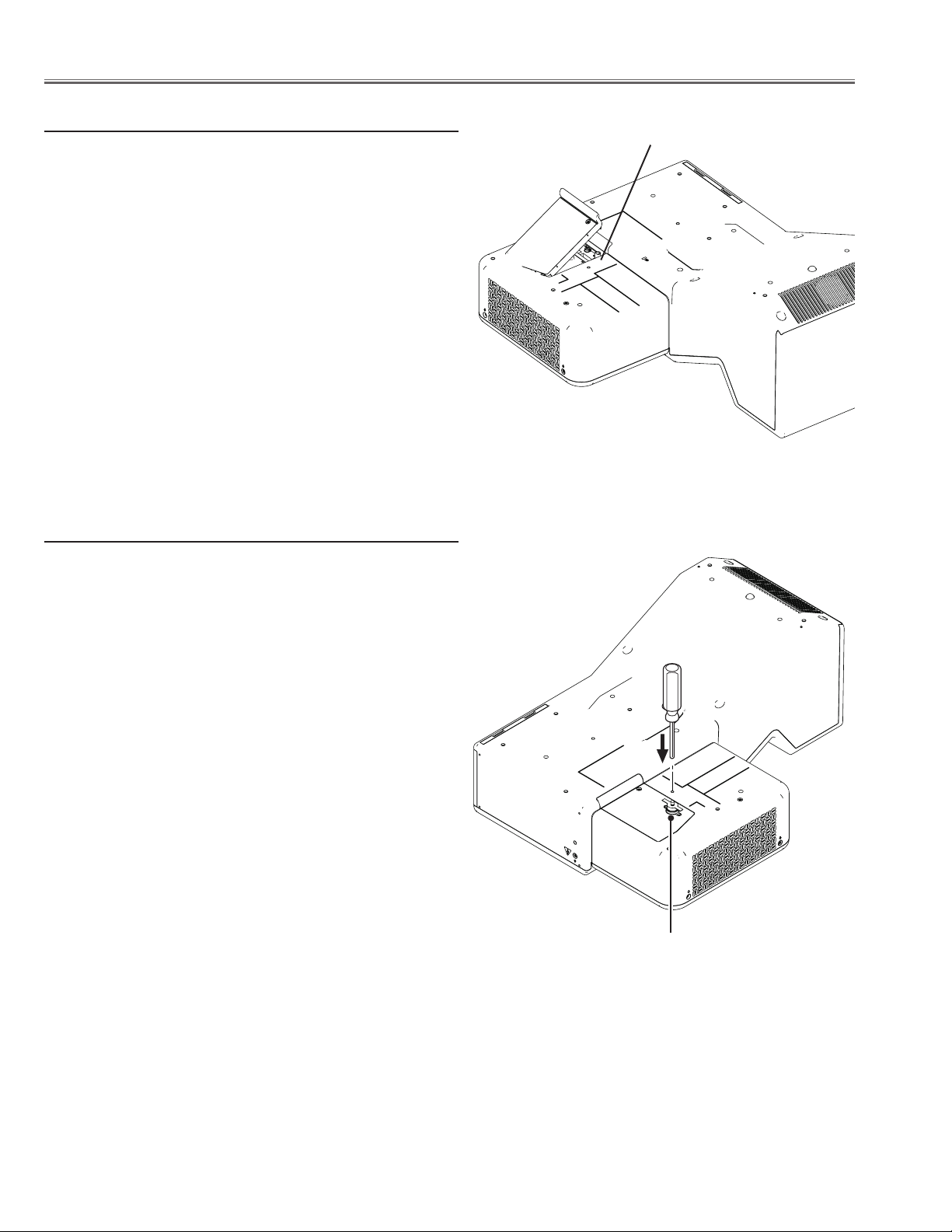
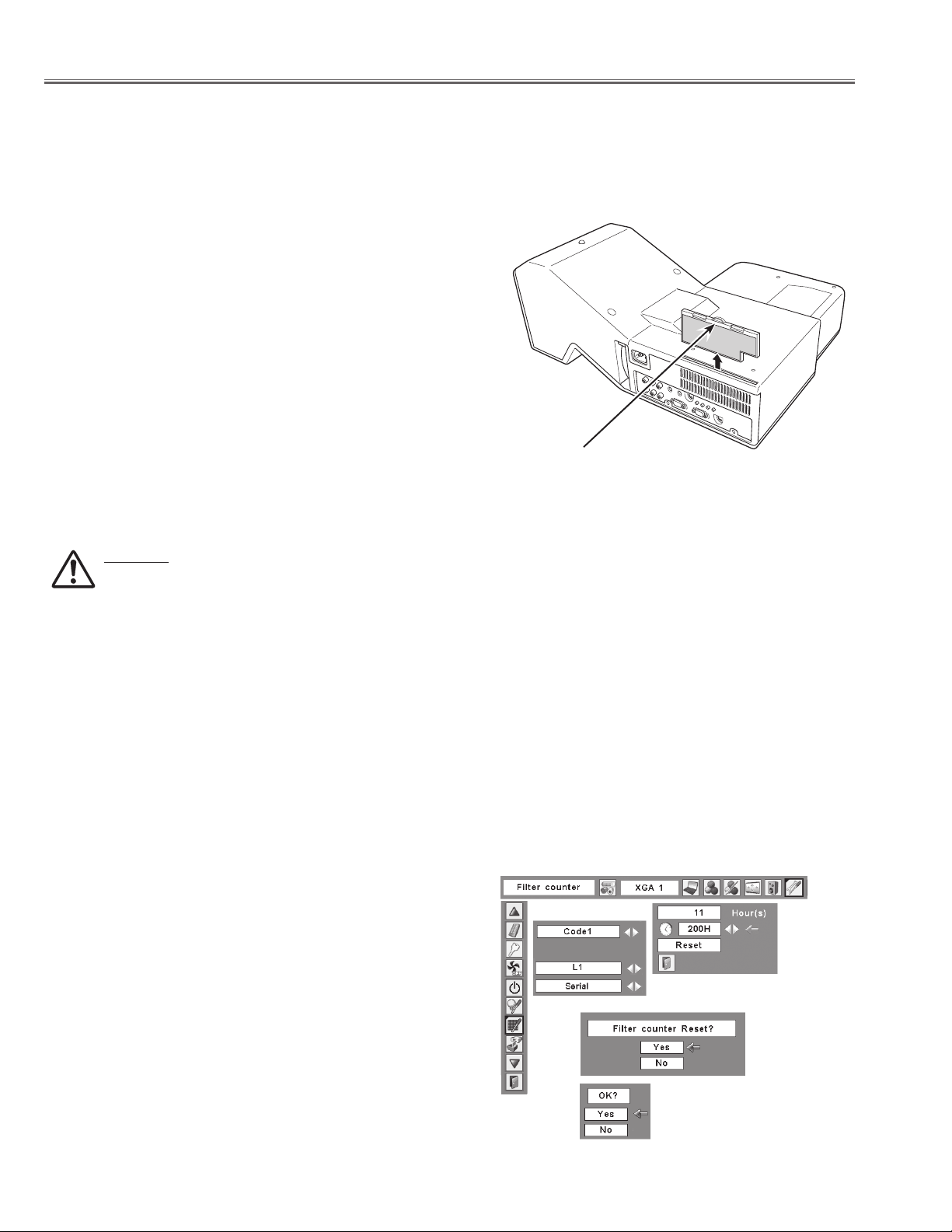
Cleaning the Air Filter ..................................................................... 8
Resetting the Filter Counter ......................................................... 8
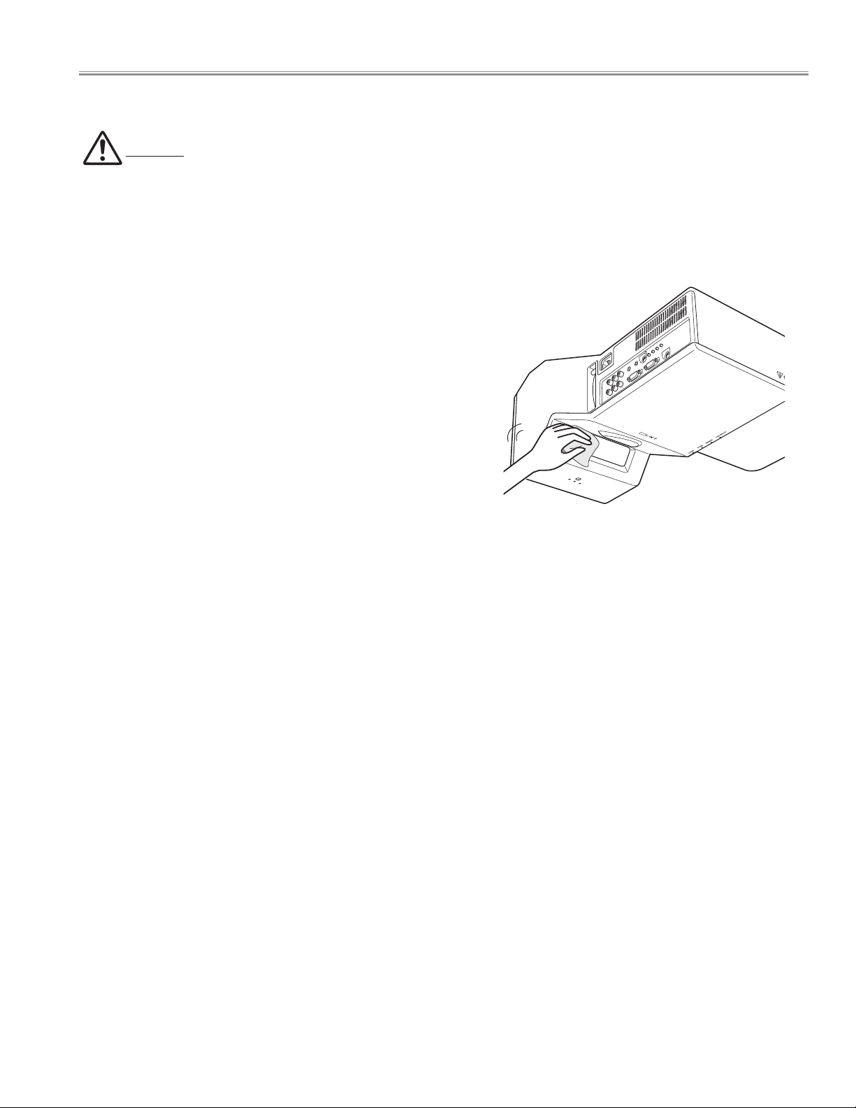
Cleaning the Projector Window .................................................. 9
Cleaning.............................................................................................10
Lamp Replacement............................................................................11
Lamp Replacement Counter ......................................................12
How to check Lamp Used Time.................................................13
Security Function Notice and Standby mode notice ............14
Security Function Disable............................................................14
Antitheft Alarm Function Disable.............................................14
Standby mode .................................................................................14
Mechanical Disassembly..................................................................15
Optical Parts Disassembly...............................................................27
Optical Parts Location and Direction ......................................33
Adjustments.........................................................................................34
Adjustments after Parts Replacement ....................................34
Optical Adjustments .........................................................................35
Contrast adjustment......................................................................35
Integrator lens adjustment.........................................................36
Relay lens-Out adjustment .........................................................37
Projection Lens focus adjustment............................................38
Electrical Adjustments..................................................................40
Service Adjustment Menu Operation .....................................40
Circuit Adjustments.......................................................................41
Test Points and Locations............................................................46
Service Adjustment Data Table .................................................48
Chassis Block Diagram......................................................................63
Chassis over view............................................................................63
System control.................................................................................64
Lamp control....................................................................................65
Audio circuit .....................................................................................66
Power supply & protection circuit............................................67
Eco-Standby mode (Sub-CPU)...................................................68
Fan control circuit...........................................................................69
IIC bus control circuit ....................................................................70
Troubleshooting .................................................................................71
Indicators and Projector Condition..........................................71
No Power ...........................................................................................72
No Picture..........................................................................................73
No Sound...........................................................................................74
Control Port Functions .....................................................................75
Scaler I/O Port Functions (PW190) ...........................................75
IC Block Diagrams...............................................................................77
Electrical Parts List .............................................................................82
Electrical Parts Location ...............................................................83
Electrical Parts List..........................................................................84
Mechanical Parts List...................................................................... 105
Cabinet Parts Location............................................................... 105
Optical Parts Location................................................................ 105
Mechanical Parts List.................................................................. 109
Diagrams & Drawings ...................................................................... A1
Parts description and reading in schematic diagram .......... A2
Schematic Diagrams ........................................................................ A3
Printed Wiring Board Diagrams.................................................... A9
Pin description of diode, transistor and IC.............................A13
Note on Soldering...........................................................................A14

- 3 -
Safety Instructions
WARNING:
The chassis of this projector is isolated (COLD) from AC line by using the converter transformer. Primary side of the con-
verter and lamp power supply unit circuit is connected to the AC line and it is hot, which hot circuit is identified with
the line ( ) in the schematic diagram. For continued product safety and protection of personnel injury, servicing
should be made with qualified personnel.
The following precautions must be observed.
Safety Precautions
1: An isolation transformer should be connected in
the power line between the projector and the AC line
before any service is performed on the projector.
2: Comply with all caution and safety-related notes pro-
vided on the cabinet back, cabinet bottom, inside the
cabinet or on the chassis.
3: When replacing a chassis in the cabinet, always
be certain that all the protective devices are installed
properly, such as, control knobs, adjustment covers or
shields, barriers, etc.
DO NOT OPERATE THIS PROJECTOR WITHOUT THE PRO
TECTIVE SHIELD IN POSITION AND PROPERLY SECURED.
4: Before replacing the cabinet cover, thoroughly
inspect the inside of the cabinet to see that no stray
parts or tools have been left inside.
Before returning any projector to the customer, the
service personnel must be sure it is completely safe to
operate without danger of electric shock.
Service Personnel Warning
Eye damage may result from directly viewing the light produced by the Lamp used in this equipment. Always turn off
Lamp before opening cover. The Ultraviolet radiation eye protection required during this servicing.
Never turn the power on without the lamp to avoid electric-shock or damage of the devices since the stabilizer gener-
ates high voltages (15kV - 25kV) at its starts.
Since the lamp is very high temperature during units operation replacement of the lamp should be done at least 45
minutes after the power has been turned off, to allow the lamp cool-off.
Product Safety Notice
Product safety should be considered when a component replacement is made in any area of the projector.
Components indicated by mark !in the parts list and the schematic diagram designate components in which safety
can be of special significance. It is, therefore, particularly recommended that the replacement of there parts must be
made by exactly the same parts.

- 4 -
Mechanical Information
Projector Type Multi-media Projector
Dimensions (W x H x D) 14.72” x 7.75” x 19.49”(374 mm x 196.8 mm x 495 mm) (Not including projections)
Net Weight 15.86 lbs (7.2 kg)
Panel Resolution
LCD Panel System 0.8” P-Si TFT Active Matrix type
Panel Resolution 1,024 x 768 dots
Number of Pixels 2,359,296 (1,024 x 768 x 3 panels)
Signal Compatibility
Color System
PAL, SECAM, NTSC, NTSC4.43, PAL-M, and PAL-N
SD/HDTV Signal 480i, 480p, 575i, 575p, 720p, 1035i, and 1080i
Scanning Frequency H-sync. 15 kHz–100 kHz, V-sync. 50–100 Hz
Optical Information
Projection Image Size (Diagonal) Adjustable from 60”to 80”
Projection Lens F 1.85 lens with f 4.83 mm with manual focus
Distance (Screen - Projector) -0.131’ – 0.265’ (-4.0 cm – 8.1 cm)
Projection Lamp 230 W
Interface
Video Input Jack RCA Type x 1
S-Video Input Jack Mini DIN 4 pin x 1
Audio Input Jacks RCA Type x 2
Component Input Jacks RCA Type x 3
Computer Input 1 Input Terminal
Analog RGB (Mini D-sub 15 pin) Terminal x 1
Computer Input 2 / Monitor Output Terminal
Analog RGB (Mini D-sub 15 pin) Terminal x 1 (In/Out switchable)
Audio Input Computer Jack
Mini Jack (stereo) x 1
Service Port Connector Mini DIN 8 pin x 1
Audio Output Jack Mini Jack (stereo) x 1 (Variable)
Audio
Internal Audio Amp 2.0 W RMS
Built-in Speaker 1 speaker, ø2.0”(50 mm)
Power
Voltage and Power Consumption AC 100–120 V (3.2 A Max. Ampere), 50/60 Hz (The U.S.A and Canada)
AC 200–240 V (1.6 A Max. Ampere), 50/60 Hz (Continental Europe and The U.K.)
Operating Environment
Operating Temperature 41˚F–95˚F (5˚C–35˚C)
Storage Temperature 14˚F–140˚F (-10˚C–60˚C)
Remote Control
Battery AA or LR6 1.5V ALKALINE TYPE x 2
Operating Range 11.5’(3.5 m) / ±90˚
Dimensions 1.9” (W) x 0.87” (H) x 5.7” (D) (49 mm x 22 mm x 145.3 mm)
Net Weight 3.53 oz (100 g) (including batteries)
Technical Specifications
●The specifications are subject to change without notice.
●LCD panels are manufactured to the highest possible standards. Even though 99.99% of the pixels are effective, a tiny fraction
of the pixels (0.01% or less) may be ineffective by the characteristics of the LCD panels.

- 5 -
■Curcuit Protections
Fuse
A fuse is located inside of the projector. When the POWER indicator
is not lightning, the fuse may be opened. Check the fuse as following
steps.
The fuse should be used with the following type;
How to replace the fuse
1. The fuse is placed on the line filter board under the main board.
Remove the cabinet top and main board. (Refer to Fig.)
2. Take the fuse off, and replace the new one with the specified type.
This projector provides the following circuit protections to operate in safety. If the abnormality occurs inside the projector, it will
automatically turn off by operating one of the following protection circuits.
Fuse Part No.: 323 025 1204
TYPE 8A 250V FUSE
LITTLE FUSE INC. TYPE 215008
Remove the 3 screws and remove the line filter board
Fuse (F601)
Line filter board

- 6 -
Lamp cover switch
The lamp cover switch (SW901) cuts off the drive signal to the
lamp circuit when the lamp cover is removed or not closed com-
pletely. After opening the lamp cover for replacing the lamp
ass’y, place the lamp cover correctly otherwise the projector can
not turn on.
Lamp cover switch (SW901)
Thermal switch
There is the thermal switch (SW902) inside of the projector to de-
tect the internal temperature rising abnormally. When the inter-
nal temperature reaches near 100˚C, the thermal switch opens to
stop the operation of the power supply circuit.
The thermal switch cannot be reset itself automatically even if
the internal temperature becomes normal. Reset the thermal
switch following to the below procedure.
How to reset the thermal switch
1. Insert the sharp tool like a screwdriver into a hole on the cabi-
net from the cabinet bottom.
2. Press the reset button on the thermal switch with the screw-
driver.
CAUTION:
Before press the reset button, make sure that the AC cord must
be disconnected from the AC outlet.
Thermal switch (SW902)
Circuit Protects

- 7 -
Circuit Protects
The projector will be automatically turned off when the internal temperature of the projector is abnormally high, or the cool-
ing fans stop spinning, or the power supplies in the projector are failed.
- If the WARNING TEMP. indicator is flashing, it may detect the abnormal temperature inside the projector. Check the follow-
ing possible causes and wait until the WARNING TEMP. indicator stops flashing, and then try to turn on the projector.
- If the WARNING indicator lights red, it may defect the cooling fans or power supply circuits. Check fans operation and power
supply lines referring to the chapter “Power supply & protection circuit” in the Chassis Block Diagram section.
Possible causes
- Air filters are clogged with dust particles. Remove dust from the air filters by following instructions in the“Air filter care and
cleaning” below.
- Ventilation slots of the projector are blocked. In such an event, reposition the projector so that ventilation slots are not
obstructed.
- Check if projector is used at higher temperature place (Normal operating temperature is 5 to 35 ˚C or 41 to 95˚F)
Warning temperature and power failure protection
The projector is shut down and theWARNINGTEMP.
indicator lights red.
When the projector detects an abnormal condition, it is auto-
matically shut down to protect the inside of the projector and
the WARNING TEMP indicator lights red. In this case, unplug the
AC power cord and reconnect it, and then turn the projector on
once again to verify operation. If the projector cannot be turned
on and the WARNING TEMP. indicator still lights red, it may defect
the cooling fans or power supply circuits.
CAUTION
DO NOT LEAVE THE PROJECTOR WITH THE AC POWER
CORD CONNECTED UNDER AN ABNORMAL CONDI-
TION. IT MAY RESULT IN FIRE OR ELECTRIC SHOCK.
Indicators
WARNING TEMP.
emit a red light
WARNING
TEMP.
WARNING
FILTER

- 8 -
■Maintenance and Cleaning
Turn off the projector, and unplug the AC power cord from
the AC outlet.
Turn over the projector and remove the air filter by pulling
the latches upward.
1
2
The air filter prevents dust from accumulating on the surface of the optical elements inside the projector. Should the
air filter become clogged with dust particles, it will reduce cooling fans’ effectiveness and may result in a buildup of
internal heat and adversely affects the life of the projector. Clean the air filter by following the steps below.
Gently clean the filter by using a brush or blower.
3
Reinstall the filter into the projector properly.
4
CAUTION
Do not operate the projector with the air filter removed.
Dust may accumulate on the optical elements
degrading picture quality. Do not put anything into the
air intake vents. Otherwise it may result in malfunction
of the projector.
RECOMMENDATION
We recommend avoiding dusty/smoky environments when you operate the projector. Usage in these
environments may cause poor image quality.
When you use the projector under dusty or smoky conditions, dust may accumulate on the lens, LCD panels, or optical
elements inside the projector degrading the quality of a projected image.
When the symptoms above are noticed, contact your authorized dealer or service station for proper cleaning.
✔Note:
•When cleaning the air filter, protect the infrared
remote receiver with a soft cloth to avoid
damaging it.
• If the filter is heavily clogged and unable to
clean, replace it with a new one. Consult your
dealer for details.
Replacement Filter Part No.: 610 335 4057
Air filter
Pull up the tab and remove.
Cleaning the Air Filter
Clean up the dust on the projector and around the air
vents.
5
WARNING: Do not wash the filter with water and
any other liquid matter. Otherwise the filter may be
damaged.
Be sure to reset the Filter counter after cleaning or replacing the filter.
Press the MENU button to display the On-Screen Menu.
Use the Point 7 8 buttons to move the red frame pointer
to the Setting Menu icon.
Use the Point ed buttons to move the red frame pointer
to Filter counter and then press the SELECT button. A
dialog box appears showing the total accumulated time of
the filter use, a timer setting option, and the reset option.
Select Reset and the “Filter counter Reset?” appears. Select
[Yes] to continue.
1
2
Resetting the Filter Counter
Filter counter
Select Reset and the “Filter
counter Reset?” appears.
Select [Yes],
then another
confirmation
box appears.
Select [Yes] again to reset
the Filter counter.
Another confirmation dialog box appears, select [Yes] to
reset the Filter counter.
3
Reset the filter counter in the Setting Menu. See “Resetting
the Filter Counter” below.
6

- 9 -
Cleaning the Projector Cabinet
Unplug the AC power cord before cleaning.
Gently wipe the projector body with a soft dry cleaning cloth.
When it is heavily soiled, use a small amount of mild detergent
and finish with the cleaning cloth. Avoid excessive use of
cleaner. Abrasive cleaners, solvents, or other harsh chemicals
might scratch the surface of the cabinet.
When the projector is not in use, put the projector in an
appropriate case to avoid dust and being scratched.
Unplug the AC power cord before cleaning.
First, remove the dust with a blower. Then gently wipe the
projection window surface. Use a cleaning paper moistened
with methyl alcohol (methanol). Avoid excessive use of cleaner.
Do not use abrasive cleaners, solvents, or other harsh chemical
cleaners to avoid damaging the projection window.
Cleaning the Projection Window
CAUTION
This projector is equipped with a projection window.
Do not rub the projection window with a hard fiber cloth or hit it with a something hard to prevent the projection
window from scratching. Do not use a chemical cleaner (liquid and solid) to avoid deteriorating the projection window.
Maintenance and Cleaning

- 10 -
Cleaning
Cleaning with air spray
1. Remove the cabinet top following to “Mechanical Disas-
semblies”.
2. Clean up the LCD panel and polarizing plate by using the
air spray from the cabinet top opening.
Caution:
Use a commercial (inert gas) air spray designed for cleaning
camera and computer equipment. Use a resin-based nozzle
only. Be vary careful not to damage optical parts with the
nozzle tip. Never use any kind of cleanser on the unit. Also,
never use abrasive materials on the unit as this may cause
irreparable damage.
After long periods of use, dust and other particles will accumulate on the LCD panel, prism, mirror, polarized glass, lens, etc.,
causing the picture to darken or color to blur. If this occurs, clean the inside of optical unit.
Remove dust and other particles using air spray. If dirt cannot be removed by air spray, disassemble and clean the optical
unit.
Disassembly Cleaning
Disassembly cleaning method should only be performed
when the unit is considerable dirty and cannot be sufficient-
ly cleaned by air spraying alone.
Be sure to readjust the optical system after performing
disassembly cleaning.
1. Remove the cabinet top and main units following to “Me-
chanical Disassemblies”.
2. Remove the optical base top following to “Optical Unit
Disassemblies”. If the LCD panel needs cleaning, remove
the LCD panel unit following to “LCD panel replacement”.
3. Clean the optical parts with a soft cloth. Clean extremely
dirty areas using a cloth moistened with alcohol.
Caution:
The surface of the optical components consists of multiple
dielectric layers with varying degrees of refraction. Never
use organic solvents (thinner, etc.) or any kind of cleanser
on these components.
Since the LCD panel is equipped with an electronic circuit,
never use any liquids (water, etc.) to clean the unit. Use of
liquid may cause the unit to malfunction.
Maintenance and Cleaning

- 11 -
When the projection lamp of the projector reaches its end of life,
the Lamp replacement icon appears on the screen and LAMP
REPLACE indicator lights yellow. Replace the lamp with a new one
promptly. The timing when the LAMP REPLACE indicator should
light is depending on the lamp mode.
Follow these steps to replace the lamp.
ORDER REPLACEMENT LAMP
Replacement lamp can be ordered through your dealer. When ordering a projection lamp, give the following
information to the dealer.
●Model No. of your projector : PLC-XE50A
●Replacement Lamp Type No.: POA-LMP139
(Service Parts No. 610 347 8791)
For continued safety, replace with a lamp of the same
type. Do not drop a lamp or touch a glass bulb! The
glass can shatter and may cause injury.
Allow a projector to cool for at least 45 minutes before
you open the Lamp cover. The inside of the projector
can become very hot.
CAUTION
Turn off the projector and unplug the AC power cord. Let
the projector cool for at least 45 minutes.
Loosen the two (2) screws that secure the lamp. Lift the
lamp out of the projector by using the handle.
1
3
Replace the lamp with a new one and secure the two (2)
screws. Make sure that the lamp is set properly. Close the
lamp cover and secure the screw.
4
Remove the screw from the lamp cover and open the
cover.
2
Connect the AC power cord to the projector and turn on
the projector.
6Reset the lamp counter.
See “Lamp Replacement Counter” on the next page.
5
Lamp Replacement
CAUTION
WARNING:
TURN OFF THE UV LAMP BEFORE
OPENING THE LAMP COVER
Indicators LAMP REPLACE
indicator
Lamp replacement icon
✔Note:
•The Lamp replacement icon will not appear when the Display
function is set to “Off”, during“Freeze”, or “No show”.
WARNING
TEMP.
WARNING
FILTER
✔Note:
•When replacing the projection lamp, protect the infrared
remote receiver with a soft cloth to avoid damaging it.
■Lamp Replacement
Lamp
Screw
Handle
Screw
Lamp Cover
Screw

- 12 -
Be sure to reset the Lamp replacement counter after the lamp is replaced. When the Lamp replacement counter is reset,
the LAMP REPLACE indicator stops lighting.
Turn the projector on and press the MENU button to
display the On-Screen Menu. Use the Point 7 8 buttons to
move the red frame pointer to the Setting Menu icon.
Use the Point ed buttons to move the red frame pointer
to Lamp counter and then press the SELECT button. The
first dialog box appears showing the total accumulated
lamp time and reset option. If you select Reset, “Lamp
replacement counter Reset?” appears. Select “Yes”to
continue.
1
2
Another confirmation dialog box appears, and select “Yes”
to reset the Lamp replacement counter.
3
This projector uses a high-pressure lamp which must be handled carefully and properly. Improper handling may
result in accidents, injury, or create a fire hazard.
●Lamp life may differ from lamp to lamp and according to the environment of use. There is no guarantee of the
same life for each lamp. Some lamps may fail or terminate their life in a shorter period of time than other similar
lamps.
●If the projector indicates that the lamp should be replaced, i.e., if the LAMP REPLACE indicator lights up, replace
the lamp with a new one IMMEDIATELY after the projector has cooled down.
(Follow carefully the instructions in the Lamp Replacement section of this manual.) Continuous use of the lamp
with the LAMP REPLACE indicator lighted may increase the risk of lamp explosion.
●A Lamp may explode as a result of vibration, shock, or degradation as a result of hours of use, as it comes to the
end of life. Risk of explosion may differ according to the environment or conditions in which the projector and
lamp are being used.
IF A LAMP EXPLODES, THE FOLLOWING SAFETY PRECAUTIONS SHOULD BE TAKEN.
If a lamp explodes, disconnect the projector’s AC plug from the AC outlet immediately. Contact an authorized
service station for a checkup of the unit and replacement of the lamp. Additionally, check carefully to ensure that
there are no broken shards or pieces of glass around the projector or coming out from the cooling air circulation
holes. Any broken shards found should be cleaned up carefully. No one should check the inside of the projector
except those who are authorized trained technicians and who are familiar with projector service. Inappropriate
attempts to service the unit by anyone, especially those who are not appropriately trained to do so, may result in
an accident or injury caused by pieces of broken glass.
LAMP HANDLING PRECAUTIONS
Lamp Replacement Counter
✔Note:
•Do not reset the Lamp replacement counter without
implementing lamp replacement. Be sure to reset the Lamp
replacement counter only after replacing the lamp.
Select “Yes,” then
another confirmation
box appears.
Select “Yes”again to reset
the lamp counter.
To reset the lamp counter, move
the pointer to Reset and then
press the SELECT button. the
“Lamp replacement counter
Reset?” dialog box appears.
Lamp Replacement

- 13 -
The LAMP REPLACE indicator will light yellow when the total lamp used time (Corresponding value) reaches 3,000 hours.
This is to indicate that lamp replacement is required.
The total lamp used time is calculated by using the below expression,
Total lamp used time (Corresponding value) = Teco + (Tnormal x 1.5)
Teco : used time in the Eco mode
Tnormal : used time in the Normal mode and Auto mode.
You can check the lamp used time following to the below procedure.
1Press and hold the ON/STAND-BY button on remote control unit for more than 20 seconds.
2The projector used time and lamp used time will be displayed on the screen briefly as follows.
Counter
Projector 450 H
Lamp
Normal 200 H
Eco 250 H
Corresponding value 550 H
Total lamp used time
Projector used time
How to check Lamp Used Time
Lamp Replacement

- 14 -
■ Security Function Notice and Standby mode Notice
This projector provides security functions such as "Key lock", "PIN code lock" and "Logo PIN code lock". When the projector has
set these security function on, you are required to enter correct PIN code to use the projector. If you do not know the correct
PIN code to the projector, the projector can no longer be operated or started. In this case, you must reset those function first
according to the resetting procedure described below and then check up on the projector.
Resetting procedure
1. Standby mode is set to "Serial".
2. Turn the projector off (In the standby mode), or in the state where lamp is on.
3. Press and hold the 7and 8 button on the remote control at the same time more than 10 seconds.
The PIN code lock and Logo PIN code lock will be reset as the initial PIN code at the factory and the Key lock function is
disabled.
Please refer to the owner's manual for further information of the security functions.
Function Description
Key lock
Locks operation of the top control or the remote control.
If the Key lock is enabled with top control lock, the projec-
tor can no longer be started.
Initial setting: Key lock function is disabled
PIN code lock
Prevents the projector from being operated by an unau-
thorized person.
Initial code: “1234”
Logo PIN code lock
Prevents an unauthorized person for changing the start-
up logo and captured image on the screen.
Initial code: “4321”
Security Function Disable
Standby mode
This function is used to change the setting of standby electricity.
Eco.............Standby electricity becomes small.
The projector’s network function will stop when controlling the projector with RS-232C.
Serial.......Standby electricity becomes large.
✔Note:
• When “Eco” is selected, several functions will be restricted.
• When “Eco” is selected, it is only possible to turn on the projector while
using the RS-232C serial port.

- 15 -
■Mechanical disassemblies
1Lamp Unit and Alarm Battery removal.
Disassemble should be made following procedures in numerical order.
Following steps show the basic procedures, therefore unnecessary step may be ignored.
Caution:
The parts and screws should be placed exactly the same position as the original other-
wise it may cause lose of performance and product safety.
The wiring method of the leads and ferrite cores should be returned exactly the same
state as the original, otherwise it may cause lose of performance and product safety.
Screws Expression
(Type Diameter x Length ) mm
T type M Type
Tapping screw Machine screw
1. Remove the screw-A(M3x8) and remove the Lamp cover.
2. Loosen the 2 screws-B and remove the Lamp uint.
3. Remove the Air Filter upward.
Lamp Cover
A
B
Lamp Unit
Air Filter

- 16 -
2Cabinet top ass'y removal.
1. Remove the 9 screws-A(M3x8) and remove the Cabinet top ass'y.
2. Remove the screw-B(T3x8), remove the R/C board, R/C pipe and remove the Decoration R/C.
3. Remove the Spacer, Decoration Inray LED and Shield top.
B
Cabinet Top ass'y
A
A
A
A
A
A
A
A
A
Cabinet Top ass'y
Shield Top
R/C Board
R/C pipe
Dec. R/C
Spacer
Dec. Inray LED
Cabinet Top
Mechanical disassemblies

- 17 -
3Main Board ass'y removal.
1. Remove the 3 screws-A(M2.5x6), screw-B(T3x8), screw-C(M4x6) and remove the Main board ass'y.
C
Main board ass'y
A
A
A
B
C
B
Mechanical disassemblies
Hook
Press this part

- 18 -
Main board ass'y
D
2. Remove the 2 screws-D(M2.5x6).
3. Remove the 3 screws-E(T3x6) and AV panel.
4. Remove the 4 nuts-F and Holder AV.
D
F
E
E
E
F
F
F
AV Panel
Holder AV
Main board
AV board
Mechanical disassemblies

- 19 -
4Exhaust Fan ass'y removal.
1. Remove the exhaust Fan ass'y(FN903, FN904) upward.
2. Remove the 2 screws-A(T3x8), remove the stopper exhaust Fan and remove the FN903, FN904.
Exhaust Fan ass'y
Exhaust Fan ass'y
A
A
Mounting exhaust duct
FN903
FN904
Stopper exhaust fan
Mechanical disassemblies

- 20 -
5Power supply ass'y removal.
1. Remove the screw-A(M3x8) and remove the Lamp connector.
2. Remove the screw-B(M2.5x6) and shield plate.
3. Remove the 2 screws-C(T3x8), remove the screw-D(T3x8) and remove the Power Supply ass'y.
Lamp connector
A
B
CC
D
Power supply ass'y
Shield plate
Mechanical disassemblies
Other manuals for PLC-XE50A
1
Table of contents