SCAC YV14-EA190 User manual

PART NO. 03349
PRINTED 7/2013
PRINTED IN USA
© 2013
Scag Giant-Vac
Division of Metalcraft of Mayville, Inc.
Congratulations on owning a Scag Giant-Vac Yard Vacuum! This manual
contains the operating instructions and safety information for your Scag Giant-
Vac Yard Vacuum. Reading this manual can provide you with assistance in
maintenance and adjustment procedures to keep your vacuum performing to
maximum efciency. The specic models that this book covers are listed on the
inside cover. Before operating your vacuum, please read all the information
enclosed.
OPERATOR’S
MANUAL
YARD VACUUM
Model: YV14-EA190

WARNING
FAILURE TO FOLLOW SAFE OPERATING PRACTICES MAY RESULT
IN SERIOUS INJURY OR DEATH.
Read this manual completely as well as other manuals that came with your vacuum.•
ALWAYS FOLLOW OSHA APPROVED OPERATION.•
Become familiar with the safe operation of the equipment, operator controls and•
safety signs.
DO NOT operate on steep slopes.•
Always travel across slopes.•
Keep all shields in place, especially the discharge chute.•
Before performing any maintenance or service, stop the machine and remove the•
spark plug wire.
If a mechanism becomes clogged, stop the engine before cleaning.•
Keep hands, feet and clothing away from power-driven parts.•
REMEMBER - YOUR YARD VACUUM IS ONLY AS SAFE AS THE OPERATOR!
HAZARD CONTROL AND ACCIDENT PREVENTION ARE DEPENDENT UPON THE AWARENESS,
CONCERN, PRUDENCE, AND PROPER TRAINING OF THE PERSONNEL INVOLVED IN THE
OPERATION, TRANSPORT, MAINTENANCE, AND STORAGE OF THE EQUIPMENT.
This manual covers the operating instructions and illustrated parts list for:
YV14-EA190 with a serial number of 004A00001 to 004A99999
Always use the entire serial number listed on the serial number tag when referring to this product.

I
Table of Contents
Table of Contents
GENERAL INFORMATIONSECTION 1 - ...................................................................................1
1.1 INTRODUCTION...........................................................................................................................................1
1.2 DIRECTION REFERENCE ...........................................................................................................................1
1.3 SERVICING THE ENGINE AND DRIVE TRAIN COMPONENTS.................................................................1
1.4 SYMBOLS ....................................................................................................................................................2
SAFETY INFORMATIONSECTION 2 - ......................................................................................3
2.1 INTRODUCTION...........................................................................................................................................3
2.2 SIGNAL WORDS ..........................................................................................................................................3
2.3 BEFORE OPERATION CONSIDERATIONS................................................................................................3
2.4 OPERATION CONSIDERATIONS................................................................................................................4
2.5 MAINTENANCE CONSIDERATIONS & STORAGE ....................................................................................5
2.6 USING A SPARK ARRESTOR.....................................................................................................................5
2.7 SPARK IGNITION SYSTEM .........................................................................................................................5
2.8 SAFETY AND INSTRUCTIONAL DECALS.................................................................................................6
SPECIFICATIONSSECTION 3 - ................................................................................................7
3.1 ENGINE ........................................................................................................................................................7
3.2 BLOWER ......................................................................................................................................................7
3.3 WEIGHTS AND DIMENSIONS .....................................................................................................................7
OPERATING INSTRUCTIONSSECTION 4 - .............................................................................9
4.1 CONTROLS AND INSTRUMENT IDENTIFICATION ..................................................................................9
4.2 INITIAL RUN-IN PROCEDURES................................................................................................................10
4.3 STARTING THE ENGINE ...........................................................................................................................10
4.4 OPERATION ...............................................................................................................................................10
4.5 HILLSIDE OPERATION..............................................................................................................................11
4.6 PARKING THE YARD VACUUM..................................................................................................................11
4.7 AFTER OPERATION ..................................................................................................................................11
4.8 REMOVING CLOGGED MATERIAL ..........................................................................................................11
4.9 VACUUM HOSE KIT (OPTIONAL ACCESSORY)......................................................................................11

II
Table of Contents
MAINTENANCESECTION 5 - ..................................................................................................12
5.1 MAINTENANCE CHART - RECOMMENDED SERVICE INTERVALS ......................................................12
5.2 ENGINE OIL ...............................................................................................................................................13
5.3 ENGINE FUEL SYSTEM ............................................................................................................................13
5.4 ENGINE AIR CLEANER.............................................................................................................................13
5.5 WHEELS.....................................................................................................................................................13
ILLUSTRATED PARTS LISTSECTION 6 - ..............................................................................14
6.1 SCAG GIANT-VAC APPROVED ATTACHMENTS AND ACCESSORIES..................................................14
NOTES..............................................................................................................................................................15
IMPELLER HOUSING ASSEMBLY..................................................................................................................16
HANDLE AND BAG ASSEMBLY .....................................................................................................................18
YARD VACUUM DECALS ................................................................................................................................20
LIMITED WARRANTY - YARD VACUUM..................................................Inside Back Cover

1
Section 1
INTRODUCTION1.1
Your Scag Giant-Vac product was built to the highest
standards in the industry. However, the prolonged life
and maximum efficiency of your vacuum depends on
you following the operating, maintenance and adjustment
instructions in this manual.
If additional information or service is needed, contact your
Scag Giant-Vac Dealer.
We encourage you to contact your dealer for repairs.
All Scag Giant-Vac dealers are informed of the latest
methods to service this equipment and provide prompt
and efficient service in the field or at their service shop.
They carry a full line of Scag Giant-Vac service parts.
- IMPORTANT -
The replacement of any part on this product
by other than the manufacturer's authorized
replacement part may adversely affect the
performance, durability or safety of this
product.
Use of other than original Scag Giant-Vac
replacement parts will void the warranty.
When ordering parts, always give the model and serial
number of your product.The serial number plate is located
on the frame next to the engine.
USE ONLY SCAG GIANT-VAC APPROVED
ATTACHMENTS AND ACCESSORIES.
Attachments and accessories manufactured by companies
other than Scag Giant-Vac are not approved for use on
this machine. See Section 6-1.
GENERAL INFORMATION
WARNING
For pictorial clarity, some illustrations and figures
in this manual may show shields, guards or plates
open or removed. Under no circumstances should
this product be operated without these devices
in place.
All information is based upon product information available
at the time of approval for printing. Scag Giant-Vac
reserves the right to make changes at any time without
notice and without incurring any obligation.
DIRECTION REFERENCE1.2
The “Right” and “Left”, “Front” and “Rear” of the machine
are referenced from the operator’s right and left when in
the normal operating position and facing the forward travel
direction.
SERVICING THE ENGINE AND DRIVE1.3
TRAIN COMPONENTS
Details regarding the service and repair of the engine
are not covered in this manual; only routine maintenance
and general service instructions are provided. For service
of these components during the limited warranty period,
it is important to contact your Scag Giant-Vac dealer or
find a local authorized servicing agent of the component
manufacturer. Any unauthorized work done on these
components during the warranty period may void your
warranty.

2
Section 1
SYMBOLS1.4
SYMBOL DESCRIPTION SYMBOL DESCRIPTION
Choke
Transmission
On/Start
Spring Tension on Idler
Off/Stop
Oil
Spinning Fan Blades
Thrown Object Hazard
Fast
Slow
Continuously Variable - Linear Pinch Point
Keep Bystanders Away
Read Operator's Manual
481039S

3
Section 2
INTRODUCTION2.1
Your vacuum is only as safe as the operator. Carelessness
or operator error may result in serious bodily injury
or death. Hazard control and accident prevention are
dependent upon the awareness, concern, prudence,
and proper training of the personnel involved in the
operation, transport, maintenance and storage of the
equipment. Make sure every operator is properly trained
and thoroughly familiar with all of the controls before
operating. The owner/user can prevent and is responsible
for accidents or injuries occurring to themselves, other
people or property.
READ THIS OPERATOR’S MANUAL BEFORE
ATTEMPTING TO START YOUR YARD VACUUM.
A replacement manual is available from your authorized
Scag Giant-Vac Dealer or by contacting Scag Giant-Vac,
Service Department at P.O. Box 152, Mayville, WI 53050
or contact us via the Internet at www.giant-vac.com. The
manual for this machine can be downloaded by using
the model and serial number or use the contact form to
make your request. Please indicate the complete model
and serial number of your Scag Giant-Vac product when
requesting replacement manuals.
SIGNAL WORDS2.2
This symbol means “Attention! Become Alert! Your
Safety is Involved!" The symbol is used with the following
signal words to attract your attention to safety messages
found on the decals on the machine and throughout this
manual. The message that follows the symbol contains
important information about safety. To avoid injury and
possible death, carefully read the message! Be sure to
fully understand the causes of possible injury or death.
SIGNAL WORD:
It is a distinctive word found on the safety decals on the
machine and throughout this manual that alerts the viewer
to the existence and relative degree of the hazard.
DANGER
The signal word “DANGER” denotes that an extremely
hazardous situation exists on or near the machine that
could result in high probability of death or irreparable
injury if proper precautions are not taken.
WARNING
The signal word “WARNING” denotes that a hazard exists
on or near the machine that can result in injury or death if
proper precautions are not taken.
CAUTION
The signal word “CAUTION” is a reminder of safety
practices on or near the machine that could result in
personal injury if proper precautions are not taken.
Your safety and the safety of others depends significantly
upon your knowledge and understanding of all correct
operating practices and procedures of this machine.
BEFORE OPERATION2.3
CONSIDERATIONS
Check the engine oil level and add oil as needed1.
to bring the level up to the FULL mark. See engine
owner's manual for oil specifications.
NEVER allow children to operate this machine. Do2.
not allow adults to operate this machine without
proper instructions.
Do not operate when children and/or others are3.
present. Keep children out of the work area and in
the watchful care of a responsible adult other than
the operator. Be alert and turn machine off if a child
enters the area.
DO NOT allow children to ride or play on the4.
machine, it is not a toy.
DO NOT operate the machine under the influence of5.
alcohol or drugs.
SAFETY INFORMATION

4
Section 2
If the operator(s) or mechanic(s) cannot read6.
English, it is the owner's responsibility to explain this
material to them.
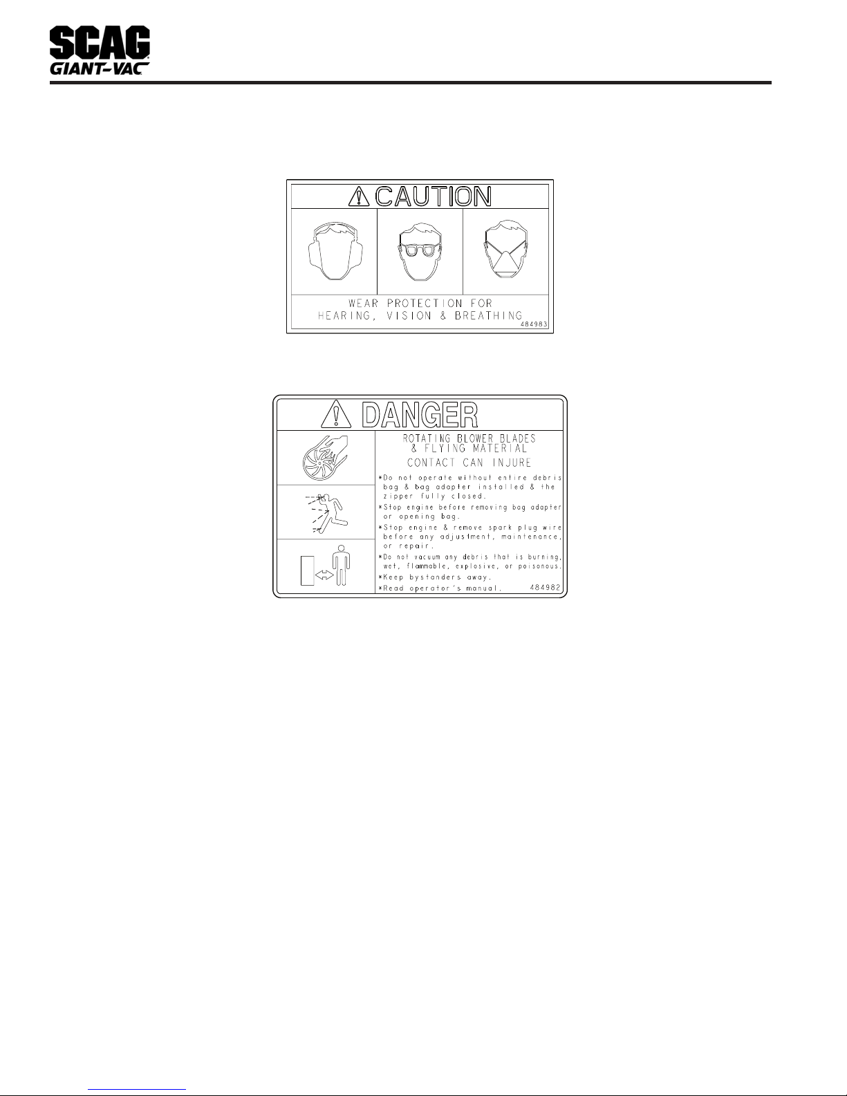
DO NOT wear loose fitting clothing. Loose clothing,7.
jewelry or long hair could get tangled in moving
parts. Do not operate the machine wearing shorts;
always wear adequate protective clothing including
long pants. Wearing safety glasses, safety shoes and
a helmet is advisable and is required by some local
ordinances and insurance regulations.
WARNING
Always wear hearing protection. Operating this
machine over prolonged periods of time can
cause loss of hearing.
Keep the machine and attachments in good8.
operating condition. Keep all shields and safety
devices in place. If a shield, safety device or decal
is defective or damaged, repair or replace it before
operating the machine.
Thoroughly inspect the area where the equipment is9.
to be used and remove all foreign objects.
Fuel is flammable; handle it with care. Fill the fuel10.
tank outdoors. Never fill it indoors. Use a funnel or
spout to prevent spillage. Clean up any spillage
before starting the engine.
DO NOT add fuel to a running or hot engine. Allow11.
the engine to cool for several minutes before adding
fuel. Never fuel indoors or inside enclosed trailers.
If fuel is spilled, do not attempt to start the engine12.
but move the machine away from the area of spillage
and avoid creating any source of ignition until the
fuel vapors have disappeared.
See Section 5.3 ENGINE FUEL SYSTEM for fueling13.
procedure.
Keep flammable objects (cigarettes, matches, etc.),14.
open flames and sparks away from the fuel tank and
fuel container. Use only approved containers.
Do not operate without the debris bag installed.15.
Check the debris bag and components frequently for16.
signs of wear or deterioration and replace as needed
to prevent injury from thrown objects going through
weak or torn spots.
Never attempt to make any adjustments while the17.
engine is running unless specifically recommended
by the manufacturer.
Check the engine mounting bolts at frequent18.
intervals for proper tightness.
OPERATION CONSIDERATIONS2.4
Know the function of all controls and how to stop1.
quickly in case of an emergency.
Do not carry passengers.2.
Do not overload the machine by attempting to chip3.
or shred any material beyond the manufacturer's
recommendation.
Do not operate on slopes if you are uneasy or4.
uncertain. Ultimate responsibility for safe operation
on slopes rests with the operator.
Exercise extreme caution when operating on slopes.5.
Keep all movements slow and gradual. Be sure of
your footing.
Do not turn on slopes unless absolutely necessary.6.
Turn slowly and downhill when possible.
Do not operate on steep slopes. Poor footing could7.
cause a slip and fall accident.
When using this machine, never direct the material8.
being collected toward bystanders or allow anyone
near the machine while in operation.
Do not operate around cars, windows, or other items9.
which could be injured or damaged by blown debris.
Before attempting to start the engine, inspect the10.
machine, debris bag, shields and safety devices
for any damage. Correct any problems before
operating.
If the vacuum ever plugs, shut off the engine, and11.
wait for all movement to stop before removing the
obstruction.
WARNING
DO NOT use your hand to dislodge the clogged
material. Use a stick or other device to remove
clogged material after the engine has stopped
running and the vacuum fan has stopped
turning.
Stop the engine when crossing gravel drives.12.
If the machine begins to vibrate abnormally, shut the13.
machine off immediately. Inspect the machine and
have repairs made before restarting.

5
Section 2
Be alert for holes, rocks, roots and other hidden14.
hazards in the terrain. Cautiously enter a new area.
Be alert for hidden hazards.
Do not operate near drop-offs, ditches or15.
embankments.You could lose your footing, balance
or drive the machine off the edge.
Use only in daylight or good artificial light.16.
Do not leave the machine unattended.17.
The machine and attachments should be stopped18.
and inspected for damage after striking a foreign
object, and damage should be repaired before
restarting and operating the machine.
Keep hands and feet away from vacuum intake and19.
outlet. Contact can injure.
CAUTION
Do not touch the engine or the muffler while the
engine is running or immediately after stopping.
These areas may be hot enough to cause a
burn.
DANGER
DO NOT run the engine inside a building or
a confined area without proper ventilation.
Exhaust fumes are hazardous and contain
carbon monoxide which can cause brain injury
and death.
Keep hands and feet away from all other moving20.
parts. Contact can injure.
Use extra care when loading or unloading the21.
machine into a truck or trailer.
Tie the machine down securely using straps, chains,22.
cable, or ropes. Both front and rear straps must be
directed down and outward from machine.
Use care when approaching blind corners, shrubs,23.
trees, or other objects that may obscure vision.
NEVER leave the machine running unattended.24.
MAINTENANCE CONSIDERATIONS &2.5
STORAGE
Do not straighten or weld the blower fan. Replace1.
damaged or failed blower fans.
Never make adjustments to the machine with the2.
engine running unless specifically instructed to do
so. If the engine is running, keep hands, feet, and
clothing away from moving parts.
Disconnect spark plug wire to prevent accidental3.
starting of the engine when servicing or adjusting
the machine. Wait for all movement to stop before
adjusting, cleaning or repairing.
Keep all nuts, bolts and screws tight, to ensure the4.
machine is in safe working condition.
Do not change the engine governor settings or5.
overspeed the engine. See the engine operator's
manual for information on engine settings.
To reduce fire hazard, keep the muffler and engine6.
free of grass, leaves, excessive grease, oil and dirt.
Park the machine on level ground.7.
NEVER allow untrained personnel to service the8.
machine.
Keep all parts in good working condition. Replace all9.
worn or damaged decals.
Use jack stands to support components when10.
required.
Let the engine cool before storing.11.
DO NOT store the machine near an open flame.12.
Shut off fuel while storing or transporting.13.
USING A SPARK ARRESTOR2.6
The engine on this machine may not be equipped with a
spark arrestor muffler. It is in violation of California Public
Resource Code Section 4442 to use or operate this
engine on or near any forest covered, brush covered or
grass covered land unless the exhaust system is equipped
with a spark arrestor meeting any applicable local or state
laws. Other states or federal areas may have similar laws.
Check with your state or local authorities for regulations
pertaining to these requirements.
SPARK IGNITION SYSTEM2.7
This spark ignition system complies with Canadian
ICES-002.

6
Section 2
SAFETY AND INSTRUCTIONAL DECALS2.8
484983
484982

7
Section 3
SPECIFICATIONS
ENGINE3.1
General Type ................................................................................................Heavy Duty Industrial/Commercial Gasoline
Brand ..................................................................................................................................................................... Subaru
Engine Model:
(Scag Giant-Vac Model YV14-EA190).................................................................................. Subaru Model # EA190V
Displacement:
Subaru EA190V.................................................................................................................................................. 189cc
Cylinders....................................................................................................................................... 1 with Cast-Iron Sleeve
Governor..............................................................................Centrifugal Flywheel Type Set At 3,600 RPM (+/- 100 RPM)
Idle Speed:
Subaru................................................................................................................................ 1,400 RPM (+/- 150 RPM)
Carburetor .........................................................................................................................................................Float Type
Fuel...................................................................................... Non-Leaded Gasoline with a Minimum Octane Rating of 87
Fuel Capacity...................................................................................................................................... 0.22 Gallon (0.85L)
Lubrication Type.......................................................................................................................... Mechanical Splash Type
Oil Capacity ............................................................................................................................................0.63 Quart (0.6L)
Starter:
Subaru.................................................................................................................................................... Recoil Starter
Ignition System...........................................................................................................Solid State Transistorized Magneto
Air Filter .................................................................................................................................................................... Foam
BLOWER3.2
Impeller Diameter .........................................................................Balanced 14" Welded Steel with Tapered Locking Hub
Number of Blades....................................................................................................................................................... 4
CFM (cubic feet / min.) ......................................................................................................................................................
Discharge .................................................................................................................................................................. Rear
WEIGHTS AND DIMENSIONS3.3
Length...........................................................................................................................................................................64"
Width ......................................................................................................................................................................26-1/4"
Height ..................................................................................................................................................... 38" up to 47-1/4"
Weight ....................................................................................................................................................................... 135#
Wheels:
(2) Front..................................................................................................................14" x 2" No-Flat w/Roller Bearings
(2) Rear ..................................................................................................................14" x 2" No-Flat w/Roller Bearings

8
Section 3

9
Section 4
CAUTION
Do not attempt to operate this machine unless
you have read this manual. Learn the location and
purpose of all controls and instruments before
you operate.
CONTROLS AND INSTRUMENT4.1
IDENTIFICATION
Before operating the yard vacuum, familiarize yourself with
all yard vacuum and engine controls. Knowing the location,
function and operation of these controls is important for
safe and efficient operation.
OPERATING INSTRUCTIONS
Engine Control (Figure 4-1).1. The engine control
is used to start, stop and control the engine speed.
Push the lever all the way forward to engage the
engine choke before pulling the recoil starter when
starting a cold engine. Once the engine starts, pull
the control back to the detent for full engine speed.
Pulling the lever back will decrease the engine
speed. Pulling the lever all the way back will stop the
engine.
Fuel Control Lever (Figure 4-1).2. Used to control
the fuel supply to the engine.
Height Control Lever (Figure 4-1).3. Used to control
the height of the vacuum intake. Lift up on the handle
bar and squeeze the height control lever to release
the locking pin. Raise and lower the handle bar until
the desired inlet height has been obtained. Release
the height control lever.
FUEL CONTROL
LEVER
ENGINE CONTROL
STOP (back)
THROTTLE
CHOKE (full forward)
HEIGHT CONTROL
LEVER
Controls and InstrumentsFigure 4-1.

10
Section 4
INITIAL RUN-IN PROCEDURES4.2
FIRST DAY OF USE OR APPROXIMATELY 20 HOURS
Change the engine oil and oil filter after the first 201.
hours of operation. (See Section 5.2.)
Check for loose hardware. Tighten as needed.2.
STARTING THE ENGINE4.3
CAUTION
DO NOT USE STARTING FLUIDS. Use of starting
fluids in the air intake system may be potentially
explosive or cause a “runaway” engine condition
that could result in engine damage and/or
personal injury.
Move the machine to a flat open area.1.
Be sure the fuel control lever, located on the left side2.
of the engine, is completely open. See Figure 4-1.
Debris bag and adapter must be fully installed to3.
actuate the interlock switch allowing the engine to
start and run.
Move the engine throttle control to about half engine4.
speed. If starting a cold engine, move the engine
control all the way forward to engage the choke.
Pull the recoil starter on the engine.5.
Allow engine to warm before operating the yard6.
vacuum.
OPERATION4.4
This yard vacuum has been designed to pick up dry
organic debris such as leaves, grass clippings, shavings
and saw dust as well as debris mixed with cans, bottles
and small amounts of sand. Vacuuming hard non-organic
material will affect the life of your machine. Sand is
abrasive and will produce wear of items including the
blower housing, impeller and bag adapter.
WARNING
DO NOT operate the machine without the entire
debris bag and bag adapter installed and the
zipper fully closed. Always wear eye, ear and
breathing protection when operating machine.
Adjust the height of the vacuum inlet. For maximum1.
debris pickup, the inlet should be as close to the
debris as possible without blocking airflow and the
engine speed should be set to "Fast".
Inspect the debris bag. It must be properly attached2.
to the machine, in good condition, clean and dry
with the top zipper fully closed. Make sure that the
accessory plug is installed into the front hole in the
vacuum nozzle.
Not all debris pick up will require that the engine3.
speed be set to "Fast". You can experiment with the
vacuum inlet height and engine speed to best suit
your conditions.
Operating in dry dusty conditions may require that4.
the engine speed be set to the "Slow" position. The
debris bag can quickly become plugged with fine
dust reducing vacuum action. A zippered vent flap
has been provided on the side of the debris bag.
It can be opened to improve air flow. Do not open
when the engine is running.
For peak performance, keep the debris bag clean5.
and do not overfill. The bag must be completely dry
before use.
WARNING
DO NOT remove the bag adapter from the machine
or open debris bag with the engine running. STOP
the engine and allow all rotation to stop.
If the vacuum intake or discharge becomes plugged,6.
shut off the engine and remove the spark plug wire.
The engine must come to a complete stop before
removing the debris bag or attempting to remove
plug from inlet or discharge area. Using a stick or
similar item, dislodge the clogged material. Then
resume normal operation.

11
Section 4
Plan how to clear a yard or parking lot to reduce7.
clearing time.
Keep vacuum intake and discharge clean.8.
Use a slow travel speed when clearing heavy or9.
large amounts of material.
HILLSIDE OPERATION4.5
WARNING
DO NOT operate on steep slopes. Poor footing
could cause a slip and fall accident. ALWAYS
FOLLOW OSHA APPROVED OPERATION.
Do not operate on slopes if you are uneasy or1.
uncertain. Ultimate responsibility for safe operation
on slopes rests with the operator.
Be sure of footing on slopes.2.
Caution must be used when operating on slopes,3.
especially when the grass is wet. Wet grass reduces
traction and control.
To prevent tipping or loss of control, keep all4.
movements on slopes slow and gradual.
Do not turn on slopes unless necessary, and then5.
turn slowly and down hill when possible.
Be alert for holes, rocks, roots and other hidden6.
hazards in the terrain. Uneven terrain could cause a
slip and fall accident.
PARKING THE YARD VACUUM4.6
Park the machine on a flat, level surface only. Do not1.
park the machine on an incline.
Pull the engine control all the way back to the OFF2.
position.
AFTER OPERATION4.7
After the engine has cooled down, wash the entire1.
machine after each use. Do not use high pressure
spray or direct the spray onto electrical components.
- IMPORTANT -
Do not wash a hot or running engine. Cold water
will damage the engine. Use compressed air to
clean the engine if it is hot.
Keep the entire machine clean to inhibit serious heat2.
damage to the engine.
DANGER
To avoid injury from burns, allow the engine
to cool before removing the fuel tank cap and
refueling.
REMOVING CLOGGED MATERIAL4.8
DANGER
ROTATING FAN BLADES
NEVER PUT YOUR HANDS INTO THE VACUUM
INTAKE OR DISCHARGE FOR ANY REASON!
Shut off the engine, remove the spark plug wire
and only then use a stick or similar object to
remove material if plugging has occurred.
If the vacuum intake or discharge becomes plugged,1.
shut off the engine and remove the spark plug wire.
The engine must come to a complete stop before
removing the debris bag or attempting to remove
plug from inlet or discharge area. Using a stick or
similar item, dislodge the clogged material. Then
resume normal operation.
VACUUM HOSE KIT (OPTIONAL4.9
ACCESSORY)
A vacuum hose kit is available that plugs into the front of
the yard vacuum. The hose allows easy access for hard
to reach places. Contact your authorized Scag Giant-Vac
dealer for information.

12
Section 5
MAINTENANCE CHART - RECOMMENDED SERVICE INTERVALS5.1
HOURS
PROCEDURE COMMENTS
BREAK-IN
(FIRST 10) 8 20 50 100 200 500
X Check all hardware for tightness
X Check engine oil level See engine operator's
manual
X *Clean vacuum
X Check condition of interlock switch See Section 4.3
X Check condition of debris bag
X Check condition of fan blades
X Change engine oil and filter See engine operator's
manual
X *Clean air filter element See engine operator's
manual
X Check condition of fuel lines
X Check all hardware for tightness
X Change engine oil See engine operator's
manual
X *Clean air cleaner element See engine operator's
manual
X *Clean Fuel Cup See engine operator's
manual
X *Replace engine air filter See engine operator's
manual
X Clean and Adjust Spark Plug See engine operator's
manual
X Replace Spark Plug See engine operator's
manual
* Perform these maintenance procedures more frequently under extreme dusty or dirty conditions.
MAINTENANCE

13
Section 5
Never remove the gas cap or add fuel with the4.
engine running. Allow the engine to completely cool
before fueling.
Never fuel the machine indoors or in an enclosed5.
trailer.
Never store the machine or fuel container where6.
there is an open flame, spark or pilot light such as on
a water heater or other appliances.
Never fill containers inside a vehicle or on a truck7.
or trailer bed with a plastic liner. Always place
containers on the ground away from your vehicle
before filling.
Remove the machine from the truck or trailer and8.
fuel on level ground. If this is not possible, then refuel
the machine with a portable container, rather than
from a gasoline dispenser nozzle.
Keep the nozzle in contact with the rim of fuel tank9.
or container opening at all times until fueling is
complete. Do not use a nozzle lock-open device.
If fuel is spilled on clothing, change clothing10.
immediately and wash affected skin.
Replace gas cap and tighten securely.11.
ENGINE AIR CLEANER5.4
A. CLEANING AND/OR REPLACING AIR
CLEANER ELEMENT
For any air cleaner, the operating environment dictates
the air cleaner service periods. Inspect and clean the
air cleaner element after every 50 hours of operation or
monthly, whichever occurs first and replace the element if
required or every 200 hours. Refer to the Engine Operator’s
Manual furnished with this vacuum for instructions.
- NOTE -
In extremely dusty conditions it may be necessary
to check the element once or twice daily to prevent
engine damage.
WHEELS5.5
Check the condition of wheel assemblies after 8 hours of
operation or daily.
ENGINE OIL5.2
A. CHECKING ENGINE CRANKCASE OIL LEVEL
The engine oil level should be checked after every 8 hours
of operation or daily as instructed in the Engine Operator’s
Manual furnished with this vacuum.
B. CHANGING ENGINE CRANKCASE OIL
After the first 20 hours of operation, change the engine
crankcase oil and replace the oil filter. Thereafter,
change the engine crankcase oil after every 100 hours of
operation or bi-weekly, whichever occurs first. Refer to the
Engine Operator’s Manual furnished with this vacuum for
instructions.
ENGINE FUEL SYSTEM5.3
DANGER
To avoid injury from burns, allow the mower
to cool before removing the fuel tank cap and
refueling.
A. FILLING THE FUEL TANK
Fill to the top of the fuel filter screen (approximately 1/4
gallon) at the beginning of each operating day. Do not
overfill. Use clean, fresh unleaded gasoline with a minimum
octane rating of 87 and a maximum of 10% Ethanol.
DO NOT use E85 Fuel. Using E85 Fuel will cause severe
damage to the engine.
To avoid personal injury or property damage, use extreme
care in handling gasoline. Gasoline is extremely flammable
and the vapors are explosive.
Extinguish all cigarettes, cigars, pipes and other1.
sources of ignition.
Use only an approved gasoline container.2.
When filling the fuel tank, always use the fuel filter3.
screen.

14
Section 6
SCAG GIANT-VAC APPROVED ATTACHMENTS AND ACCESSORIES.6.1
Attachments and accessories manufactured by companies other than Scag Giant-Vac are not approved for
use on this machine.
ILLUSTRATED PARTS LIST

15
Section 6
NOTES

16
Section 6
A
COIL
A
1
2
5
5
3
5
4
76
8
41
31
30 13
11 12
9
10
16
15
15
17
18
19
20
22
23
9
24 21 23
9
25
27
28
15
42
26
29
29
30
30
31
31
32
32
35
33
34
36
37
38
39
40
34
35
37 36
14
IMPELLER HOUSING ASSEMBLY
Table of contents