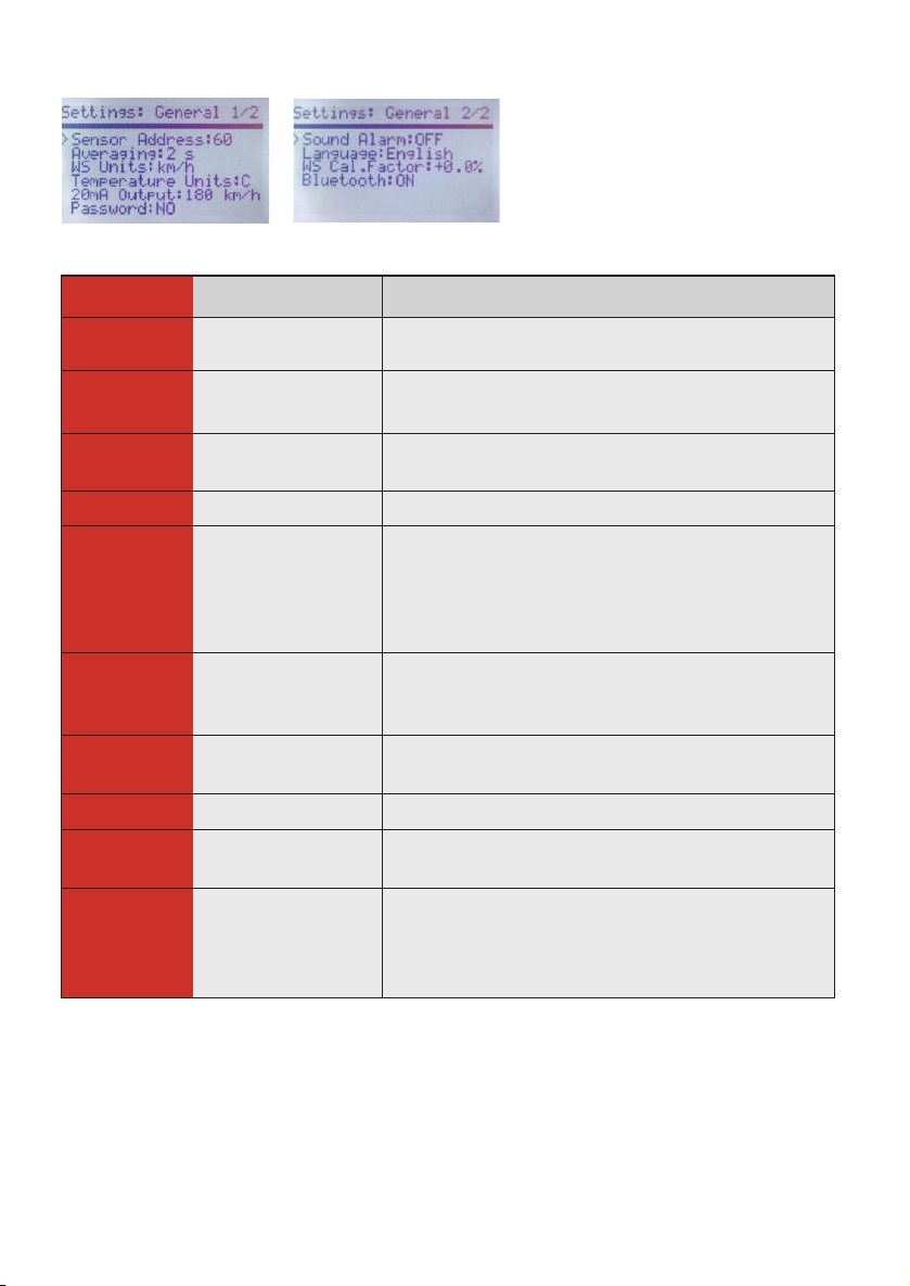
Factory default Settable range Description
Sensor address Enclosed sensor 1…255 Set the sensor address of your
Wind speed sensor
Averaging period 2 sec 2/10/30 sec Averaging period for showed
wind speed
Wind speed unit km/h m/s, km/h, mph,
knots Unit of displaying wind speed
Temperature unit ° C ° C or ° F Unit of displaying Temperature
20 mA output 180 km/h 10…50 m/s
Wind speed at 20 mA output
4mA = 0 km/h
20 mA = seted value wind speed
* applicable only at model with
additional 4-20 mA output
Password No No
Yes:0000…9999
Activation of password
protection and setting of
password
Sound alarm On On/Off Switching sound alarm ON and
OFF
Language English English/French Language selection
Wind speed
calibration factor +0.0% Calibration factor for wind speed
(-15,0 ...+15,0% in 0,5% steps)
Bluetooth On On/Off
Power ON/OFF Bluetooth
transmitter
* applicable only at WSM
W410XB model
General Settings