-4-
Installation Instructions
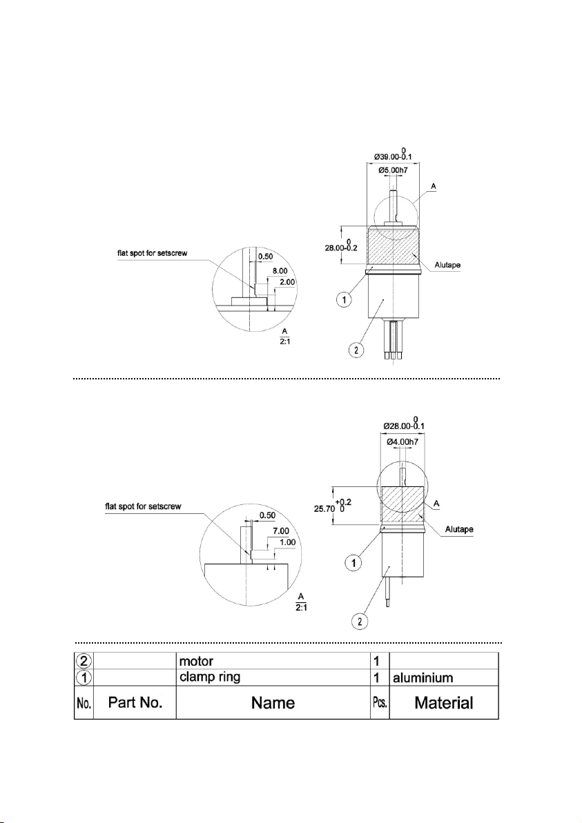
Drawing #1 (Assembly):
DS-30-AXI HDS:
DS-51-AXI HDS:
Information on Drawing #1:
• Prepare the motor according to drawing #3 and the
corresponding instructions (p.7).
• Insert the motor into the stator.
• Before, please apply some copper paste on the wrapped part of
the motor, so that a proper heat conduction between the motor
case and the stator unit can be guaranteed.
• Screw the motor and the stator together according to drawing #1.
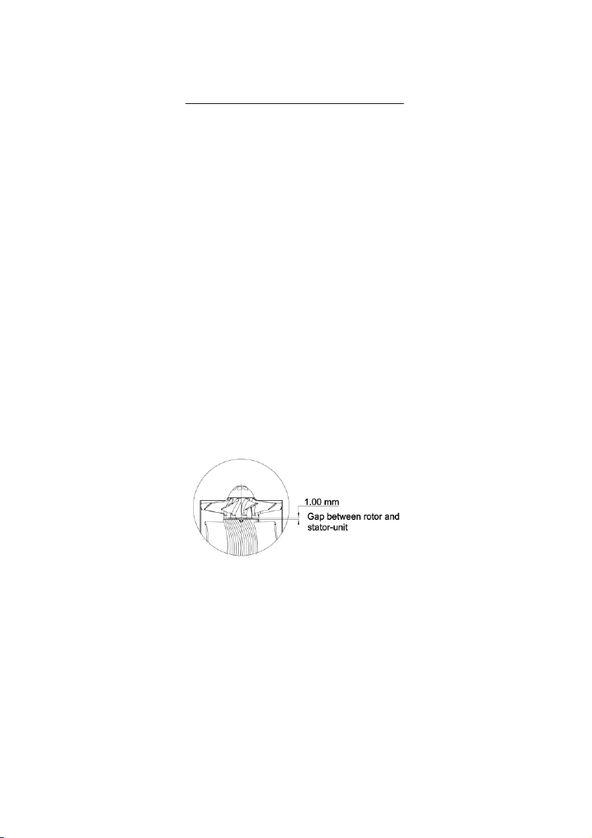
• The gap between stator and rotor is adjusted by appropriate
spacers, which will be removed after screwing (e.g. feeler gauge
stock).
•Put the rotor on the motor shaft according to drawing #1 and fix it
with 3 setscrews (pos. 3, drawing #1). In order to do this, please
put the appropriateAllen wrench in the existing bore.
• When fixing the screws, take care that the rotor and the motor
shaft don't stick together because of the screw lock.
• Don't tighten all setscrews at once, but build up fixture step-by-
step all round until you tighten all setscrews in the last round. By
doing this, a central position of the rotor on the motor shaft can be
guaranteed.
• Pay attention to the distance between rotor and stator, and also
to the position of a setscrew above the flat spot of the motor
shaft.
• Please rotate the integrated rotor by hand once. The rotor should
run smoothly (except for the cogging of the motor) and should not
exhibit any grinding noise.
• Please check the evenness of the gap between the rotorblades in
the backlight.
-5-
Drawing #2: