8 Product description
2 Product description
2.1 Performance features
The AM-T100 is a ToF camera with an image rate of up to 60 fps and a
resolutionof640x480pixels.Withaeldofvisionof67"x51"andhigh-
performance IR illumination, it can detect objects within a range of up to 6
metres1).
ThecameraisconguredusingtheCONSAM-Tapplicationsoftware,which
allowsforcreationandmonitoringofthecomplex3Dzones.Ifthecamera
detectsobjectswithinthesezones,digitaloutputsareswitched.Inaddition,
digitalinputscanbeusedtoswitchbackandforthbetweendierent3Dzones.
The AM-T100 can also supply image data for common image processing
software via the standardised GigE Vision and GeniCam interfaces. The
integratedSDKallowssoftwaredevelopersandintegratorstocongurethe
cameraandcreatecustomer-specicsoftwareapplications.
1) Depending on the remission properties of the target objects, a range of up to 30 m can be
achieved.
2.1.1 CONSAM-T application software
The CONSAM-T application software for Windows is used for camera
conguration.Thesettingsaresavedinaprojectleandtransferredto
the camera. A detailed description can be found in chapter 6 “CONSAM-T
application software user interface” from page 30.
2.1.2 AM-T100 OS operating system
The AM-T100 OS is the operating system that is pre-installed on the camera,
that runs on the camera autonomously and that can be called via a browser.
A detailed description can be found in chapter 7 “AM-T100 OS operating system
user interface” from page 53.
2.1.3 System requirements
The following system requirements apply to operation of the AM-T100 camera
and the CONSAM-T application software:
– 2 GB free disc space
– 1 x Ethernet 100/1000 MBit/s – RJ45
– Windows 10 as of version 21H1
– Optional: PoE-capable switch or PoE injector, standard IEEE 802.3bt
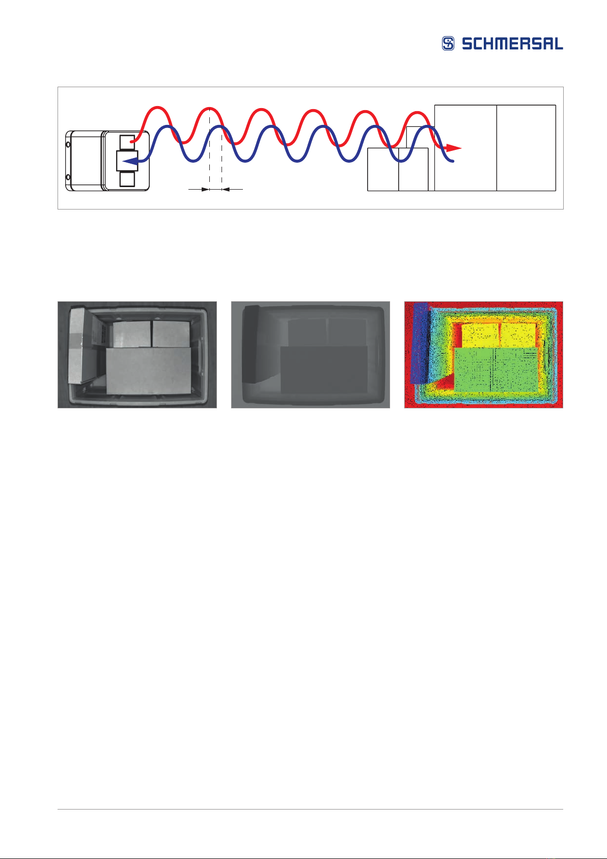
2.2 Mode of operation
TheAM-T100ToFcameraworksaccordingtotheindirecttimeofight
measurement principle, whereby the camera emits a continuous beam of
modulated light and measures the phase shift between the emitted and
reectedlight.Thisphaseshiftisusedtodeterminethedistancebetweenthe
sensorandthereectingobject.Thegreaterthephaseshift,thefartheraway
the object. The camera can then calculate the distance travelled by the light and
thus determine the distance between the camera and the object. The phase
shift is determined for each individual pixel in the image.