Scotsman cCool 37FF User manual

INSTALLATION AND
SERVICE MANUAL
37FF
INTEGRAL & WATER COOLED
SODA CIRCUIT COOLER
CARBONATOR
CCOOL SODA CIRCUIT COOLER
1

INSTALLATION INSTRUCTIONS FOR
INTEGRAL & WATER COOLED UNITS
NOTE: The unit should be installed and serviced by a suitably trained person.
NOTE: Sealed plugs may be fitted to new units.
1. Unpack the unit from its transportation packing and visually check for any signs of damage.
2. Site the unit in a convenient location in the cellar or room on a level surface where it is to be
located and make sure that a mains electricity supply is within 2 meters and in an area allowing
free circulation of air. The unit should be fitted to the following electrical supply
CCOOL 37 ----- 240v AC 30 amp solator box nstalled w th a su table 30 amp c rcu t
breaker or fuse l nk.
3. If the unit is a water cooled version, the glycol module and heat dumps must be installed and
connected as detailed in the GLYCOL MODULE AND HEAT DUMP INSTALLATION
INSTRUCTIONS of this manual , before commissioning the complete system.
. Connect the dispense head to the unit using suitable fittings and python, referring to the
connection diagram on the lid of the cooler and those supplied with the dispense head.
5. Remove the top cover and connect a mains water supply of 50psi / 60psi to the water pump inlet
labelled ‘WATER IN’, at the rear of the unit.
6. Connect all products to unit as labelled.
7. Connect CO2 gas supply (80psi - 90psi) to the cooler using the bulkhead fitting labelled ‘CO2 IN’
8. Fill the water bath with fresh clean COLD water until the overflow level is reached.
9. Connect unit to the mains electricity supply (do not turn on yet).
10. Turn on the CO2 supply and vent the carbonator bowl using the relief valve located on the top.
Additionally operate the dispense valve until the air in the python system is purged.
11. Turn on the mains water supply.
12. Check for obvious leaks and rectify before proceeding any further.
13. Ensure that the soda recirculation pump is disconnected / switched off.(See switch panel
operation on page 2)
1 . Switch on the unit at the mains power supply and allow ice bank to build, the dispense system to
prime and fill with carbonated water and the cooling system to prime. If the carbonator overtime
indicator comes on at any time during this process, reset by operating the carb reset switch.
(see switch panel operation on page 2)
15. If the unit is a water cooled version , ensure that the glycol lines prime correctly and that the
glycol module is topped up to the correct level.
16. Prime dispense head by operating the valves and ensure all pockets of CO2 are removed from
system.
17. Reconnect / switch on the soda pump.
18. Operate dispense valves until syrup is dispensed from valves.
19. Refit the top cover to the base unit.
2

20. The dispense head can now be brixed and the system will be ready to use.
CCOOL 37FF SWITCH PANEL OPERATION
ELECTRICAL SWITCHES
CARBONATOR RESET --- This switch resets the carbonator ill pump(s) i they have timed out or are
over temperature due to a ault condition.
REFRIGERATION ON/OFF------- This switch isolates the re rigeration system
SODA ON/OFF----------------- This switch isolates the dual soda recirc pumps
CARB PUMP ON/OFF--------- This switch isolates the dual carbonator pumps
HEAT DUMP AND GLYCOL MODULE INSTALLATION - WATER COOLED UNITS
HEAT DUMP - GENERAL GUIDELINES
1. It is important that the heat dump is sited correctly to enable it to work efficiently. The guidelines
below should be adhered to wherever possible.
2. Ensure the unit is sited on an outside wall (preferably non south facing) in the correct orientation
out of direct sunlight.
3. Ensure there are no other heat sources, i.e. a condensing unit or another heat dump, in the
immediate vicinity, where hot air may be re-circulating.
. Use the recommended tubing (15mm O/D, 10mm I/D Special EVA) to connect the base unit to
the heat dump. Do not use PVC braided tube, as this is not compatible with glycol and will
degrade over a period of time.
3
∅ MAINS ELECTRICAL SUPPLY SWITCH
∅ REFRIGERATION SWITCH
∅ CARBONATOR PUMP SWITCH
∅ SODA RECIRC PUMP SWITCH

5. Do not exceed the recommended distance and lift from the base unit to the heat dump of 9M
Lift, 0M Run.
6. The heat dump must be connected using a minimum of 1.5mm two core cable. If a smaller
cable is used, a voltage drop will occur which may cause the fan motor to run at a reduced
speed.
7. If the unit is to be installed inside a building or room, ensure that there is adequate ventilation
within the room to enable the heat to be dissipated effectively. Temperatures within the room
should not exceed 0 o C
8. Do not kink the flow and return tubes which would restrict the coolant flow.
9. Do not insulate the flow and return lines.
10. The flow and return lines must not be strapped together, as heat transfer between the two will
effect the system performance.
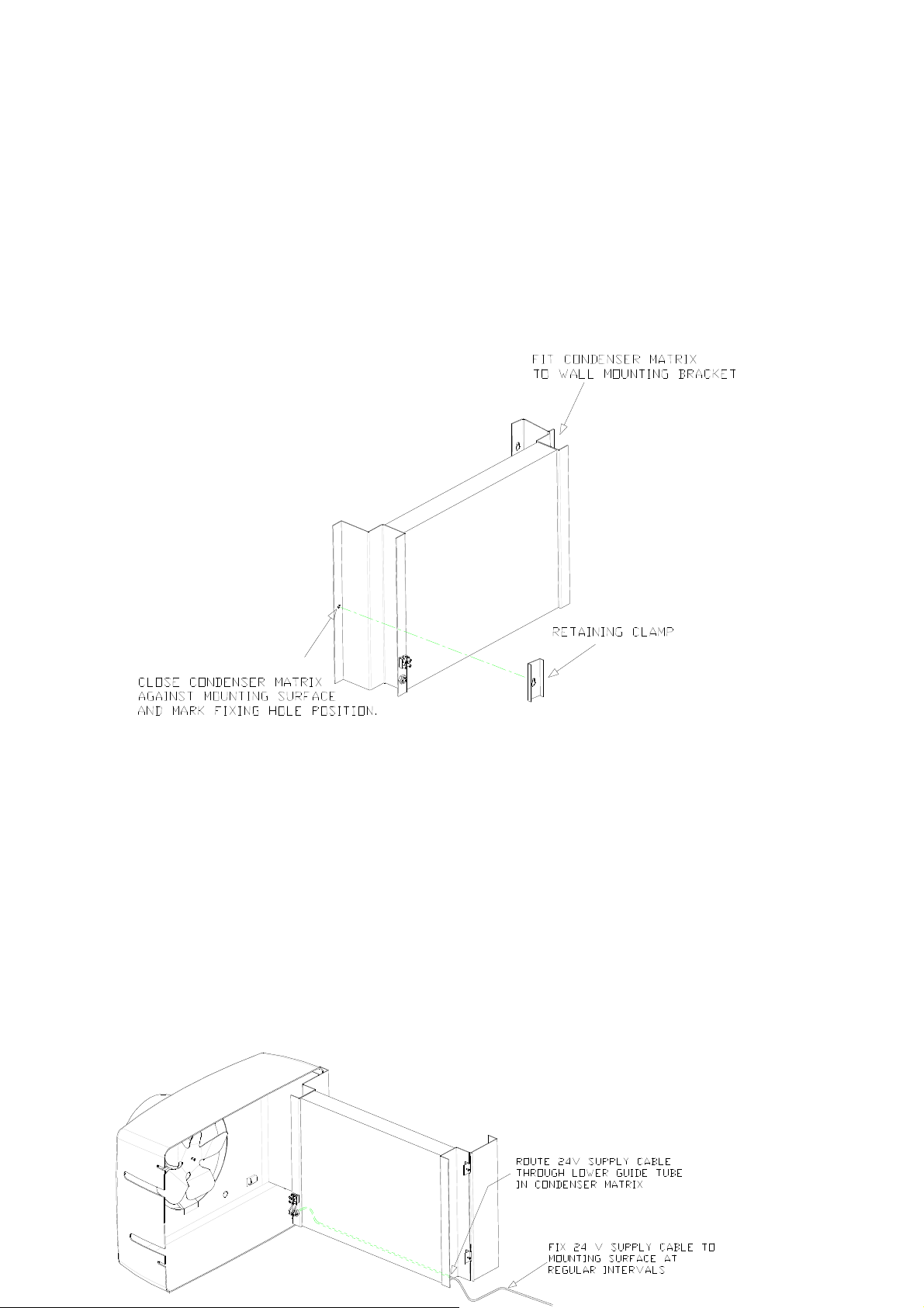
11. Ensure that the heat exchanger matrix of the heat dump is kept clean and free from
obstructions. It is recommended that it should be cleaned with a soft brush at regular intervals.
12. To enable the heat dump to be mounted on a flat surface, a floor standing mounting kit is
available as an option. (Order part number 09-0203-01)
GLYCOL MODULE INSTALLATION INSTRUCTIONS
1. Site the glycol pump module within 2 meters of the base unit and using suitable wall fixings,
secure the module to a wall.
2. Connect the glycol module’s power supply to the 2 0V power outlet socket on the base unit.
(DO NOT SWITCH ON YET)
3. Using Cobracol tubing, connect the ‘COOLANT FLOW’ from the glycol module to the
‘COOLANT IN’ on the base unit.
. Again using Cobracol tubing connect the ‘COOLANT OUT’ from the base unit to the ‘FLOW’ on
the first heat dump. Connect the ‘RETURN’ on heat dump to the ‘FLOW’ on the second heat
dump. Connect the ‘RETURN’ of the second heat dump to the ‘COOLANT RETURN’ on the
glycol module to complete the circuit.
5. Finally, connect the 1.5mm twin wire coming from the heat dumps to the 2 v outlet sockets on
the glycol module using the two pin plug supplied with the glycol module. It does not matter
which way the wires are connected as they are not polarised.
6. Ensure the lines are correct and secured neatly and free from kinks.
7. Fill the glycol module reservoir tank with a quantity of coolant mixed 30% glycol to 70%
water, ensuring a quantity remains for topping up the system when priming.
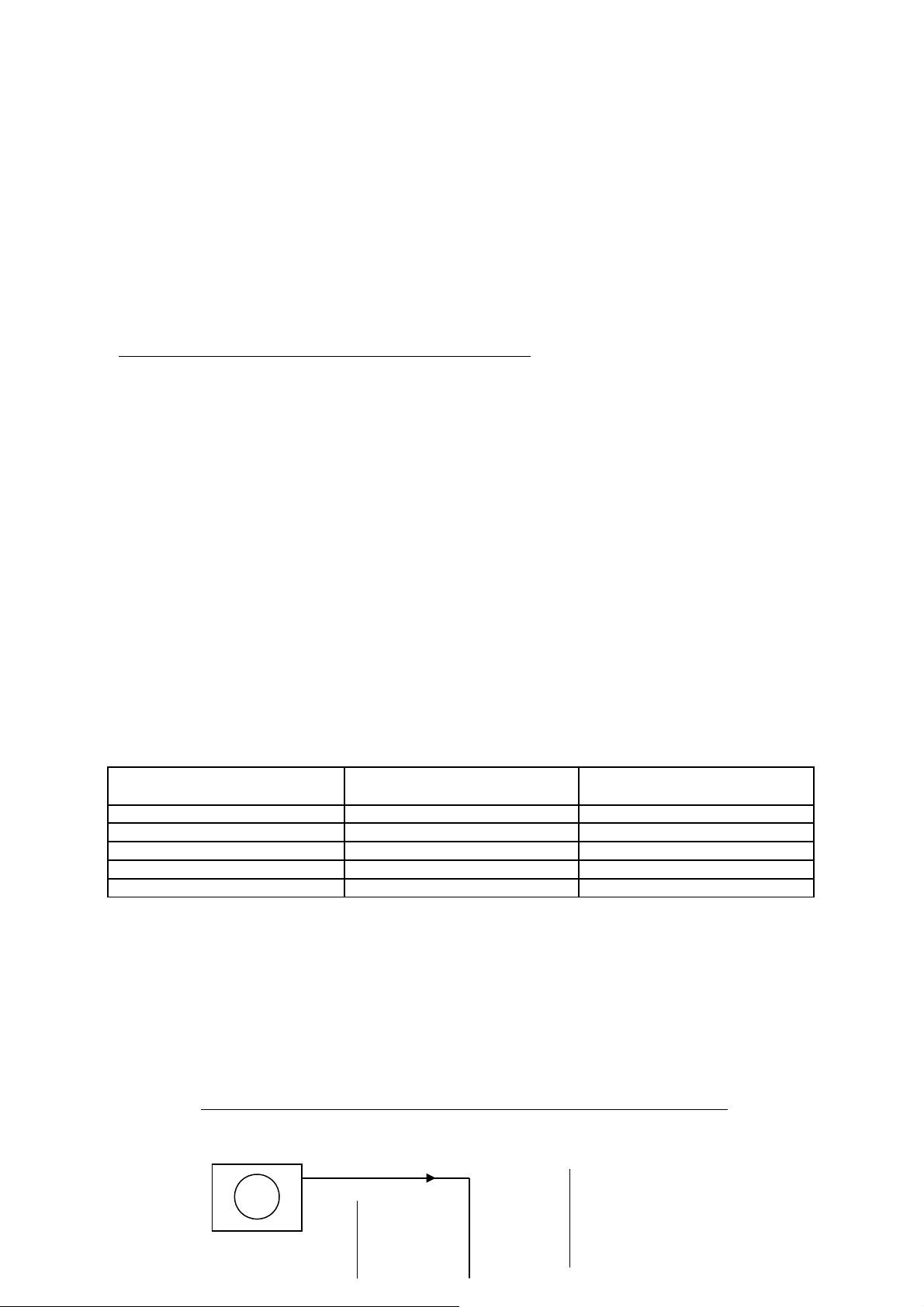
The following table should be used as a guideline for the volume of coolant for varying
installations.
NOTE: Max mum L ft = 9M Max mum Run = 40M
DISTANCE FROM BASE UNIT
TO HEAT DUMP
APPROX. VOLUME OF
GLYCOL
APPROX. VOLUME OF
WATER
5 METERS .25 LITRES 8.25 LITRES
15 METERS .5 LITRES 9.0 LITRES
20 METERS .75 LITRES 9.25 LITRES
30 METERS 5.0 LITRES 10.0 LITRES
0 METERS 5. LITRES 10.6 LITRES
8. Upon switching the unit on, the pump in the glycol module will start together with the heat dump
fans.
As the system primes, the level will drop in the coolant header tank. Keep topping
this up until the system is full, there are no air locks and that coolant is returning freely into
the header tank. If the system trips out on the pressure switch whilst priming, this will have to
be reset before the system can start again.
WATER COOLED UNIT - EQUIPMENT CONNECTION SCHEMATIC
4
BASE UNIT
GLYCOL
MODULE
2 v Supply
2 0v Mains Supply

WARNING
All water cooled units are fitted with a MANUAL RESET pressure switch to protect the system.
If a fault occurs it is likely to be one of the following:-
1. Low water \ glycol level , Coolant leak, Blockage within cooling system .
2. Component failure:- Heat dump fan motor, Water pump, 2 v Transformer, wiring fault.
If the fault persists, it should e rectified efore further operation.
HEAT DUMP INSTALLATION INSTRUCTIONS
NOTE: The unit should be installed and serviced by a suitably trained person.
Unpack the unit from its transportation packaging and visually inspect for signs of damage.Site the
dump in a convenient location, preferably in a non-heat sensitive and shaded areaon the outside of
the building. If it cannot be installed outside, ensure that the area is free from other heat sources and
is adequately ventilated to prevent heat build up from the hot exhaust air from the heat dump.
In either situation the heat dump should be sited to allow free circulation of air.
The maximum recommended height of the heat dump above the cooler is 10 meters.
F tt ng
Remove the wall mounting bracket from the assembly, (mounted on lift off hinges).
Slacken the two fixing screws securing the cover/fan assembly to the condenser matrix ,
swing the cover open and lift off the assembly.
5
HEAT
DUMPS
2 0v Supply
= Coolant Flow

With reference to the attached drawing drill the surface onto which the heat dump is to be fitted at
the stated mounting hole centers ensuring that adequate clearance is allowed around the heat dump
to allow future access for cleaning.
Note - the wall mounting bracket can be used as a guide for marking its hole centers . Ensure that
the wall mounting bracket is mounted squarely to ensure level movement of the condenser matrix
when fitted.
Either mark the position of the third mounting screw at the time of marking the wall mounting bracket
position, or after fitting the wall mounting bracket hang the condenser matrix on, close against the
mounting surface and mark the fixing position.
Note - the third fixing screw will pass through the hole in the condenser matrix. The retaining clamp
is fitted over the screw which can then be tightened to retain the condenser matrix.
Connect the flow and return pipework from the glycol module and base unit to the fittings on the heat
dump labeled “FLOW” and “RETURN” and secure the pipes to the mounting surface so that the
weight of the pipes is not being carried on the heat dump fittings.
Note - Do not kink the pipework as this will restrict coolant flow.
Do not insulate the pipework. (Pipework mounted on an exterior surface may be insulated if
it is felt that due to extreme conditions freezing may occur).
Do not strap the flow and return pipes together as heat transfer between the two will effect
the systems performance.
Route a twin core 2 volt supply cable (1.5mm csa) through the lower guide tube and then through
the strain relief grommet positioned below the two way terminal block on the condenser matrix.
Note - The wires are not polarised and may be fitted either way round.
Ensure that the amount of cable entering through the main cover is not excessive and cannot
become entangled in the fan blade. Tighten the strain relief grommet to support the cable . This
should not be the only means of support for the cable, therefore fix back to the mounting surface at
regular intervals along the cable length.
6

After the condenser matrix is fully fitted to the mounting surface, hang the cover/fan assembly onto
its hinges.
With the cover/fan assembly open, connect the wires from the fan to the terminal block .
Note - Ensure that the wiring from the fan is routed through the plastic clip provided to prevent the
possibility of the wires becoming entangled in the fan blade.
Connect the wiring and the Pipework to the cooler following the instructions supplied with the cooler.
Recommended mater als for heat dump to cooler connect ons.
Pipework - 15mm OD x 10mm ID COBRACOL tubing.
Cable - 1.5 mm sq., 2 core white PVC covered (no earth)
Insulation tubing - 3/8" or 1/2" ID
Use of the equ pment.
This unit is intended for use in conjunction with cooling units manufactured by Scotsman
Beverage Systems Ltd.
It is designed to be connected at the end of the water/glycol recirculation lines as a means
of removing heat from the cooling system.
There are NO other recommended uses for this unit.
DISMANTLING DECOMMISSIONING PROCEDURE
a. Isolate the unit from the Base cooler or Glycol module electricity supply.
b. Disconnect the recirculating coolant inlet and Outlet pipes.
ADJUSTMENTS MAINTENANCE REQUIREMENTS
7

It is not recommended that the end user makes any adjustments or carries out any maintenance
other than :
a. Check the mains lead and plug visually for condition.
b. Check the unit and its pipework for any evidence of leaks visually.
c. It there is any accidental spillage of liquid onto the unit isolate the Base Coolers
mains electricity supply before cleaning up / removing the spillage.
NOTE: THERE ARE NO USER SERVICEABLE PARTS.
CORRECT SAFE HANDLING
Handling of this unit offers no specific hazard.
Unit weight 9 kgs (20 lbs) dry.
METHODS OF CLEANING
NOTE: DO NOT USE A WATER OR STEAM HOSE TO CLEAN THE UNIT WHILST STILL
INSTALLED.
NOTE: IT IS IMPORTANT THAT ALL THE VENTS AND GRILLS ARE KEPT CLEAR (Including
Condenser grills where applicable).
NOTE: PERSONAL PROTECTIVE EQUIPMENT SHOULD ALWAYS BE USED.
Tw ce Annually: By a competent Serv ce Ma ntenance Eng neer:
a. Isolate the unit from the Base Cooler electricity supply.
b. Open the unit to access both sides of the condenser matrix and remove any extraneous debris
from the unit or its casing preferably using a vacuum cleaner or brush.
c. Check unit for electrical safety
POWER ISOLATION METHOD
a. Switch off the socket that the base cooler unit is installed into.
b. Remove the plug from the socket.
Prevent on of Freez ng / Act on requ red f Freez ng occurs.
It is recommended that all exterior Pipework to the unit is insulated to prevent freezing. In
the event of freezing up occurring, the following action is recommended :
a. Isolate the unit from Base Coolers Electricity Supply.
b. Apply gentle warmth to the general area of the unit and its Pipework, taking care not
to scorch / burn the insulation tubing surrounding the pipes.
c. Check for obvious leaks.
d. Reconnect the base cooler mains electricity supply.
e. Observe the unit running for a short time watching out for leaks, strange noises or any form of
malfunction. If no problems are observed, the normal operation of the unit may be resumed.
Max / M n Amb ent temperatures (recommended)
Minimum -5° C. (nb. 30% glycol / water mix)
Maximum 0° C
WARNING : THIS UNIT CAN CONTRIBUTE TO THE AMBIENT TEMPERATURE.
WARNING: THIS UNIT IS UNSUITABLE FOR USE BY UNSUPERVISED
CHILDREN, INFIRM OR AGED PERSONS.
8

MINIMUM DISTANCES FOR MOUNTING THE HEAT DUMP
FROM VERTICAL AND HORIZONTAL SURFACES
WAYS THE EQUIPMENT SHOULD NOT BE USED
These units are intended for use as cooling and recirculation units for syrups and
carbonated water to provide the correct conditioning for serving draught soft drinks and as
such should only be used for that purpose. There are NO other recommended uses for
this equipment.
The carbonator is an integral part of the unit and it should be noted that the carbonation
process involves the use of high pressures and an potentially noxious gas and as such
due care should be taken when handling, installing and maintaining the equipment with
particular regard to these hazards.
Carbon Dioxide leaks are potentially fatal if concentrations rise to dangerous levels, in
view of this installation should be regularly checked for integrity and the general area of
installation properly ventilated at all times.
CORRECT SAFE HANDLING
The weight of this unit is such that other than moving it across flat ground ( which is
facilitated by integral castors/wheels) , a mechanical lifting device should be used.
UNIT WEIGHTS
Ccool 37FF -----------158kg (DRY) 268kg (OPERATING)
GLYCOL MODULE ------ 9.0kg (DRY)
HEAT DUMP -------------- 9.0kg (DRY)
WARNING: ONLY LIFT THIS EQUIPMENT IN ITS DRY STATE
WARNING: THIS EQUIPMENT MUST BE EARTHED
9

IMPORTANT
The Wires in this Mains Lead are Coloured in accordance with the following Code:
Green and Yellow ----- Earth.
Blue ------------------------Neutral.
Brown --------------------- Live
As the Colours of the Wires in the Mains Lead of this Appliance may not correspond with the
Coloured Markings identifying the Terminals in the Plug to be fitted proceed as follows:
a) The Wire which is coloured Green and Yellow MUST be connected to the terminal in the Plug that
is marked with the letter ‚E™ or by the earth symbol, coloured Green or Green and yellow.
b) The Wire which is coloured Blue MUST be connected to the Terminal in the Plug that is marked
with the letter ‚N™ or coloured Black.
c) The Wire which is coloured Brown MUST be connected to the Terminal in the Plug that is marked
with the letter ‚L™ or coloured Red.
D smantl ng / Decomm ss on ng Procedure.
1. Isolate the unit from Mains Electricity Supply and the mains water supply.
2. Drain off all post mix products including the syrup and carbonated water (Clean syrup lines as
recommended by the syrup supplier)
3. Turn the CO2 off and disconnect all lines associated with the regulator, also vent pressure from
lines by purging the product valves as required.
. Disconnect all post mix pipework and remove dispense head equipment, including the python.
and remove as recommended by the equipment owner.
5. Siphon or pump out water from the waterbath to a suitable drainage point.
6. Allow ice bank to melt (the careful use of hot water may be used to accelerate this process).
Remove any remaining water from melting the ice.
7. Drain all the glycol \ water from water cooled units into a suitable container and dispose of it in
accordance with the instructions given by the dispense equipment owner.
WARNING: FAILURE TO REMOVE ALL ICE / WATER COULD RESULT IN
SUBSTANTIAL AMOUNTS OF WATER BEING RELEASED FROM
THE UNIT WHICH MAY BE DETRIMENTAL TO THE UNIT AND/OR
ITS SURROUNDINGS AND INCREASE THE MAXIMUM WEIGHT
OF THE UNIT.
Adjustment / Ma ntenance Requ rements.
It is not recommended that the End User makes any adjustments or carries out any Maintenance
other than:
a) Check the mains lead and plug Visually for condition.
b) Check the unit and its Pipework for evidence of leaks visually, including the heat dump.
c) Check that the condenser grill and vents are not choked or obscured, including the heat dump.
d) If there is any spillage of liquid onto the unit, isolate the power supply before cleaning up.
e) Make any necessary adjustments as recommended by the syrup supplier.
NOTE: THERE ARE NO USER SERVICEABLE PARTS
10

METHODS OF CLEANING
NOTE: Persons performing Cleansing /Sanitizing operations MUST be competent and fully
trained in safe methods of use of Cleansing / Sanitizing Agents and their applications.
NOTE: PERSONAL PROTECTIVE EQUIPMENT SHOULD ALWAYS BE USED.
NOTE: DO NOT USE A WATER OR STEAM HOSE TO CLEAN THE UNIT
WHILST STILL INSTALLED.
NOTE: IT IS IMPORTANT THAT ALL THE VENTS AND GRILLS ARE KEPT
CLEAR (inc.: Condenser grills where applicable)
TWICE ANNUALLY : By a competent Service \ Maintenance Engineer
a) Isolate unit from Mains Electricity Supply.
b) Clean sanitize the units cooling coils and product lines using Proprietary Cleanser / Sanitiser of
the Alkaline Hypochlorite type in accordance with the Manufacturers recommendations. Or
follow the direct cleaning recommendations laid down by the syrup supplier.
ANNUALLY: By a Competent Service / Maintenance Engineer.
a) Isolate unit from Mains Electricity Supply.
b) Remove any extraneous debris from the unit or its casing preferably using a Vacuum cleaner or
brush, including the heat dump.
c) Check unit for electrical safety.
INSTRUCTIONS FOR SAFE USE OF CARBON DIOXIDE
See Carbon Dioxide warning notice at rear of booklet.
POWER ISOLATION METHOD
The unit is wired directly in to the mains electrical supply via an isolator box. The recommended
isolation method is as follows –
a) Switch the isolator box to the position marked off.
b) Remove the fuse ( preventing the unit from being inadvertently switched on).
PREVENTION OF FREEZING / ACTION REQUIRED IF FREEZING OCCURS.
It is recommended that the unit is sited In such a way as not to expose it to temperatures likely to
cause freezing i.e. below 0 deg C. If the Unit is to be sited in an unheated area then it would be wise
to insulate all Pipework and provide some form of Emergency Heating which should be controlled by
a Frost Stat. and sited in the close proximity to the Unit.
It should be noted that heat dumps may require to be sited where freezing may occur which is why a
30% glycol \ water mixture is used as a coolant. Failure to adhere to this recommendation could
result in damaging consequences. The concentration of the coolant should not be compromised,
and in the event of spillage, the lost volume should be replenished with the correct mixture.
In the event of Freez ng Up occurr ng the follow ng act on s recommended:-
1. 1.Isolate the unit from Mains Electricity Supply.
11

2. 2.Disconnect the heat dump power cable.
3. Isolate Product Supply from unit.
. Vent pressure lines by opening dispense tap.
5. Isolate from heat dump (Coolant lines) using service valve.
6. Apply gentle warmth to the general area of the unit and its Pipework.
7. Check for obvious leaks.
8. Turn water supply on whilst continually watching for leaks.
9. Reconnect product supply.
10. Reconnect Mains Electricity supply and heat dump supply.
11. Observe unit running for a short period watching out for Leaks, Strange noises or any other form
of malfunction, if no problems are observed then normal operation of the unit may be resumed.
MAX. / MIN. AMBIENT TEMPERATURES.
COOLER UNIT - M n mum +10 ° C HEAT DUMP UNIT – M n mum –5°C
- Max mum +40 ° C - Max mum +40°C
MAX. / MIN. WATER PRESSURES
M n mum ----- 50 PSI (3.4 BAR)
Max mum ---- 60 PSI (4.1 BAR)
MAX. / MIN. CO2 PRESSURES
M n mum ----- 80 PSI (5.4 BAR)
Max mum ---- 90 PSI (6.1 BAR)
WARNING: THIS EQUIPMENT CAN CONTRIBUTE TO THE AMBIENT
TEMPERATURE.
WARNING: THIS UNIT IS UNSUITABLE FOR USE BY UNSUPERVISED
CHILDREN, AGED OR INFIRM PERSONS.
WARNING: PUMP PRESSURE TO CARBONATOR BOWL
13.2 BAR (200PSI).
12

CARBON DIOXIDE IS
DANGEROUS
WARNING
1.ALWAYS connect the CO2 or gas cyl nder
to a REDUCING VALVE.
2. NEVER try to connect cyl nder d rectly
to product conta ner.
3. NEVER nterconnect soft dr nks, CO2 or
gas cyl nder equ pment w th
other equ pment.
4. ALWAYS secure cyl nder upr ght wh lst n
use.
5. ALWAYS keep cyl nder away from heat.
6. NEVER drop or throw cyl nders.
7.NEVER try to unscrew f tt ngs from
conta ners.
8. ALWAYS vent late area after CO2 leakage.
This information should be displayed in a position adjacent to the CO2 supply cylinder at all time
13

14
ICE BANK CAPACITY - A GUIDE
0
5
10
15
20
25
30
35
0 10 20 30 40 50 60 70 80 90 100
PRODUCT THROUGHPUT ( LITRES )
ICE BANK WT ( KG's )
DELTA T - 5 DEG C
DELTA T - 10 DEG C
DELTA T - 15 DEG C
DELTA T - 20 DEG C
DELTA T - 25 DEG C

15
FAULT DIAGNOSIS FLOW CHART
SODA RECIRCULATION PUMP
Is the Soda
recirc Pump
Running
Is the Soda recirc
Pump electrical
connector plugged
into it's mating
socket.
Has the Soda Pump
been switched off
Switch pump on at
the switch on the
front panel
Are the Pump
isolation valves open
(Where fitted)
Is there flow of Soda
water around the
Python and at the
dispense head.
Disconnect the
pump head from the
motor and switch
back on
System is working
correctly
Check the Python lines
are clear from blockages
there are no kinks and
the coils within the bath
are not frozen
Clear Blockage,
unkink or replace
damaged pipe
De-ice coils and
rectify over -icing
problem
(Thermostat fault )
Open Isolation
Valves
Check for air locks
within the soda
recirc lines. Bleed
out at the dispense
head and re-prime.
Yes
No
No
Connect Soda Pump
to it's mating
connector
No
Yes
No
Yes
No
Does the motor run
Faulty pump motor.
Change motor.
No
Yes No
Yes
Yes
Is there flow of Soda
water around the
Python and at the
dispense head.
System is working
correctly
Yes
Faulty pump head.
Change pump.
No
Yes

16
FAULT DIAGNOSIS FLOW CHART
AGITATOR MOTOR
System operating correctly
Plug the connector into
it's mating socket
Is the Agitator Motor
electrical connector
plugged into it's mating socket
Is the Agitator Motor
running
Can the Agitators shaft be
rotated by hand
Is the unit switched on
Agitator motor seized
Agitator motor electrical fault
Change the Motor
Switch the unit on
Change the Motor
No
No
Yes
No
Yes
Yes
No
Yes

17
FAULT DIAGNOSIS FLOW CHART
ICE BANK CONTROL
Is the
compressor
running
Is there a
power supply
to the control
board
Is the icebank
probe connected
Is there an
icebank
Are the coils frozen
into the ice and\or the
compressor does not
switch off
No
Internal wiring
fault
No
Disconnect
the probe
Is the ice probe
sensor covered
with ice
Does the
compressor
stop running
Reconnect
icebank probe
System OK
Replace PCB
board
Yes
No
No
Yes
Yes
No
Replace
Icebank probe
Yes
Yes Short out the
probe contacts
Yes
Does the
Compressor
start
Probe contacts
need cleaning
or water in bath too pure.
Yes
Replace
Icebank probe
No
No Yes

18
FAULT DIAGNOSIS FLOW CHART
REFRIGERATION SYSTEM
IS
COMPRESSOR
RUNNING
Change
capacitor and
start relay
End
Faulty
compressor
No
Resite unit
Leave unit to
recover
Is the python length
excessive or exposed
to high temperatures
Check for
refrigerant
leaks
Re route
python and
resite unit
closer to
dispense point
Is there 2 0
volts at the
compressor
Follow
thermostat
fault guide
No
Yes
Has the unit
got an ice
bank
Is the Condense r
blocked or airflow
restricted
Is the
condenser fan
running
Faulty fan
motor or
wiring
connection
No
Yes
Is the unit sited in
an excessive
ambient
temperature
( 0°C+)
Clean
condenser ,
ensure good
airflow
Yes
No
Yes
Has the unit been
subjected to heavy
product draw.
Is the
compressor
running
No
Yes
Yes
Repair
refrigerant
leak
Yes
Yes
Change
Compressor
Has the unit
got a full ice
bank
No
Unit cut out on
thermostat
Yes
AIR COOLED
UNITS
WATER
COOLED
UNITS
Has the unit
got an ice
bank
Yes
Are the coils frozen in
and\or the compressor
will not switch off
Yes
Faulty
thermostat
Yes
Are the coils frozen in
and\or the compressor
will not switch off
Yes
Faulty
thermostat No
Yes
Is the Heat
Dump fan
running
Follow heat dump
fault guide
No
Is the glycol coolant
level correct and
is it recirculating
adequately
Yes
Follow Glycol
Module fault guide
No
Yes
No
No
No
Yes
No
Is the system fault
light on.
(WATER COOLED
ONLY)
No
No
Yes

19
FAULT DIAGNOSIS FLOW CHART
HEAT DUMP (WATER COOLED UNITS)
Is heat dump
fan running
Check for 2 v
supply at the
socket on the
glycol module
Check for 2 v
output at
transformer in
glycol module
Check for 2 0V on
input to
transformer
Internal wiring
fault between
transformer
and socket
Replace fan
motor Clean radiator
matrix
Is the heat dump
sited in full sunlight or
near other heat
sources without
adequate ventilation
Re site heat
dump
Is the
condenser
matrix blocked
with debris
Is there 2 V at
the heat dump
No
Yes
NO
Broken wire
betweenglycol
module and
heat dump
Yes
No
Yes
Replace
transformer
Yes
Internal wiring fault
or power supply
problem from base
unit
No
Yes
Yes
No
Yes
Is the glycol
recirculating
adequately
Refer to
Glycol Pump
fault guide
No
No

20
FAULT DIAGNOSIS FLOW CHART
GLYCOL MODULE (WATER COOLED UNITS)
IS THE
GLYCOL
PUMP
OPERATING
Check for 2 0v
supply at
connection
Plug pump into
connector
Top up to
maximum level
and check for
leaks
Faulty pump
motor
Internal wiring
fault or faulty
electrical feed
from base unit
Open shut off
valves
System O.K
Possible air lock in
system. Bleed air
lock out of system
and re-prime.
Is the heat dump
sited more than 12m
lift away from the
glycol module
Is the pump
plugged into its
mating connector
No
No
Yes
Yes
Is the glycol level
in the header tank
between Max and
Min marks
No
Yes
No
Is the glycol mixture
recirculating
adequately
Yes
Are the shut off
valves open on the
connections to the
pump
No
No
Yes
Yes
Ensure tubing is the correct
type (Cobracol) and ensure
pipes are not secured
together and are away from
heat sources.
Are the glycol lines
connecting the heat
dump blocked,
collapsed or restricted
in any way.
Clear blockage or
restriction
Yes
No
Is the glycol mixture
recirculating
adequately
System O.KYes
Faulty pump
No
No
Re-site heat dump
closer to glycol
module.
Yes
Table of contents