Seco Group AJ 102 User manual
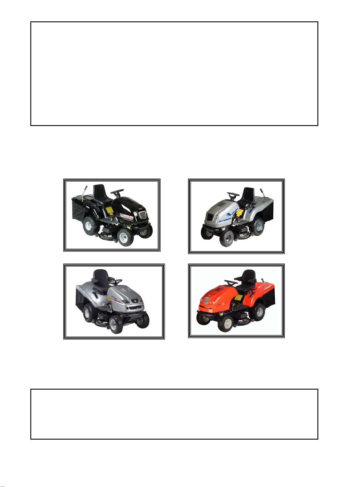
Lawn tractor
Rasentraktor
Tondeuse autoportée
April 2007
GB - Operator’s manual
D - Bedienungsanweisung
F - Manuel d’instruction

ENGLISH
1
CONTENTS ENGLISH
CONTENTS
EC DECLARATION OF CONFORMITY . . . . . . . . . . . . . . . . . . . . . .2
PREFACE . . . . . . . . . . . . . . . . . . . . . . . . . . . . . . . . . . . . . . . . . . . . .4
1.PROTECTION AND SAFE OF HEALTH AT WORK . . . . . . . . . . . . .5
1.1 SAFETY INSTRUCTIONS . . . . . . . . . . . . . . . . . . . . . . . . . . . . . . . .5
1.1.1 WORK ON A SLOPE . . . . . . . . . . . . . . . . . . . . . . . . . . . . . . . . . .6
1.1.2 DO NOT PERFORM . . . . . . . . . . . . . . . . . . . . . . . . . . . . . . . . . .6
1.1.3 SAFETY OF CHILDREN . . . . . . . . . . . . . . . . . . . . . . . . . . . . . .6
1.1.4 FIRE SAFETY . . . . . . . . . . . . . . . . . . . . . . . . . . . . . . . . . . . . . . .6
2. USE AND TECHNICAL DESCRIPTION . . . . . . . . . . . . . . . . . . .7
2.1 MACHINE USE . . . . . . . . . . . . . . . . . . . . . . . . . . . . . . . . . . . . . . . . .7
2.2 TECHNICAL DESCRIPTION . . . . . . . . . . . . . . . . . . . . . . . . . . . . .7
2.2.1 MACHINE FRAME . . . . . . . . . . . . . . . . . . . . . . . . . . . . . . . . . . .7
2.2.2 ENGINE INCLUDING ELECTRICAL INSTALLATION . . .7
2.2.3 GEARBOX INCLUDING DRIVE OF REAR WHEELS . . . . .7
2.2.4 FRONT AXLE WITH WHEELS INCLUDING STEERING .7
2.2.5 BY-PASS . . . . . . . . . . . . . . . . . . . . . . . . . . . . . . . . . . . . . . . . . . . .7
2.2.6 BONNET AND PLACE OF OPERATOR . . . . . . . . . . . . . . . . .7
2.2.7 MOWING MECHANISM . . . . . . . . . . . . . . . . . . . . . . . . . . . . . .7
2.2.8 GRASS COLLECTING BIN . . . . . . . . . . . . . . . . . . . . . . . . . . .7
2.3 MACHINE EQUIPMENT . . . . . . . . . . . . . . . . . . . . . . . . . . . . . . . . .7
2.4 MARKING . . . . . . . . . . . . . . . . . . . . . . . . . . . . . . . . . . . . . . . . . . . . .8
3. TECHNICAL PARAMETERS . . . . . . . . . . . . . . . . . . . . . . . . . . . .9
4. UNPACKING . . . . . . . . . . . . . . . . . . . . . . . . . . . . . . . . . . . . . . .12
4.1 CHECK AFTER UNPACKING . . . . . . . . . . . . . . . . . . . . . . . . . . .12
4.1.1 DISPOSE OF PACKAGE . . . . . . . . . . . . . . . . . . . . . . . . . . . . . .12
4.2 PREPARATION FOR PUTTING INTO OPERATION . . . . . . . .12
4.2.1 ASSEMBLY OF STEERING WHEEL . . . . . . . . . . . . . . . . . . .12
4.2.2 ASSEMBLY OF SEAT . . . . . . . . . . . . . . . . . . . . . . . . . . . . . . . .12
4.2.3 SEAT POSITION ADJUSTMENT . . . . . . . . . . . . . . . . . . . . . .12
4.2.4 CONNECTION OF ACCUMULATOR . . . . . . . . . . . . . . . . . .12
4.2.5 ASSEMBLY OF SUSPENSION . . . . . . . . . . . . . . . . . . . . . . . .13
4.2.6 ASSEMBLY OF GRASS COLLECTING BIN . . . . . . . . . . . .13
4.2.7 SUSPENSION OF GRASS COLLECTING BIN . . . . . . . . . .13
5. PUTTING INTO OPERATION . . . . . . . . . . . . . . . . . . . . . . . . . .14
5.1 CHECK OF OIL LEVEL IN ENGINE . . . . . . . . . . . . . . . . . . . . .14
5.2 CHECK OF ACCUMULATOR . . . . . . . . . . . . . . . . . . . . . . . . . . .14
5.3 FILLING THE TANK WITH PETROL . . . . . . . . . . . . . . . . . . . .14
6 . MACHINE CONTROL . . . . . . . . . . . . . . . . . . . . . . . . . . . . . . . .15
6.1 DESCRIPTION AND FUNCTION OF CONTROLS . . . . . . . . .15
6.1.1 SWITCH OF MOWING MECHANISM . . . . . . . . . . . . . . . . .15
6.1.2 SWITCH BOX . . . . . . . . . . . . . . . . . . . . . . . . . . . . . . . . . . . . . . .15
6.1.3 GAS CONTROL LEVER . . . . . . . . . . . . . . . . . . . . . . . . . . . . . .15
6.1.4 CHOKE . . . . . . . . . . . . . . . . . . . . . . . . . . . . . . . . . . . . . . . . . . . .15
6.1.5 BUZZER . . . . . . . . . . . . . . . . . . . . . . . . . . . . . . . . . . . . . . . . . . .15
6.1.6 HEADLAMP SWITCH . . . . . . . . . . . . . . . . . . . . . . . . . . . . . . .15
6.1.7 ENGINE HOUR METER . . . . . . . . . . . . . . . . . . . . . . . . . . . . .15
6.1.8 CRUISE CONTROL DEVICE . . . . . . . . . . . . . . . . . . . . . . . . .16
6.1.9 AUT/MAN SWITCH . . . . . . . . . . . . . . . . . . . . . . . . . . . . . . . . .16
6.1.10 RESET SWITCH . . . . . . . . . . . . . . . . . . . . . . . . . . . . . . . . . . . .16
6.1.11 SWITCH OF GRASS COLLECTING BIN DUMPING . . . .16
6.1.12 BRAKE . . . . . . . . . . . . . . . . . . . . . . . . . . . . . . . . . . . . . . . . . . .16
6.1.13 PARKING BRAKE LEVER . . . . . . . . . . . . . . . . . . . . . . . . . . .16
6.1.14 TRAVEL PEDAL . . . . . . . . . . . . . . . . . . . . . . . . . . . . . . . . . . .16
6.1.15 BY-PASS LEVER . . . . . . . . . . . . . . . . . . . . . . . . . . . . . . . . . . . .17
6.1.16 DIFFERENTIAL LOCK PEDAL . . . . . . . . . . . . . . . . . . . . . .17
6.1.17 MOWING MECHANISM HEIGHT SETTING-UP LEVER 17
6.1.18 MULCHING FLAP LEVER . . . . . . . . . . . . . . . . . . . . . . . . . .17
6.1.19 CLOSURE OF FUEL SUPPLY . . . . . . . . . . . . . . . . . . . . . . . .17
6.2 OPERATION AND ATTENDANCE . . . . . . . . . . . . . . . . . . . . . . .18
6.2.1 SUSPENSION OF GRASS COLLECTING BIN . . . . . . . . . .18
6.2.2 ENGINE STARTING . . . . . . . . . . . . . . . . . . . . . . . . . . . . . . . .18
6.2.3 ENGINE STOPPING . . . . . . . . . . . . . . . . . . . . . . . . . . . . . . . .18
6.2.4 MOWING MECHANISM TURNING ON AND OFF . . . . .18
6.2.5 MOWING MECHANISM HEIGHT SETTING UP . . . . . . . .19
6.3 TRAVEL . . . . . . . . . . . . . . . . . . . . . . . . . . . . . . . . . . . . . . . . . . . . . .19
6.4 TRAVEL SPEED AND MOWING OF GRASS . . . . . . . . . . . . . .19
6.5 TRAVEL ON A SLOPE . . . . . . . . . . . . . . . . . . . . . . . . . . . . . . . . . .19
6.6 DISCHARGING OF GRASS COLLECTING BIN . . . . . . . . . . .19
7. MACHINE MAINTENANCE . . . . . . . . . . . . . . . . . . . . . . . . . . .20
7.1 SUMMARY OF CHECKS AND MAINTENANCE . . . . . . . . . .20
7.2 TYRE PRESSURE CHECK . . . . . . . . . . . . . . . . . . . . . . . . . . . . . .20
7.3 MAINTENANCE AFTER WORK . . . . . . . . . . . . . . . . . . . . . . . . .20
7.3.1 CLEANING . . . . . . . . . . . . . . . . . . . . . . . . . . . . . . . . . . . . . . . .20
7.3.2 WASHING . . . . . . . . . . . . . . . . . . . . . . . . . . . . . . . . . . . . . . . . .21
7.4 ACCUMULATOR MAINTENANCE . . . . . . . . . . . . . . . . . . . . . .21
7.5 ENGINE MAINTENANCE . . . . . . . . . . . . . . . . . . . . . . . . . . . . . .21
7.5.1 CHECK OF OIL LEVEL IN ENGINE . . . . . . . . . . . . . . . . . .21
7.5.2 OIL CHANGING . . . . . . . . . . . . . . . . . . . . . . . . . . . . . . . . . . . .21
7.5.3 FUEL FILTER REPLACEMENT . . . . . . . . . . . . . . . . . . . . . . .21
7.5.4 AIR FILTER MAINTENANCE . . . . . . . . . . . . . . . . . . . . . . . .21
7.5.5 SPARKING PLUG MAINTENANCE . . . . . . . . . . . . . . . . . . .21
7.6 LUBRICATION . . . . . . . . . . . . . . . . . . . . . . . . . . . . . . . . . . . . . . . .21
7.7 REPLACEMENT OF BULB . . . . . . . . . . . . . . . . . . . . . . . . . . . . . .22
7.8 FUSE REPLACEMENT . . . . . . . . . . . . . . . . . . . . . . . . . . . . . . . . .22
7.9 MACHINE JACKING UP . . . . . . . . . . . . . . . . . . . . . . . . . . . . . . . .22
7.10 REPLACEMENT OF MOWING MECHANISM KNIVES . . . .22
7.10.1 SHARPENING OF KNIVES . . . . . . . . . . . . . . . . . . . . . . . . . .23
7.11 STEERING UNIT MAINTENANCE . . . . . . . . . . . . . . . . . . . . . .23
7.12 CHECK AND ADJUSTMENT OF TRAVEL DRIVE BELT . . .23
7.13 CHECK AND ADJUSTMENT OF MOWING MECHANISM
SETTING-UP . . . . . . . . . . . . . . . . . . . . . . . . . . . . . . . . . . . . . . . . .23
7.14 CHECK AND ADJUSTMENT OF MOWING
MECHANISM DRIVE V-BELT . . . . . . . . . . . . . . . . . . . . . . . . . .23
7.15 MOWING MECHANISM WITHDRAWAL
FROM MACHINE . . . . . . . . . . . . . . . . . . . . . . . . . . . . . . . . . . . . .24
7.16 ADJUSTMENT OF KNIVES DRIVE INDENTED BELT . . . .24
7.17 REPLACEMENT OF BELTS . . . . . . . . . . . . . . . . . . . . . . . . . . . .24
7.18 WHEEL CHANGING . . . . . . . . . . . . . . . . . . . . . . . . . . . . . . . . . .24
7.19 HYDROSTATIC GEARBOX MAINTENANCE . . . . . . . . . . . . .24
7.20 BRAKE ADJUSTMENT . . . . . . . . . . . . . . . . . . . . . . . . . . . . . . . .25
7.21 OVERVIEW OF TIGHTENING TORQUES OF SCREW
CONNECTIONS . . . . . . . . . . . . . . . . . . . . . . . . . . . . . . . . . . . . . .25
8. REMOVAL OF FAILURES AND DEFECTS . . . . . . . . . . . . . . . .26
8.1 SPARE PARTS ORDERING . . . . . . . . . . . . . . . . . . . . . . . . . . . . . .28
8.2 GUARANTEE . . . . . . . . . . . . . . . . . . . . . . . . . . . . . . . . . . . . . . . . .28
9. AFTER-SEASON MAINTENANCE, MACHINE STORAGE . . . . .28
10. MACHINE DISPOSAL . . . . . . . . . . . . . . . . . . . . . . . . . . . . . . .28

INTRODUCTION ENGLISH
2
EC DECLARATION OF CONFORMITY
acc.: Council Directive no. 98/37/EC (NV 24/2003 Sb. Decree of the Government)
Council Directive no. 89/336/EEC (NV 18/2003 Sb. Decree of the Government)
Directive 2000/14/EC (NV 9/2002 Sb. Decree of the Government)
A. We: Seco GROUP a.s., Pobřežní 44/362, Praha 8
odštěpný závod 02 AGS Jičín, Jungmannova 11
IČO: 60193450
are issuing, on our own responsibility, this declaration:
B. Machine
- name: Self-propelled mowing machine
- type: AJ 102
Description: The AJ 102 is a four-wheel self-propelled mowing machine with Briggs & Stratton 15,5HP, 16HP, 18HP, 20HP or TECUMSEH 17HP, 18HP,
20HP, 22HP engine. The drive from the engine is transmitted by V-belts via an electromagnetic clutch to the mowing mechanism and transmission
gearbox. The mowing mechanism is of a two-knife type driven by a double-sided indented belt. The mowed grass is taken away into the collecting
bin or directed by means of a deflector to the ground. Instead of the grass collecting a mulching can be carried out by means of two auxiliary
knives when the discharge tunnel is blinded.
C. Regulations the conformity was judged with:
ČSN EN ISO 12100-2, EN 836+A2, EN 1050, EN ISO 3767-1,2,3, EN 294, EN 15323, ISO 6682, CISPR 12, EN ISO 11201
D. Judgment of conformity was carried out by means of the procedure set down in:
- Council Directive No. 98/37/EC, Article 8, par. 2 a), (eqv. §3, par. 1 a), NV no. 24/2003 Sb.)
- Council Directive No. 89/336/EEC, Article 10, par.c 1, (eqv. §4, par. 1, NV no. 18/2003 Sb.)
- Directive 2000/14/EC, Appendix VIII (eqv. appendix 7, NV č. 9/2002 Sb.)
E. We confirm that:
- machine defined by the data stated is in conformity with the requirements specified in technical regulations stated above, and is the s a f e
machine under conditions of usual use
- provisions have been accepted for the security of conformity of all products being put on the market with the technical documentation and
requirements of technical regulations
- guaranteed acoustic power level is 100 dB(A).
Measured average values of acoustic power level according to the engine used:
Technical documentation in the extent acc. to the appendix V to the directives 98/37/EC and 2000/14/EC is filed at the manufacturer at the place of business:
Seco GROUP
odštěpný závod 02 AGS
Jungmannova 11
506 48 Jičín
Ing. Petr Fischer
vice-chairman of board of directors
In Jičín, October 1, 2005
Engine Speed (rpm) Acoustic power measured value [dB(A)]
Briggs & Stratton 15,5 HP I/C 2700 w100 97,36
Briggs & Stratton 16 HP VANGUARD 2800 w100 97,49
Briggs & Stratton 18 HP VANGUARD 2800 w100 97,01
Briggs & Stratton 17,5 HP Intek 2700 w100
Briggs & Stratton 18 HP Intek 2800 w100 97,49
Briggs & Stratton 20 HP Intek 2800 w100 97,29
Briggs & Stratton 22 HP Intek 2800 w100
HONDA K1 20 HP 2800 w100 97,58
HONDA 16 HP 2700 w100 98,28
TECUMSEH ENDURO VT 17 HP 2700 w100 99,32
TECUMSEH ENDURO VT 18 HP 2400 w100 97,90
TECUMSEH ENDURO VT 20 HP 2400 w100 98,00
TECUMSEH ENDURO VT 22 HP 2500 w100 99,14
TECUMSEH ENDURO VT 25 HP 2500 w100

INTRODUCTION ENGLISH
3
EC DECLARATION OF CONFORMITY
acc.: Council Directive no. 98/37/EC (NV 24/2003 Sb. Decree of the Government)
Council Directive no. 89/336/EEC (NV 18/2003 Sb. Decree of the Government)
Directive 2000/14/EC (NV 9/2002 Sb. Decree of the Government)
A. We: Seco GROUP a.s., Pobřežní 44/362, Praha 8
odštěpný závod 02 AGS Jičín, Jungmannova 11
IČO: 60193450
are issuing, on our own responsibility, this declaration:
B. Machine
- name: Self-propelled mowing machine
- type: AG 122
Description: The AJ 102 is a four-wheel self-propelled mowing machine with Briggs & Stratton 18 HP, 20 HP or HONDA 20 HP engine. The drive from
the engine is transmitted by V-belts via an electromagnetic clutch to the mowing mechanism and transmission gearbox. The mowing mechanism
is of a two-knife type driven by a double-sided indented belt. The mowed grass is taken away into the collecting bin or directed by means of
a deflector to the ground. Instead of the grass collecting a mulching can be carried out by means of two auxiliary knives when the discharge
tunnel is blinded.
C. Regulations the conformity was judged with:
ČSN EN ISO 12 100-2, EN 836+A2, CISPR 12, EN ISO 11201
D. Judgment of conformity was carried out by means of the procedure set down in:
- Council Directive No. 98/37/EC, Article 8, par. 2 a), (eqv. §3, par. 1 a), NV no. 24/2003 Sb.)
- Council Directive No. 89/336/EEC, Article 10, par.c 1, (eqv. §4, par. 1, NV no. 18/2003 Sb.)
- Directive 2000/14/EC, Appendix VIII (eqv. appendix 7, NV č. 9/2002 Sb.)
E. We confirm that:
- machine defined by the data stated is in conformity with the requirements specified in technical regulations stated above, and is the s a f e
machine under conditions of usual use
- provisions have been accepted for the security of conformity of all products being put on the market with the technical documentation and
requirements of technical regulations
- guaranteed acoustic power level is 105 dB(A)
Measured average values of acoustic power level according to the engine used:
Technical documentation in the extent acc. to the appendix V to the directives 98/37/EC and 2000/14/EC is filed at the manufacturer at the place of business:
Seco GROUP
odštěpný závod 02 AGS
Jungmannova 11
506 48 Jičín
Ing. Petr Fischer
vice-chairman of board of directors
In Jičín, October 1, 2005
Engine Speed (rpm) Acoustic power measured value [dB(A)]
Briggs & Stratton 18 HP VANGUARD 3000 w100 102,15
Briggs & Stratton 20 HP VANGUARD 3000 w100
Briggs & Stratton 20 HP Intek 3000 w100 101,87
Briggs & Stratton 22 HP Intek 3000 w100
HONDA K1 20 HP 3000 w100 102,57

ENGLISH
4
INTRODUCTION ENGLISH
PREFACE
Dear customer,
we thank You very much for Your decision and choice to buy our mowing machine. The Seco GROUP a.s., being a succession owner of the Knotek a spol.,
Agrostroj and AGS Jičín companies, is well-known in the European as well as in the world markets as the manufacturer of the AGS brand quality machines
for maintenance of grass areas.
Our object was to design and manufacture a high-quality powerful lawn-mowing machine. We are sure You will agree, provided You have had an opportunity
to try the quality of our machine operation, that we succeeded and fulfilled our task.
It now depends only on You what way of working with this machine You will choose to serve You to Your satisfaction as long as possible.
Study this manual carefully. Follow the instructions stated in it meticulously in order to make the use of the machine bought easy and to ensure its optimum
utilization and long service life.
Use this self-propelled mowing machine only for the purpose it was manufactured for. Any use not specified in this manual may be dangerous and may be
a cause of the machine damage. This can result in the invalidation of the guarantee as, in such a case, the manufacturer disclaims any responsibility.
Service staff trained and tested in the manufacturing plant is available in more than 100 of our authorized services throughout the Europe.

ENGLISH
5
PROTECTION AND SAFETY ENGLISH
1. PROTECTION AND SAFETY OF HEALTH AT WORK
The AJ 102 and AG 122 types of self-propelled mowing machines with the commercial name STARJET are manufactured in accordance with the effective
European safety standards.
1.1 SAFETY INSTRUCTIONS
Before the first use of Your mowing machine study particularly this Operator's manual. When operating the mowing machine follow meticulously the safety
instructions stated in this manual. In case the machine was used at variance with the instructions and information specified in this manual or with legal
regulations, the manufacturer bears no liability for the contingent damages and the user loses his right to the guarantee repair.
Do not use the machine if any of its protective devices is damaged or missing.
All the covers and other protective devices must always be on their places.
So, do not remove or do not put out of operation any machine protective device.
Check regularly the functions of these devices.
It is not allowed to carry out any technical modification on the machine without manufacturer's approval in writing.
Inadmissible changes can conduce to the hazardous conditions of the safety of work and so to the cancellation of the guarantee.
Do not change the adjustment of the engine speed governor or engine speed limit device.
Do not remove safety stickers or labels from the machine.
Before putting the machine into operation make Yourself thoroughly familiar with all its control elements and master the manipulation
with them in such a way that You will be able to stop the machine or to turn off the engine immediately.
Always keep the machine and its equipment in cleanness and in good technical condition.
Machine can only be driven by a person who is above 18 years of age and is acquainted with the instructions included in this manual.
Machine must not be used for a work on slopes having bigger gradient than 10° (17%).
Machine user is responsible for the safety of persons being in the machine working area.
Do not move in the machine vicinity or under it if it is lifted and it is not properly secured against falling down or turning over.
Machine user is responsible for the safety of persons being in the machine working area.
Do not move in the machine vicinity or under it if it is lifted and it is not properly secured against falling down or turning over.
Transport of other persons, animals or burdens directly on the machine is prohibited.
The transport of burdens is only allowed on a trailer whose type was approved by the machine manufacturer.
If You are leaving the machine even for a short time always withdraw the key from the ignition.
If You operate the machine outside the working area where the mowing is performed turn always the mowing mechanism off
and raise it to the transport position.
If the mowing is turned off the mowing mechanism must always be in the transport position.
Always turn off the mowing mechanism as well as the engine and withdraw the key from the ignition if:
• You are cleaning the machine
• You are removing the clogging of the mowing mechanism with grass
•You have run on a foreign object and it is necessary to find out if the machine is not damaged, contingently to remove the damage
• machine is unnaturally vigorously vibrating and it is necessary to find out the cause of vibrations
•You are repairing the engine or other movable parts (disconnect also the cables from the sparking plugs)
Before You start the work with the machine, remove all stones, pieces of wood, wires, bones, fallen branches and other foreign objects from the area on
which the mowing will be carried out as they could be flung away during the mowing. During the work avoid the molehills, concrete posts, stumps, patch
and pavement kerbs as these must not come into contact with knives in order to prevent from a damage to the mowing mechanisms or the machine mecha-
nism. In case of striking against a solid object, stop, turn off the mowing mechanism as well as the engine and check the whole machine, especially the steering
mechanism. If need be, carry out the repair before restarting the machine. Remove all defects before further use. Check thoroughly, before starting the work,
especially the tension of belts, sharpness of knives and cleanness inside the pressed piece of mowing mechanism. Rotary knives are sharp and can cause an
injury. At any manipulation with them use protective gloves or wrap them. Check regularly the bolts and nuts fixing the knives and see to it that they are
tightened with the correct tightening torque (see the chapter 7.21). Pay increased attention to the self-locking nuts. The self-locking ability of the nut is
reduced after its second loosening, therefore the nut has to be replaced with a new one. The components of the grass collector are subject to stresses, they
can be damaged, their functions worsened and it can happen that objects may fall out from the bin. Check the components regularly and if needed replace
those components which are to be replaced according to the recommendation of the machine manufacturer.
Where it is possible, avoid the work with the machine in the wet grass.
Avoid the obstacles (e.g. a sudden change of the slope gradient, ditches etc.) where the machine could turn over.
Operate the machine during the day light or at a good artificial lighting only.
It is forbidden to run the machine on the public roads.
Do not wear loose clothing and shorts at the machine operation. Use the solid closed shoes.
Do not operate the machine after consuming alcohol, drugs or medicaments affecting the receptiveness.
Do not operate the machine if You suffer from dizziness, faintness or You are otherwise weakened or unconcentrated.
Do not let the engine run in closed spaces. Exhaust fumes contain the substances which though odourless are deadly poisonous.
Do not start the engine without the exhaust.
Observe all requirements concerning the fire safety stated in the chapter 1.1.4.
Noise generated during the mowing does not normally exceed the highest values of acoustic pressure and acoustic power which are stated in the chapter 3.
"Technical parameters" of this manual. However, the level of noise can be increased, in some cases, for a short time at certain conditions and due to the
property of ground. The machine manufacturer recommends wearing of hearing protection as the exposure to an extremely loud noise or long lasting noise
may cause permanent hearing damage.
Warning !
This self-propelled mowing machine can cut hands, legs or shoot out the objects in case of not observing the safety of work.
Do not place the hands or legs under the cover of the mowing device. Always keep parts of your body away from the rotating or moving parts of the mower.

ENGLISH
6
GRAPHICAL REPRESENTATION OF WARNINGS AND ADVICES ENGLISH
Danger Keep hands out
when it is running
At a repair proceed
acc. to the manual
Never leave mower
when it is running
Flying-off objects
Read the Operator's
manual
Do not mow in
vicinity of persons
Never carry another
persons
Never drive across
a slope
Keep unauthorized
persons in a safe
distance
Rotating knives Do not step on Do not touch – Risk of burn Max. working gradient 10°
10°
Above illustrated labels and stickers are fastened on the machine.
1.1.1 WORK ON A SLOPE
Slopes are the main cause of accidents, loss of control over the machine or subsequent turning over of the machine that can result in a serious injury or dead.
The mowing on a slope always requires increased attention. If You are not sure, or it is above Your capabilities, do not mow on a slope. The self-propelled
mowing machine may be used on slopes with the maximum gradient up to 10°(17%) and only in the direction of the thalweg, i.e. up and down. The ride along the
contour line is not permitted. The change of direction requires increased caution. Do not turn on a slope unless it is necessary. Beware of holes, roots and uneven-
ness of the ground. Uneven ground may cause the overturn of the machine. The high grass may cover hidden obstacles. Remove beforehand, from this reason,
all the obstructing objects (see the previous chapter 1.1) from the area where the mowing will be carried out. Choose such a speed You will not have to stop on
the slope. Perform all moves on the slope slowly and smoothly. Do not perform any sudden changes of the speed or direction. Avoid starting or stopping on
a slope. In case the wheels are loosing the adhesion, stop the drive of knives and ride slowly downwards. When on a slope, be careful and set the mower in motion
slowly to prevent from making a "jump". Always reduce the machine travel speed when approaching a slope, especially when riding downwards, reduce the travel
speed to the minimum in order to utilize the brake effect of the gearbox.
1.1.2 DO NOT PERFORM
Do not mow near a dump, hollow or banks. The mower may overturn suddenly if a wheel gets over the margin of the hollow, ditch or edge which can tear off.
Do not mow wet grass as the reduced adhesion may by a cause of a skidding.
Do not try to keep stability by stepping on the ground.
1.1.3 SAFETY OF CHILDREN
A tragic accident can happen if the mowing machine operator is not prepared for the presence of children.
The movement of the mowing machine attracts their attention. Never relay on that the children stay in the place where You saw them to stand for the last
time.
Do not leave the children without the supervision in the place where You are mowing the grass.
Be alert and turn off the machine in case the children are approaching it.
Before and during reversing look behind Yourself and onto the ground.
Never transport children as they can fall down and get seriously injured, or they could hazardously interfere in the machine control. Never permit children
to operate the machine.
Pay extra attention in places with limited visibility (in the vicinity of trees, bushes, masonry, etc.).
1.1.4 FIRE SAFETY
With the use of the mowing machine it is necessary to follow the rules and regulations for the safety of work and fire safety related to the work with this sort of
machines. Remove regularly the inflammable substances (dry grass, leaves, and likewise) from the area of the exhaust, engine, accumulator and from all
places where they could come into contact with petrol or oil, consequently to inflame and set the machine on fire.
Let the engine of the mowing machine cool down before You store it in a closed space.
Pay extra attention when working with petrol, oil and other combustibles. They are highly inflammable matters whose vapours are explosive. Do not smoke
during this work. Never unscrew the cap of the tank and refill the petrol when the engine is running, or if the engine is hot or if the machine is in a closed
space. Check the supply of the petrol before use, do not fill the petrol up to the tank neck. The temperature of the engine and sun as well as the fuel expan-
sivity may result in an overflow and ensuing fire.
To store the combustibles, use only the vessels specified for this purpose. Never store any canister with petrol or the machine inside the building in the vicinity
of any source of heat.
Pay extra attention when handling the accumulator. The gas in the accumulator is highly explosive, therefore do not smoke or use an open fire in the accu-
mulator vicinity in order to prevent from serious injuries.

ENGLISH
7
USE AND TECHNICAL DESCRIPTION ENGLISH
2. USE AND TECHNICAL DESCRIPTION
2.1 MACHINE USE
The machine of the AJ 102 or AG 122 type with the commercial name STARJET is a two-axle self-propelled mowing machine intended for the mowing of
flat maintained grass areas with the maximum height of vegetation of 10 cm, e.g. in parks, gardens and playgrounds, contingently on gentle slopes on which
there are no foreign objects (fallen branches, stones, solid objects, etc.). The gradient of slope must not exceed 10°(17%).
Always slow down when driving on an uneven ground, and use the ramps when crossing a local unevenness higher than 8 cm (kerbs). Without use of the ramps
there is a danger of a serious damage to the machine.
Only the accessories whose usage is approved by the machine manufacturer may be connected to the mower.
The use of other accessory means the immediate loss of the guarantee.
2.2 TECHNICAL DESCRIPTION
The mowing machine of the AJ102 or AG122 type consists of the following basic groups:
2.2.1 MACHINE FRAME
The machine frame is welded from steel tubes and metal sheets of 3 mm thickness. It is a supporting element of the engine, gearbox, front and rear axles,
steering, drives, mowing mechanism, accumulator, fuel tank and other needed equipment of the machine.
2.2.2 ENGINE INCLUDING ELECTRICAL INSTALLATION
The engines used in mowing machines are four-stroke petrol engines with vertical output shaft. The engine is fastened firmly to the frame in the machine
front part. The drive from the engine is transmitted to the gearbox by a V-belt. The accumulator is positioned either in a box under the seat or under the
front bonnet in dependence on the machine version.
2.2.3 GEARBOX INCLUDING DRIVE OF REAR WHEELS
The gearbox is of a type with a hydrostatic transmission of power. The gear change is carried out by depressing the travel pedal smoothly forwards or back-
wards.
2.2.4 FRONT AXLE WITH WHEELS INCLUDING STEERING UNIT
The front axle is of a massive cast-iron construction. It is suspended on a hollow pivot enabling the swing of the wheels. The steering is performed by means
of a steering wheel pinion meshing into a gear segment.
2.2.5 BY-PASS
The by-pass lever serves for the disengaging and engaging of the drive from the gearbox to the rear wheels. It is located close by the rear left wheel.
The position of its location in front of the wheel or behind the wheel is dependent on the machine version.
2.2.6 BONNET AND PLACE OF OPERATOR
The bonnet is made of plastics. The metal parts coherent with bonnet are protected with powder painting. The place of the operator is solved ergonomical-
ly so that all control elements are easily accessible and lightly controllable. The seat used ensures the comfortable operating.
2.2.7 MOWING MECHANISM
The mowing mechanism consists of a cover, main plate, pulleys, shaft with bearings and two mowing knives. The drive of the mowing mechanism is carried
out by a V-belt from the engine via an electromagnetic clutch which is fixed on the output shaft of the engine. The cover made of a thick steel sheet is used
at the machines having the width of mowing of 102 cm, the machines having the width of mowing of 122 cm are equipped with the cover made as an alu-
minium casting.
2.2.8 GRASS COLLECTING BIN
The grass collecting bin is constructed of a frame, lid and textile bag. The frame is made of steel tubes.
2.3 MACHINE EQUIPMENT
Hydrostatic gearbox TUFF-TORQ K46
Hydrostatic gearbox TUFF-TORQ K62
BUZZER
ENGINE HOUR METER
LOCK OF DIFFERENTIAL
MULCHING FLAP
CRUISE CONTROL
AUT/MAN SWITCH
TRIPLEX KNIFE

ENGLISH
2.4 MARKING
Each self-propelled mowing machine is marked with an identification plate located under the seat.
It includes the following data:
1. Type of machine
2. Serial number
3. Year of production
4. Name and address of manufacturer
5. Engine power output
6. Engine speed in rpm
7. Weight
8. EC regulations the conformity of product was judged with
9 Mark of product conformity
10. Guaranteed noise level acc. to the 2000/14/EC directive
The serial number will be recorded on the second page of this manual cover
by the dealer during the machine handing over.
8
USE AND TECHNICAL DESCRIPTION ENGLISH

ENGLISH
9
TECHNICAL PARAMETERS ENGLISH
3. TECHNICAL PARAMETERS
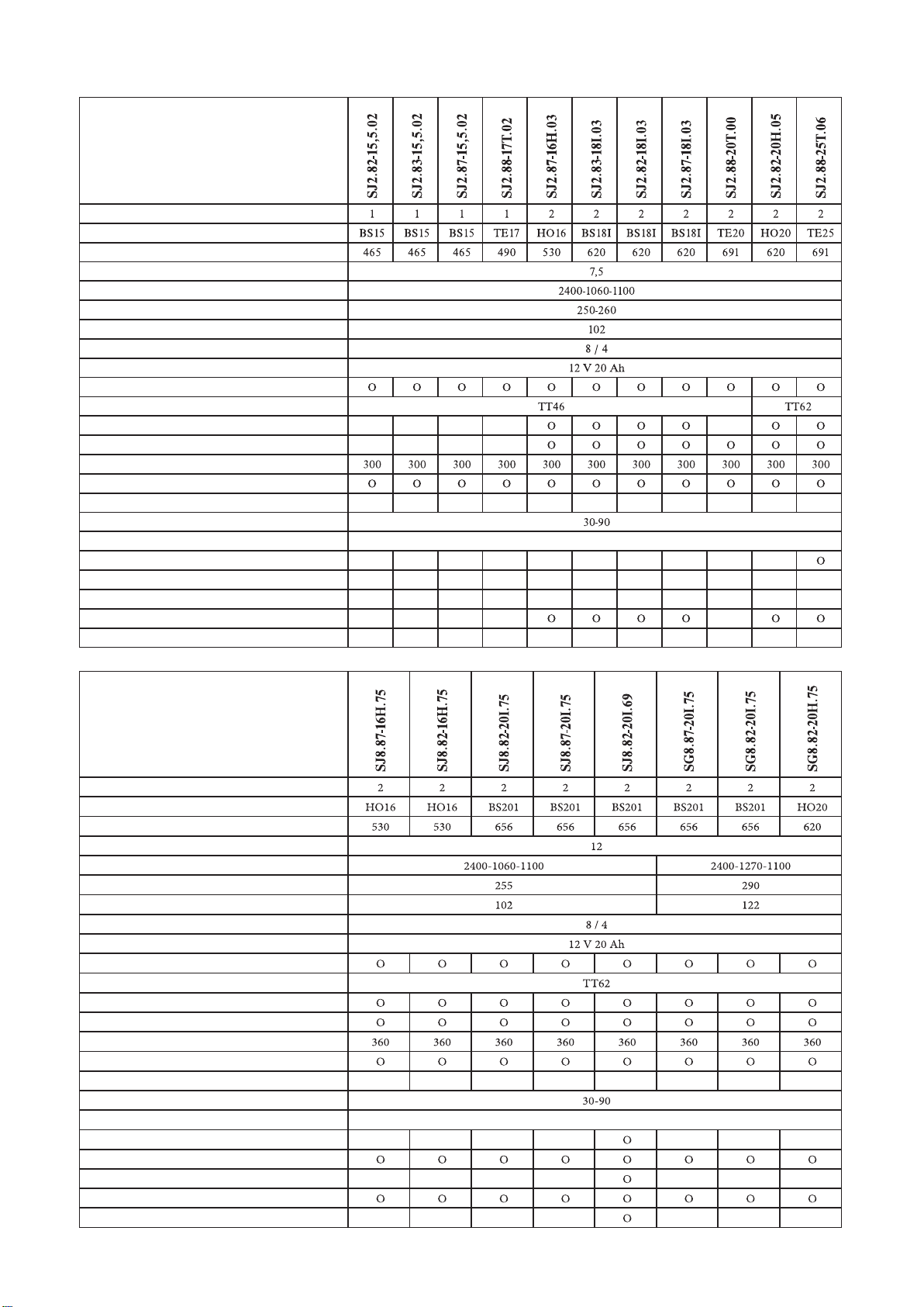
AJ102 type
*declared value of total vibrations
AG122 type
The particular data for Your mowing machine can be found in the following tables according to the model number which is written down in the inner side
of this manual cover.
Explanatory notes:
Engines: Gearboxes:
BS15 Briggs&Stratton 15,5HP I/C AVS TT46 TUFF-TORQ K46
BS16 Briggs&Stratton 16HP VANGUARD V-TWIN TT62 TUFF-TORQ K62
BS18Briggs&Stratton 18HP VANGUARD V-TWIN
BS20 Briggs&Stratton 20HP VANGUARD V-TWIN
BS18I Briggs&Stratton 18HP INTEK
BS20I Briggs&Stratton 20HP INTEK
HO16 Honda 16HP GCV530
HO20 Honda 20HP GXV620
TE17 Tecumseh 17HP ENDURO
TE20 Tecumseh 20HP ENDURO TV
Engine
seat
steering wheel
floor
Declared emission level
of accoustic power
in operator's place
LpAd (dB) EN ISO 11201
Guaranteed level
of accoustic power
LWA(dB)
Weighted effective value
of vibration acceleration (min.s-2)
Revs w100 rpm
Engine
seat
steering wheel
floor
Declared emission level
of accoustic power
in operator's place
LpAd (dB) EN ISO 11201
Guaranteed level
of accoustic power
LWA (dB)
Weighted effective value
of vibration acceleration (min.s-2)
Revs w100 rpm
10
TECHNICAL PARAMETERS ENGLISH
ModelModel
electromagnetic
electromagnetic
Number of cylinders
Engine
Volume (c.c.)
Tank capacity ( l )
Dimensions: length-width-height (mm)
Weight (kg)
Width of mowing (cm)
Max. forward speed / reverse (km/hour)
Accumulator
Front wheels 16x6.50-8 / rear 20x10-8
Gearbox
Cruise control
Engine hour meter
Grass collecting bin (l)
Full bin - warning BUZZER
Full bin - warning AUT/MAN switch
Height of mowing (mm)
Mowing mechanism clutch
Differential lock
TRIPLEX knife
Grass collecting bin electrical dumping
De Luxe seat
Mulching flap

TECHNICAL PARAMETERS ENGLISH
11
Model Model
electromagnetic
electromagnetic
Number of cylinders
Engine
Volume (c.c.)
Tank capacity ( l )
Dimensions: length-width-height (mm)
Weight (kg)
Width of mowing (cm)
Max. forward speed / reverse (km/hour)
Accumulator
Front wheels 16x6.50-8 / rear 20x10-8
Gearbox
Cruise control
Engine hour meter
Grass collecting bin (l)
Full bin - warning BUZZER
Full bin - warning AUT/MAN switch
Height of mowing (mm)
Mowing mechanism clutch
Differential lock
TRIPLEX knife
Grass collecting bin electrical dumping
De Luxe seat
Mulching flap

UNPACKING ENGLISH
4 . UNPACKING
The self-propelled mowing machine is delivered in crates reinforced with cratewood. Some machine groups have been dismantled in the manufacturing plant
due to the transport reasons. They will be reassembled before the machine putting into operation. The machine unpacking and preparation for the opera-
tion is carried out by the vendor within the framework of service before sale.
4.1 CHECK AFTER UNPACKING
After removing the wrapping take down carefully the machine from the pallet - use the ramps otherwise there is a risk of the machine damage. Check if the
machine was not damaged during the transport. Unpack also all dismantled groups and check them.
In the basic packing are delivered:
• mowing machine
• steering wheel
• seat
• grass collecting bin (it is partially dismantled and is in the cardboard box together with the suspension, connecting parts and two triangular self-adhesive
labels of yellow colour)
• documentation (packing list, mowing machine operator's manual, engine operating instructions, accumulator operating instructions, Service book)
4.1.1 DISPOSE OF PACKAGE
After the machine unpacking it is necessary to dispose of the wrapping. When disposing, observe the appurtenant law on waste materials valid in the coun-
try of the machine user. Separate the packing material according to the appropriate packaging catalogue. This procedure can be entrusted to a specialized
firm.
4.2 PREPARATION FOR PUTTING INTO OPERATION
With respect to the technical character of this work, the mowing machine preparation
into operation is carried out by Your vendor (in accordance with the instructions
of the machine manufacturer).
4.2.1 ASSEMBLY OF STEERING WHEEL
Place the machine on an even surface and align the front wheels into straight direction.
Mount the steering wheel and secure it by the pin supplied.
4.2.2 ASSEMBLY OF SEAT
Remove the seat wrapping cover.
Put the seat on its place in the machine and fasten it by means
of screws being preassembled in the seat.
4.2.3 SEAT POSITION ADJUSTMENT
Adjust the position of the seat in the following way:
Loosen the screws with plastic roses.
Shift the seat forward or backward to the desired position.
Retighten the screws with plastic roses.
4.2.4 CONNECTION OF ACCUMULATOR
When putting the accumulator into operation, proceed according to the instructions stated in the Accumulator operating instructions.
The accumulator is placed in a box under the seat (at the SJ2... and SJ4... machine type) or under the front bonnet (at the SJ8... a SG8... machine type).
Loosen the screws on the accumulator pole outlets.
Connect the red wire to the (+) pole of the accumulator and retighten the screw.
Connect the brown wire to the (–) pole of the accumulator and retighten the screw.
12
WARNING:
Reverse connection of the wires then stated above will result in a damage to the machine.
When disconnecting the accumulator, always disconnect the (–) pole as the first.
Follow the instruction for the maintenance stated in the accumulator operating instructions.
UNPACKING ENGLISH
4.2.5 ASSEMBLY OF SUSPENSION
Unscrew the two central screws on the rear plate of the mowing machine.
Place the suspension so that holes for its fastening will coincide with threaded holes.
Fasten the suspension by means of the screws unscrewed before.
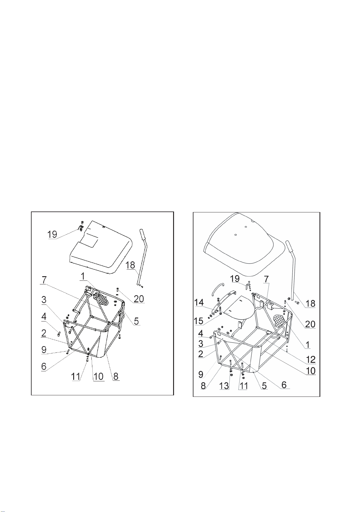
4.2.6 ASSEMBLY OF GRASS COLLECTING BIN
The grass collecting bin is preassembled, it is necessary to mount it onto the machine and adjust it.
Take out the grass bin from the crate, open the bag 1, tilt down the front tube 2, insert the upper screws 3and 4, and tighten them slightly.
Suspend the grass bin prepared in this way onto the rear part of the mowing machine, match it with the mudguards and tighten the screws 3and 4firmly.
Take down the grass bin from the machine and put it on its rear handle with the inlet opening upwards. Unscrew the nuts from the screws 20 under the lid
and insert the corner stiffeners 5under the upper and bottom tubes. Screw the nuts on the screws 20and tighten them firmly.
Tilt down the left support 6and right support 7. Insert the bottom tube 8into the bag. Connect the bottom tube 10 from outside of the grass bin by means
of the screws 11, and tighten these screws firmly. Attach the tube 8to the front tube 2and to the corner stiffeners by means of the screws 9.
Grass collecting bin 360 l:
Connect the second bottom tube 12 from outside of the grass bin by means of the screws 13. Insert the upper handle into the holes in the lid, place the sheet 14
to the bottom side of the lid and fasten the handle and sheet by means of nuts 15.
Grasp the grass collecting bin (300 l / 360 l), suspend it on the brackets on the rear plate of the mowing machine, and check again its matching with the mud-
guards. If there is any discrepancy, loosen the screws, readjust the bin position and retighten the screws.
If it is not possible to get the matching by the method stated above, carry out the adjustment by shifting the brackets on the rear plate.
After adjusting take down the grass bin from the machine, tighten all the screws and attach the bag to the frame by means of the plastic clips.
Pass the lifting lever 18 through the upper hole in the lid and fix it by the M5x12 screw with the nut.
Attach the contact spring 19 of the safety switch.
Check the tightening of all the screws and nuts.
300 l GRASS BIN 360 l GRASS BIN
4.2.7 SUSPENSION OF GRASS COLLECTING BIN
Grasp the assembled grass collecting bin (300 l / 360 l) with both hands and lift it.
Tilt it to be reclined under the angle of 40° and suspend it onto the brackets on the machine rear plate.
After the proper installation stick the triangles (self-adhesive labels of yellow colour) on the bin and machine so that their tops are opposite one to the other.
Check the correct function of the safety switch.
When the lid is closed the contact spring 19of the safety switch must keep the switch in the switched on state.
13
PUTTING INTO OPERATION ENGLISH
5. PUTTING INTO OPERATION
With respect to the technical character of this work, the mowing machine putting into operation is carried out by Your vendor (in accordance with the
instructions of the machine manufacturer).
5.1 CHECK OF OIL LEVEL IN ENGINE
Proceed according to the engine operating instructions, follow all the instructions stated in the chapter 7.1 "Summary of checks and maintenance".
5.2 CHECK OF ACCUMULATOR
Perform according to the accumulator operating instructions.
5.3 FILLING THE TANK WITH PETROL
The machine is transported without fuel for safety reasons.
Fill the tank only if the engine is turned off and is cold.
Use only the petrol with the octane number specified in the engine operating instructions.
Depending on the machine version, the tank is placed either under the front bonnet or in the left mudguard.
Open the tank cap slowly as there may be an overpressure of petrol vapours in the tank.
When refuelling, use a canister with a funnel.
Do not overfill the tank.
The petrol level height in tank can be controlled through a slot in the left-hand part of the seat column.
Always wipe dry the vicinity of the tank cap as well as the cap.
Clean also the whole tank regularly as the contingent impurities in the fuel may cause a failure.
When manipulating with the fuel, do not eat, smoke or use naked flame.
14
MACHINE CONTROL ENGLISH
6 . MACHINE CONTROL
6.1 DESCRIPTION AND FUNCTION OF CONTROLS
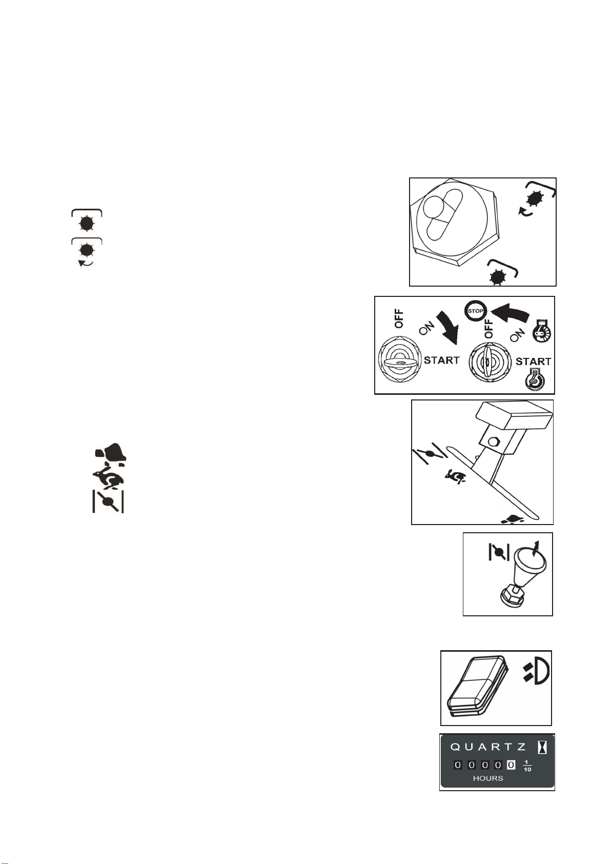
6.1.1 MOWING MECHANISM SWITCH
The switch of the mowing mechanism switches on th electromagnetic clutch whose pulley transfers the drive from the engine by means of the V-belt
to the pulley of the mowing mechanism. The switch is locked in "OFF" position against an unwanted switching on. To switch on, it is necessary to pull
out a bit the switch lever and tip it to the "ON" position.
OFF
ON
6.1.2 SWITCH BOX
The key has 3 positions:
OFF - ignition switched off
ON - ignition switched on
START - engine starting
6.1.3 GAS CONTROL LEVER
It controls the engine revolutions.
The individual positions of the lever are, as follows:
MIN Engine idle running
MAX Engine max. revolutions
CHOKE * Engine cold start
* This gas control lever is only provided in machines equipped with the BS15, TE 17 and H 16 engine.
6.1.4 CHOKE
It enables the start of the cold engine. The machines equipped with the BS15, TE 17 and H 16 engine
are not provided with the independent choke.
6.1.5 BUZZER
After the grass collecting bin is full, the circuit is closed by means of a flap on the rear plate
of the bin and the buzzer sounds. However, the mowing mechanism drive is not disengaged.
6.1.6 HEADLAMP SWITCH
The headlamps placed in front on the bonnet are turned on and off by a switch positioned
together with other switches by the steering wheel.
6.1.7 ENGINE HOUR METER
The engine hour meter is installed in dependence on the machine version.
It is in operation only with the ignition switched on and
the seat switch switched on (automatically by the weight of the operator).
Any manipulation with the engine hour meter means
the loss of guarantee. If a failure of the meter occurs, inform Your service immediately.
15
MACHINE CONTROL ENGLISH
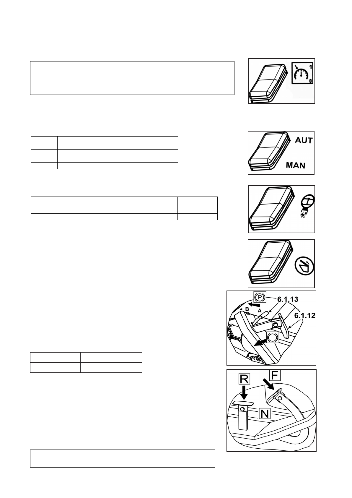
6.1.8 CRUISE CONTROL SWITCH
The cruise control switch is installed in the machine in dependence on its version.
6.1.9 AUT/MAN SWITCH
The AUT/MAN (AUTOMATIC-MANUAL) switch is installed in the machine in dependence on its version. When it is set to the "MAN" position, it is put
out of the operation and the mowed mass may accumulate in the discharge tunnel. That is why the "MAN" position is only determined for a short-term use
at the finishing of mowing of very small remainders of area. When it is set to the "AUT" position, the function of mowing is automatically switched off at
the fill-up of the grass collecting bin.
Position Grass collecting bin is full Mowing mechanism
AUT NO ON
AUT YES OFF
MAN NO ON
MAN YES ON
6.1.10 RESET SWITCH
The RESET switch is installed in the machine in dependence on its version. It serves for the restoration
of the AUT/MAN function. It is operative after discharging the grass collecting bin.
AUT/MAN Switch of mowing RESET switch was Drive of mowing
switch position mechanism was depressed mechanism
all the time on
AUT YES YES ON
The RESET switch is not operative at any different setting of switches.
6.1.11 SWITCH OF GRASS COLLECTING BIN DUMPING
The switch of the grass collecting bin dumping is installed in the machine in dependence on its version.
The switch has two positions:
- LIFTING
- LOWERING
The end positions of the bin in the lifted or normal position are secured with a safety clutch.
At lifting or lowering the bin, keep the switch depressed. As soon as the end position is reached,
release the switch immediately, otherwise a breakdown of the electrical installation is threatening.
6.1.12 BRAKE
When the brake pedal is fully stepped on, the mowing machine is braked to a stop.
Never use the brake simultaneously with the function of the travel -
a damage of the gearbox is threatening.
6.1.13 PARKING LEVER
The parking brake lever has 2 positions. Before shifting the lever into the "B" position,
step on the brake pedal. Lock the lever in the "B" position by turning it round a slight amount.
The disengaging of the parking brake is executed by stepping on the brake pedal,
at this the brake lever pawl is automatically released.
AOFF
BON
6.1.14 TRAVEL PEDAL
It controls the drive of wheels and machine travel speed in both
directions.
Forward drive: Step on slowly the pedal with the toe in the "F“ direction.
The bigger stepping on the higher speed and vice versa.
Backward drive: Step on slowly the pedal with the heel in the "R“ direction.
The bigger stepping on the higher speed and vice versa.
As soon as the pedal is released, it returns automatically into the "N“ (neutral) position
and the machine stops. The travel pedal is equipped with a safety switch which will
prevent from starting the engine if the pedal is stepped on.
16
WARNING !!!
The cruise control is only in the operation with the ignition switched on. Never switch it off by mere stepping
on the brake pedal as the cruise control function would be kept with the next stepping on the travel pedal
- hazard of an injury is threatening. Use the cruise control at the long and direct travels only.
Before any change of the travel direction switch the cruise control off by the switch.
WARNING !!!
The change of the drive direction is only possible after the machine stops.

MACHINE CONTROL ENGLISH
6.1.15 BY-PASS LEVER
The by-pass lever serves for disengaging the gear of the rear wheels drive.
It has two positions:
Position Rear wheels drive Use
0 OFF machine pushing, engine in standstill
1 ON drive, engine running
* The location of the lever in the machine is dependent on the machine version.
6.1.16 DIFFERENTIAL LOCK PEDAL
This pedal is installed in the machine in dependence on its version.
It has 2 positions. To engage the lock, step on the pedal with Your heel,
it will be disengaged automatically after releasing the pedal.
6.1.17 MOWING MECHANISM HEIGHT SETTING-UP LEVER
It serves for setting up the mowing mechanism height above the ground.
It has 7 working positions corresponding to the height of mowing 3 up to 9 cm.
The bigger the number of the lever position the higher vegetation remains after the mowing.
When driving the machine without mowing the lever must be set in the position "7".
6.1.18 MULCHING FLAP LEVER
This lever is installed in the machine in dependence on its version. It has 2 positions.
When it is set in the "A" position, the discharge tunnel is closed. This enables the function
of mulching in the course of which the mowed grass is spread out under the mowing machine.
The vegetation can be mulched maximally by 1/3 of its height. The height of vegetation after
mowing must remain 5 cm minimally. To collect the mowed grass into the bin, shift the lever
to the "B" position in order to change over the mulching flap. Before shifting the lever stop,
let the mowing mechanism clean out, shift the lever and carry on in driving. If this procedure
is not observed, it can result in an imperfect functioning of the flap and clogging
of the discharge tunnel. After finishing the work, clean the mowing mechanism and discharge
tunnel thoroughly to ensure the correct functioning of the mulching flap.
6.1.19 CLOSURE OF FUEL SUPPLY
The AJ 102 machines equipped with the BS15 engine have not the fuel pump, that is why they are provided with the closing cock. The cock serves for
prevention of a spontaneous inflow of the petrol into the engine in case of the carburettor untightness as the tank is placed higher than the carburettor.
The cock should be closed at any longer stopping of the engine.
17
WARNING !!!
Use the differential lock only if driving directly forward, and only in case
of necessity (slippage). Never use the lock when changing driving direction.
Not observing these rules may result in a serious damage to the gearbox!

MACHINE CONTROL ENGLISH
6.2 OPERATION AND ATTENDANCE
Machine safety protection
The mowing machine is equipped with safety contacts which are closed by:
- switch placed under the seat
- switch of the grass collecting bin suspending, contingently of the deflector
- switch of the grass collecting bin fill-up
- switch of the travel pedal
The engine will automatically stop if the driver leaves the seat. The engine can only be started up if the mowing mechanism is switched off and the grass
collecting bin is suspended, contingently the deflector, which prevents from the entering of the mowed grass into the inlet tunnel of the collecting bin
during mulching, is put in.
6.2.1 SUSPENSION OF GRASS COLLECTING BIN
Grasp the grass collecting bin with both hands and lift it. Tilt it to be reclined under the angle of 40° and suspend it on two brackets located on the
machine rear side. The tops of labels having the shape of yellow triangles must be opposite one to the other (see the chapter 4.2.7).
6.2.2 ENGINE STARTING
• Check the petrol level in the tank.
• Open the petrol supply closure - valid only for the BS15 engines having power output of 15,5 HP
• Sit down onto the machine seat comfortably, shift the mowing mechanism height setting-up lever 6.1.17 to the position "7".
• Set the mowing mechanism switch 6.1.1 to the "OFF" position.
•Caution, do not step on the travel pedal 6.1.14.
• Set the gas control lever 6.1.3 to the "MAX“ position - only at machines with engine having power output of 16 HP and higher.
• Set the gas control lever 6.1.3 to the "CHOKE“ position - only at machines with the BS15 engines having power output of 15,5 HP.
• Pull out the choke 6.1.4 - only at machines with engine having power output of 16 HP and higher.
• Do not manipulate the mowing mechanism height setting up lever 6.1.17.
• Turn the ignition key 6.1.2 to the "START“ position.
The time of starting must not exceed 10 seconds – if this time is exceeded a damage to the battery threatens.
• The engine "is running" - let loose the ignition key. The key will automatically return to the "ON" position.
• Progressively push the choke 6.1.4 inwards - only at machines with engine having power output of 16 HP and higher.
• Set the gas control lever 6.1.3 slowly to the "MIN" position (reduce the engine speed).
• Let the engine run for several minutes before turning on the mowing mechanism.
6.2.3 ENGINE STOPPING
• Set the gas control lever 6.1.3 to the "MIN" position.
• Turn off the mowing mechanism by the switch 6.1.1 (see the chapter 6.2.4).
• If the engine is overheated, let it running for a while at minimum revolutions.
•Turn off the engine by the key 6.1.2 rotation to the "STOP" position and remove the key from the ignition.
6.2.4 MOWING MECHANISM TURNING ON AND OFF
a) Turning on
• Set the gas control lever 6.1.3 to the "MAX" position.
• Set the working position of the mowing mechanism and with it also the height of mowing by the mowing mechanism height setting-up lever (see the
chapter 6.1.17 and 6.2.5).
•Set the mowing mechanism switch 6.1.1to the "ON" position.
The mowing mechanism will be switched on provided:
-operator is sitting on the machine seat
-grass collecting bin is suspended, contingently the deflector is put in
- AUT/MAN switch 6.1.9 is in the "AUT" position, and the "RESET" switch 6.1.10 was depressed after discharging the grass collecting bin - valid
only for models equipped with the AUT/MAN switch
- AUT/MAN switch 6.1.9 is in the "MAN" position - valid only for models equipped with the AUT/MAN switch
b) Turning off
•Set the mowing mechanism switch 6.1.1 to the "OFF" position.
• If the driver leaves the seat, the engine will stop automatically, and with this also the rotation of mowing knives.
18
DANGER !
Never leave the running engine in a closed or badly ventilated room. The exhaust fumes containing the carbon monoxide are very dangerous.
Keep Your hands, legs and loose clothes out of the reach of moving parts and of the exhaust.
WARNING !!!
Never stop the engine by a mere getting off the seat, as the key left in the ignition switch may cause a fault of the electrical installation.
Always rotate the key to the "OFF" position and remove it from the switch box.
IMPORTANT
Before turning the ignition off, reduce the engine revolutions to the slow speed in case the self-ignition will occur,
not observing this instruction may result in a damage to the engine and exhaust.
WARNING !!!
Never switch off the mowing mechanism by mere getting off the seat. Unless You switch over the ignition key from the "ON" position
to the "OFF" (STOP) position, the part of the electrical installation is still live and this may cause its fault.

MACHINE CONTROL ENGLISH
6.2.5 MOWING MECHANISM HEIGHT SETTING-UP
Shift the mowing mechanism height setting up lever of 6.1.17 upwards if You want to set up the mowing mechanism higher above the ground, or shift the
lever downwards if You want to set up the mowing mechanism closer to the ground.
The position "1" is used for following the terrain unevenness. Do not use this height setting up permanently as there is a danger of increased wear of the
mowing mechanism parts.
The mowing mechanism is equipped with 4 traversing wheels which lift the frame with mowing mechanism in case of a terrain unevenness and thus they
serve as the protection of mowing knives against a damage.
6.3 TRAVEL
Before the start of travelling step on the brake pedal 6.1.12 to make Yourself sure that the parking brake is disengaged. The parking brake lever 6.1.13 must
not stay in the "B" position! The by-pass lever 6.1.15 must be set in the position "1", i.e. the by-pass of travel must be disengaged. At travelling to the place
where the mowing is to be carried out, the mowing mechanism must be switched off and lifted to the highest position, i.e. the lever of the mowing mecha-
nism height setting-up must be in the position "7". At crossing the obstacles higher than 8 cm (kerbs, etc.) it is necessary to use the ramps in order to pre-
vent from a damage to the mowing mechanism and gearbox.
Carry out the drive itself in the following way:
• Decrease the speed of the engine by shifting the gas control lever 6.1.3 to the "MIN" position.
• At moving off, step on the travel pedal 6.1.14 slowly in accordance with the desired direction of the drive - at the fast stepping on the pedal there is
a danger of injury.
• The change of the drive direction from forward to backward or vice versa is only possible after the machine is stopped. If the machine is not stopped there
is a danger of the gearbox failure.
• Never use the travel pedal and brake pedal simultaneously - otherwise there is a danger of the gearbox failure.
6.4 TRAVEL SPEED AND MOWING OF GRASS
Set the gas control lever 6.1.3 to the "MAX“ position. Set up the mowing mechanism height by the lever 6.1.17 (see the chapter 6.2.5).
There is a generally accepted rule that the more wet, higher and denser grass the lower the speed is to be used. If the speed of the machine is too high,
or in the case of a heavy load, the turning speed of knives decreases, the quality of mowing goes down and the clogging of discharge tunnel may occur.
If the grass is too high, the mowing should be done several times. The first cut in the maximum height, contingently with reduced width of mowing, and
the next cut already in required height. We recommend to mow in the longitudinal as well as cross direction. The overlapping of the machine preceding
cut enables to increase the efficiency of knives, and also the feature of the mowed area will be improved.
Driving on an uneven surface may result in variation of the speed.
With respect to the conditions, we recommend the following speeds:
6.5 TRAVEL ON A SLOPE
This mowing machine may operate on the slopes up to the gradient of 10° (17%). When working on a slope use always lower speed of travel. Travel only
perpendicularly to the contour line, i.e. upwards and downwards. The travel along the contour line is not permitted. Control the speed of travelling by means
of the gear change lever. Travel downhill and across the obstacles at lower speed. The change of direction and turning around on a slope requires increased
caution. When stopping the machine on a slope, always use the parking brake. When the machine is being overloaded on slopes of bigger gradient than
10° (17%), it may result in a serious damage to the gearbox. The machine manufacturer does not bear any responsibility for a defect resulted from such use
of the machine.
6.6 DISCHARGING OF GRASS COLLECTING BIN
•Stop, apply the brake, and use the parking brake if You are on a slope.
•Switch off the mowing mechanism by the toggle switch 6.1.1.
If the AUT/MAN switch is installed in the machine, leave this switch in the "AUT" position.
•Set the gas control lever 6.1.3 to the "MIN" position.
•At machines equipped with the manual lifting and lowering of the grass bin, shift the lifting lever 18 (see the chapter 4.2.6) up fully, and then use this lever
to tilt the bin. Leave the bin to discharge freely, release it progressively and return it to the basic position.
•At machines equipped with the device for mechanical lifting and lowering of the grass bin, depress the switch to the "LIFTING" position and keep it
depressed until the bin is entirely tilted. After the desired position is reached, release the switch and wait until the bin is discharged. Then switch over
the switch to the "LOWERING" position and keep it depressed until the bin is entirely lowered. After the home position is reached, release the switch.
•After lowering the bin into the home position, switch on the mowing mechanism by the toggle switch 6.1.1. If the machine is equipped with the RESET
switch (6.1.10), depress this switch to activate the mowing mechanism.
19
WARNING !!!
The machine stopping is only possible by a gradual releasing of the foot from the travel pedal and then by stepping on the brake pedal. At stepping
on the brake pedal, the travel pedal is automatically moving to the neutral position. At this, the braking distance is shorter than 2 m.
Vegetation condition Recommended speed
high, dense and wet 2 km/hour
average conditions 3 – 5 km/hour
low, dry vegetation < 5 km/hour
travel with disengaged mowing mechanism < 7 km/hour
This manual suits for next models
1
Table of contents
Languages:
Other Seco Group Lawn Mower manuals

Popular Lawn Mower manuals by other brands


Craftsman
Craftsman 917.377042 owner's manual

Husqvarna
Husqvarna Automower 535 AWD quick guide

Jacobsen
Jacobsen AR3 Safety, operation and maintenance manual

Meec tools
Meec tools 721-396 User instructions

Yard Machines
Yard Machines 580 Series Operator's manual

Poulan Pro
Poulan Pro PO10530LT Repair parts manual


