Security Chimneys HE43-2 User manual

HE43N -2
HE43BN-2
SAVE THESE INSTRUCTIONS
FOR FUTURE REFERENCE
This installation manual will enable you to obtain a safe, efficient
and dependable installation of your fireplace system. Please read
and understand these instructions before beginning your installation.
Do not alter or modify the fireplace or its components under any cir-
cumstances. Any modification or alteration of the fireplace system,
including but not limited to the fireplace, chimney components and
accessories,mayvoidthewarranty,listingsand approvalsofthis system
and could result in an unsafe and potentially dangerous installation.
Security Chimneys International wood-burning fireplaces are designed
for use as a supplemental heater. They are not intended for continuous
use as a primary heat source.
INSTALLATION AND
OPERATION INSTRUCTIONS
WARNINGS
•
Hot! Do not touch! The glass and
surfaces of this appliance will be hot
during operation and will retain heat
for a while after shutting off the appli-
ance. Severe burns may result.
•
Carefully supervise children in the
same room as appliance.
HE43-2
MODEL
WARNINGS
•
The fireplace cannot be operated without doors
or firescreens. Consult your dealer to select the
correct replacement door(s) or firescreen(s).
•
Important! To assure proper alignment of glass
doors: Install this fireplace in a square and
plumb condition, using shims as necessary at
sides and/or bottom.
•
Install the fireplace only as described in these
instructions.
PIHE43-2 REV. 2 06/2010
EPA Low-Mass Wood-burning Fireplace Phase 2 Qualified
43" Wood-Burning Fireplaces
P/N 506065-07 REV. B 06/2010
Listed to standards:
ULC-S610 & UL-127
ASTM 2558
Report No. 192-5237
Intertek

2
WARNING
NEVER use gasoline, gasoline-
type lantern fuel, kerosene,
charcoal lighter fluid, naphtha,
engine oil or similar liquids to
start or “freshen up” a fire in this
fireplace. Keep any flammable
liquids a safe distance from the
fireplace at all times.
WARNING
The bottom refractory can be
crackedbyexcessive abusesuch
as tossing heavy logs onto the
grate or gouging with fireplace
tools. Exercise caution when
adding wood to your fireplace.
WARNING
Neither the manufacturer nor the
seller warrants “smoke free”
operationnorare weresponsible
for inadequate system draft
caused by mechanical systems,
general construction conditions,
inadequate chimney heights,
adverse wind conditions and/or
unusual environmental factors
orconditionsbeyondourcontrol.
CAUTION
Usecarewhenselecting window
treatments for windows located
near the fireplace. Avoid using
combustible flowing window
treatments such as curtains
on nearby windows that are of
sufficient length to be blown in
front of an open flame when the
window is opened.
Keep any combustible furniture,
materials or decorative pillows
at least 48" (1219 mm) from the
front fireplace opening.
WARNING
Neverleavechildren unattended
when there is a fire burning in
the fireplace.
WARNING
Never leave your fireplace unat-
tended while it is burning.
IMPORTANT
When burning wood, use SOLID
NATURAL DRY WELL-SEASONED
WOOD ONLY. Hardwoods are
recommended (soft woods tend
to burn very quickly).
• DO NOT burn treated wood,
charcoal, coal, trash, card-
board, driftwood, woods dipped
in tar, Christmas tree greens,
pitch, pine tar, creosote, chemi-
cal chimney cleaners, flame
colorants, polystyrene packag-
ing,woodproductswithsynthetic
binders(i.e.plywood). Plywood,
lumber and other misc. materi-
alscan produceabnormallyhigh
temperatures, sputtering and
smoking fires and may contain
hazardous chemicals to treat
insects and fungus.
• Burning unapproved fuels can
produce excessive tempera-
tures, beyond the design capa-
bilities of the fireplace and may
produce excess sparks or may
contain hazardous chemicals.
Burning unapproved fuels can
result in a chimney fire, a house
fire, personal injury, death or
loss of property.
IMPORTANT! GENERAL SAFETY
PRECAUTIONS. READ AND
UNDERSTAND THESE SAFETY
RULES BEFORE YOUR FIRST FIRE.
WARNING
Be careful adding wood fuel to the
fireorhandlingfireplacetoolssuch
as shovels, tongs or pokers.
WARNING
To avoid the risk of damaging
fireplace materials and increas-
ing the risk of fire, do not use the
fireplace to cook or warm food.
WARNING
Never modify or alter your fire-
place system in any way. To do
so may create a potential fire
hazard and void the limited war-
ranty, listings and approvals of
this system.
WARNING
Alwaysensurethattheairinletto
the fireplace is free from debris
and any other obstructions that
can block the entrance of air.
WARNING
The HE43-2 fireplace must be
installed with an outside air kit
intake, which is included with
the fireplace.
WARNING
THE FIREPLACE MUST BE OPER-
ATED WITH THE DOORS FULLY
OPENED OR DOORS FULLY
CLOSED. IF THE DOORS ARE LEFT
PARTLYOPENED,GASANDFLAME
MAY BE DRAWN OUT OF THE FIRE-
PLACEOPENING,CREATINGRISKS
OF BOTH FIRE AND SMOKE. IF
THE UNIT IS OPERATED WITH THE
DOORS FULLY OPENED, THE FIRE
SCREEN MUST BE USED.
WARNING
THIS FIREPLACE HAS NOT BEEN
TESTED WITH AN UNVENTED
GAS OR A FIREPLACE INSERT.
TO REDUCE RISK OF FIRE OR
INJURY, DO NOT INSTALL AN
UNVENTED GAS LOG SET OR
FIREPLACE INSERT OR OTHER
PRODUCTS NOT SPECIFIED FOR
USE WITH THIS FIREPLACE.

3
TABLE OF CONTENTS
Safety Rules.......................................Page 2
Introduction .......................................Page 3
Parts Required ..................................Page 3
Optional Equipment............................Page 3
EPA Qualified .....................................Page 3
Operating The Fireplace .....................Page 4
Fuel ....................................................Page 4
First Fires ...........................................Page 4
Building a Fire ....................................Page 4
Outside Air Register ..........................Page 5
Refueling............................................Page 5
Closing the Doors ..............................Page 5
Smoking – Causes And
Troubleshooting ..............................Page 5
Important Cautions ............................Page 5
Maintaining Your Fireplace.................Page 6
Creosote.............................................Page 6
Chimney Maintenance........................Page 6
Dealing With A Chimney Fire..............Page 6
Top Baffle Removal ............................Page 6
Door Frame Care................................Page 6
Disposing of Ashes ............................Page 6
Refractory Replacement.....................Page 7
Door Adjustment................................Page 7
How to use the retractable doors
and firescreens ...............................Page 7
Glass Care - Replacement..................Page 8
Glass Care - Cleaning.........................Page 8
Gasket Replacement .........................Page 8
Fireplace Installation .........................Page 8
Locating the Fireplace .......................Page 8
Preinstallation ...................................Page 9
Precautions........................................Page 9
Adjacent Wall .....................................Page 9
Enclosure / Chase ..............................Page 9
Mantel ...............................................Page 10
Hearth Extension Requirements ........Page 10
Cold Climate Installations ..................Page 10
Fireplace and Framing Dimensions ....Page 11
Insulated Chase Construction ...........Page 12
Fireplace Facing .................................Page 12
Outside Air Assembly ........................Page 13
UZY5 Blower Kit.................................Page 14
Forced Air Heating Kit .......................Page 14
Chimney System................................Page 15
Chimney Installation Instructions ......Page 16
Offset Chimney Installation ................Page 17
Angled Wall Radiation Shield .............Page 19
Universal Roof Support......................Page 20
Chimney Chase And
Multiple Terminations......................Page 20
Chimney Adaptor ...............................Page 20
Installation Accessories .....................Page 21
Chimney Components Lists ...............Page 22
Specifications.....................................Page 23
Clearances .........................................Page 23
Replacement Parts.............................Page 24
Product Reference Information..........Page 26
CONGRATULATIONS!
When you purchased your new fireplace, you joined the ranks of thousands of individuals
whose answer to their home heating needs reflects their concern for aesthetics, efficiency
and our environment. We extend our continued support to help you achieve the maximum
benefit and enjoyment available from your new fireplace.
Thank you for selecting a Security Chimneys International fireplace as the answer to your
home supplemental heating needs.
THE FIREPLACE
INTRODUCTION
The HE43-2, EPA Low-Mass Wood-burning
Fireplace Program qualified, is an energy effi-
cient, heat circulating fireplace. You will receive
a lifetime of comfort and enjoyment from your
fireplaceprovided it is installed, maintainedand
operated properly.
• Please read these instructions and retain
this manual for future reference.
• Before beginning the fireplace installation,
consult the local authorities to obtain your
building permitandcheckyourlocalbuilding
codes. Installthe fireplace onlyas described
in these instructions and using only Security
Chimneys International components.
• The HE43-2 fireplace is NOT intended for
use with an unvented gas log set. Do not
use a fireplace insert or any other product
with this fireplace unless it is specified by
Security Chimneys International for use
with this appliance. Failure to follow these
instructionswillvoidthe certificationand the
warranty of the fireplace and may result in
an unsafe installation.
• These appliances are NOT approved for
Manufactured Home installations.
PARTS REQUIRED
Fireplace Model HE43-2
•8"diameterchimney-ModelSecureTemp™
ASHT1", SecureTemp S-2100+ orAC manufac-
tured by Security Chimneys International only,
including:
- Chimney lengths
- Elbows (where necessary)
- Associated components as per these
Installation Instructions
•Door (included)
•Outside Air Kit (included)
OPTIONAL EQUIPMENT
•Additional Equipment (optional)
- Trim Kit available in Nickel
- UZY5 blower
- VRUW Blower motor speed control
- Forced Air Heating Kit
u
u
Ifinstalled,thisappliancenolongerqualifies
for EPA Low Mass Wood-burning Fireplace
Program.
EPA WOOD-BURNING FIREPLACE
PROGRAM QUALIFIED
This appliance has met the U.S. Environmental
Protection Agency (EPA) Low Mass Wood-
burning Fireplace Program Phase 2 emission
level (g/kg), as per test protocol ASTM 2558
"standard test method for determining particu-
late matter emissions from fires in low mass
wood-burning fireplaces".
Fresh FireTM
Burn System
1- Air is diverted under the front of the grate,
gaining heatfromtheemberandashmaterial
for more efficient combustion.
2- Cool air is deflected to prevent cooling
of the fire, so that high temperatures are
maintained.
3- Efficient combustion leads to lower emis-
sions,becausethehighertemperatures burn
up more volatile gasses and particulates.
4- Exhaust air is effectively pulled into the
chimney, and heat from the fire is circulated
into the living space.
1
2
3
4
NOTE: DIAGRAMS & ILLUSTRATIONS ARE NOT TO SCALE.

NOTE: DIAGRAMS & ILLUSTRATIONS ARE NOT TO SCALE.
4
Building A Fire
(starting and maintaining a fire)
To start a fire, place several crumpled up balls
of newspaper in the firebox. Place small dry
pieces of kindling on top of the paper, criss-
crossingthekindlingsothatthereare airspaces
in between. Keep the fuel far back enough
so that air can get underneath. Open the air
controls fully and light the newspaper. Once
the newspaper and the kindling is well ignited,
close the firescreens. Once the kindling fire is
well established, cord wood can be added (see
How To Use The Outside Air Register section for
proper operation of the air controls).
The unit will burn best with 2-3 pieces of cord
wood spaced 1/2 to 1 inch apart and allowing
air to get under the fuel. Criss-crossing or ar-
ranging the fuel so that air can get underneath,
will help the fire to get started easily. The unit
should be operatedwiththeaircontrolfullyopen
long enough to get the cord wood well ignited.
For the Fresh FireTM system to burn efficiently,
air must flow through the bottom of the grate
and up in between the logs. Do not let ashes
stack up to a height which will obstruct the
opening between the base of the firebox and
the bottom of the log retainer.
OPERATING THE FIREPLACE
Fuel
USE SOLID NATURAL WOOD FUEL ONLY.
The HE43-2 fireplace is designed to work best
when fueled with seasoned natural wood only.
Hardwoods are preferredto softwoodssincethe
energy content of wood is relative to its density.
Hardwoods will result in a longer burning fire
and less frequent refueling. A moisture content
of 15% to 20% (seasoned) is recommended.
Wood that has been cut and split and let to
dry under a cover for a period of one year will
usually meet that criteria. The required drying
time will vary depending on the climate. Wood
that is packed tight together will take longer to
dry. Seasoned wood is darker in color than wet
wood and will have visible cracks in the grain
on the ends. Excessively wet wood will be dif-
ficult to burn and will result in lower efficiency,
increased creosoting and deposits on the glass
and in the chimney. Excessively dry wood will
burn well but will also have higher emissions
and shorter burning time.
Do not burn scrap or garbage, treated wood or
wood such as driftwood from the ocean which
has been exposed to salt or other chemicals.
Salt or chemicals can corrode the firebox and
chimney. Do not burn large amounts of paper,
cardboard,Christmas tree branchesor building
constructionmaterials. Intensefiringwiththese
materials may overheat the fireplace, causing
damage to the unit, a fire or even possibly ignit-
ing a chimney fire if the chimney is creosoted.
Burningunapprovedfuel,resultingin excessive
pollutantsbeingemitted,may be prohibitedand
subjectto afine orother penalty by the authority
having jurisdiction in your area.
Processed firelogs can be used. Refer to firelog
warnings and caution markings on the packag-
ing prior to use.
First Fires
Before using the fireplace make sure to
remove the plastic wrapping on plated door.
Remove any glue residue left by the label
using mild soap.
The first five or six fires should be small fires of
short duration (about 30 to 60 minutes). This
will help cure the refractory bricks. During the
first few fires of this appliance there may be
some odor and smoke due to the curing of the
paint, dust accumulation and burning off of
lubricants used in the manufacturing process.
It may set off a smoke alarm located in the same
room. For this reason the room should be well
ventilated for the first few fires.

NOTE: DIAGRAMS & ILLUSTRATIONS ARE NOT TO SCALE. 5
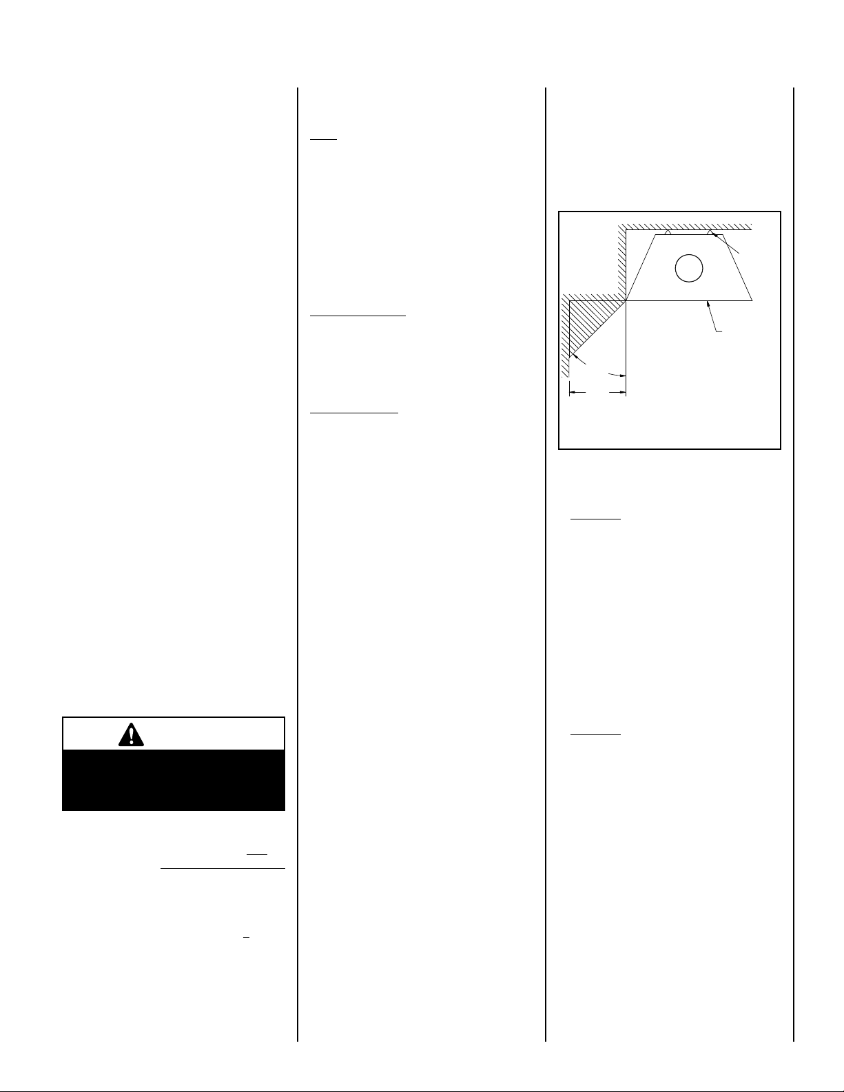
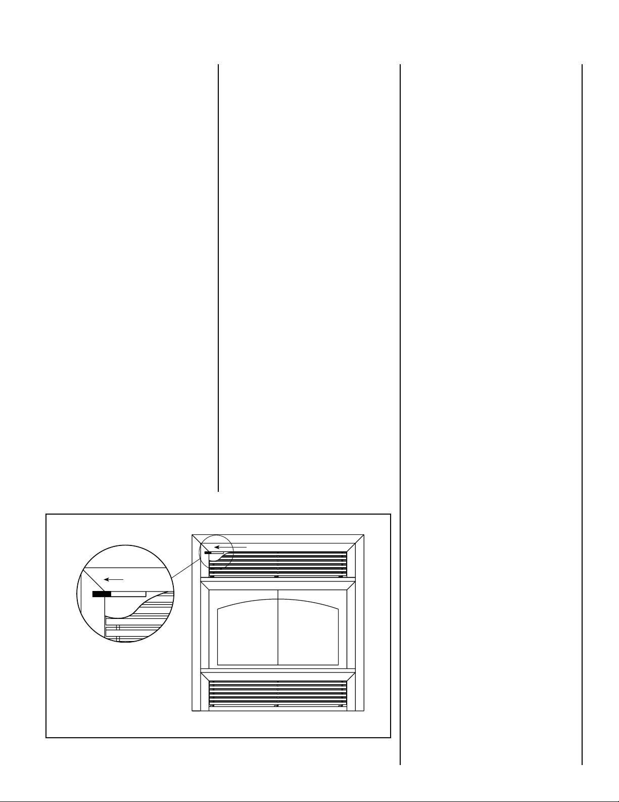
Figure 1 - Outside air Register
D. Wet wood
Wetor tarredwoodwillsmoulderandsmoke
instead of burning properly. Your dealer can
help you determine if you have properly
seasoned wood for burning.
E. Dirty or blocked chimney
Check to make sure the chimney is clear and
clean. If dirty call a certified chimney sweep
or use a properly sized chimney brush to
clean.
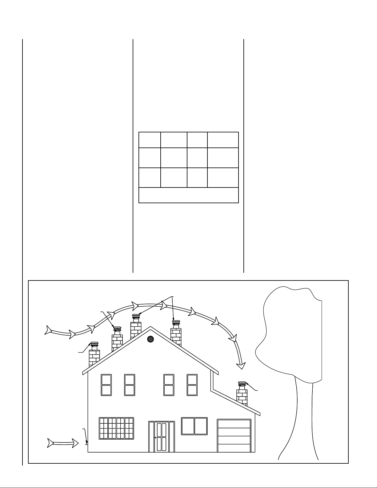
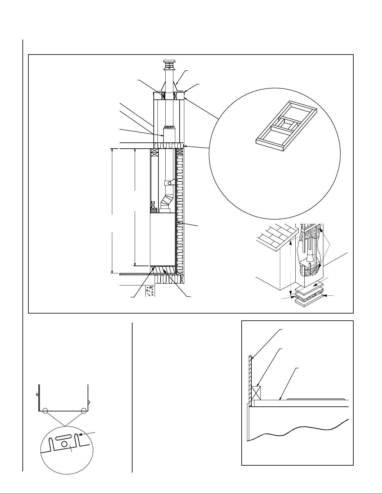
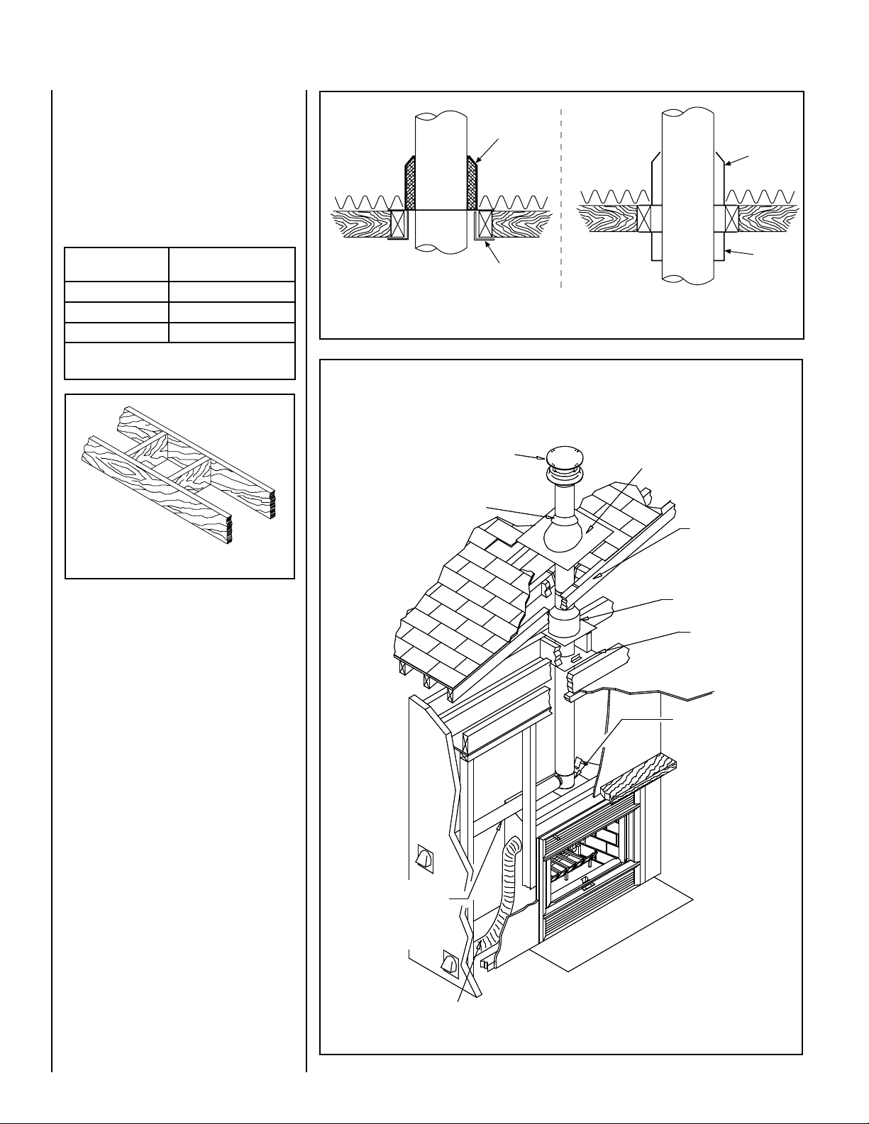
F. Chimney not long enough
The minimum chimney height is twelve (12)
feet(3.7m)notincludingthefireplaceheight.
The chimney must extend at least three (3)
feet (915 mm) above its point of contact
with the roof and at least two (2) feet (610
mm) higher than any roof or wall within ten
(10) feet (3 m) of it. When installed with
one offset, the minimum chimney height
is fifteen (15) feet. Additional height will
increase draftandwilldecreasethe tendency
to smoke.
G. Poor chimney draft
With no fire, there should be sufficient draft
to exhaust cigarette smoke introduced under
the chimney. Chimneys installed against an
outside wall without protection may generate
back draft problems which will cause start-up
problems. To prevent this, open a nearby
window, roll up a piece of paper and light it.
Then, hold it in the upper part of the firebox
to warm up the chimney. Wait until the draft
is sufficient, then start the fire.
IMPORTANT CAUTIONS
A. Donotblockthehotairvents tothefireplace
as this will cause the fireplace to overheat.
B. Never use gasoline, gasoline-type lantern
fuel, kerosene, charcoal lighter fluid, or
similar liquids to start or ‘freshen up’ a fire
in this fireplace. Keep all such liquids well
away from the fireplace while it is in use.
C. Do not burn coal. The sulphur in coal will
corrode the firebox and chimney.
D. Keep combustible materials at least 48”
(1.2 m) away from the front of the fireplace
opening.
E. Never leave children unattended when
there is a fire burning in the fireplace.
F. Do not use the HE43-2 as an incinerator
to burn paper, cardboard or construction
material such as pressed wood, plywood
or lumber. Use only untreated wood. Wood
protectors, metallic paper, coal, plastic,
waste, beach wood, Christmas tree, sul-
phur and/or oil will damage the fireplace.
G. Donotburndriftwood whichhasbeenin the
ocean or salt water. The salt will corrode
the firebox and chimney.
H. Do not burn wood in the area in front of
the log retainer.
I. Do not allow the wood to smoulder or burn
without flame, since this will produce
excessive creosote in the unit as well as
increased particulate emissions.
Push to open
Push to open
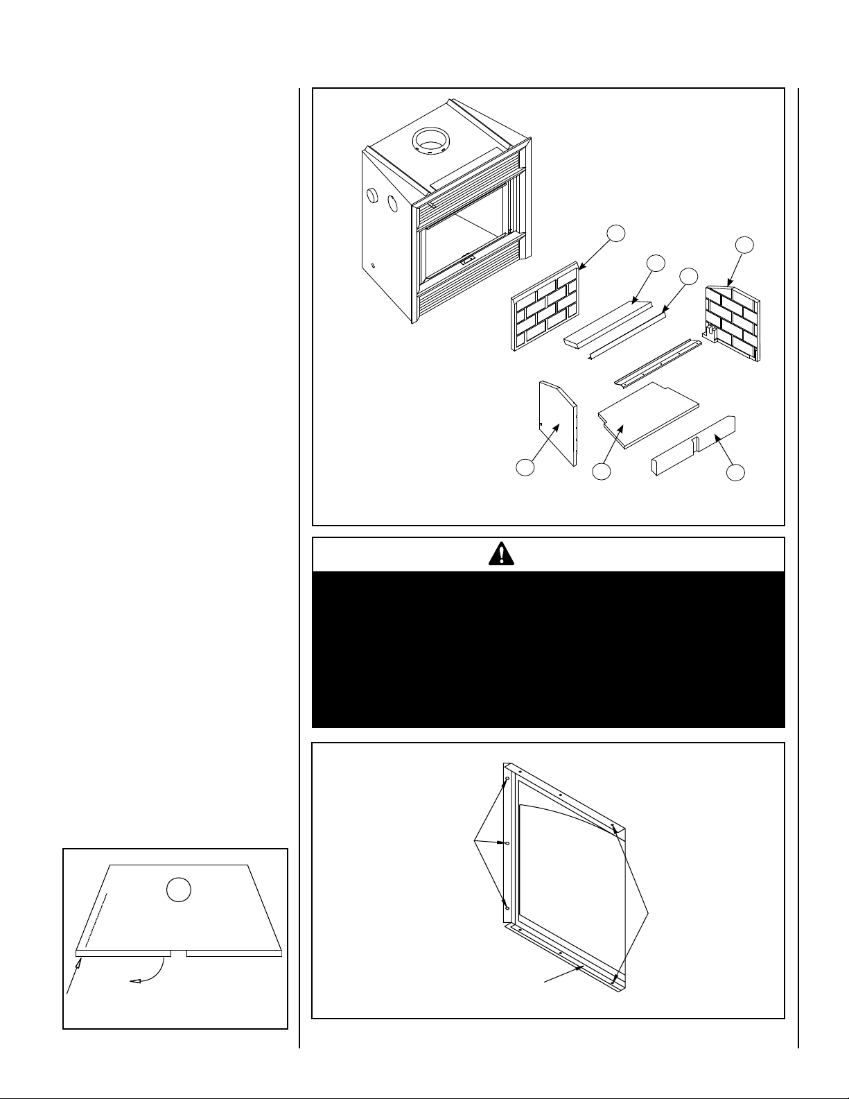
HOWTOUSETHEOUTSIDEAIRREGISTER
(FIREPLACE)
The outside air register is located on the up-
per left part of the top louver. The outside air
register supplies oxygen to the fire and allows
control of the fire when the doors are closed.
The fresh air must come from outside the house
(the air intake must not draw air from inside the
house). This will minimize negative pressure in
the house. The more you slide the register to
the left, the more fresh air into the firebox and
the more accelerated combustion you will get
(see Figure 1). When starting a fire, the register
should always be fully opened.
Forinformationonwhenyoushouldstartclosing
the register, see "Refueling" section.
REFUELING
The HE43-2 fireplace will operate best if at-
tention is given to operating the unit with the
outside air register fully opened (see Figure
1)after refueling in order to bring the firebox
and the chimney system up to their optimum
operating temperature. Combustion efficiency
is relative to firebox temperature. To obtain this
temperature, the fireplace must be operated
with the primary air fully opened during 10 to
20 minutes after reloading, depending on the
heat and on the moisture content of the wood.
Onceyouhavereached the desiredtemperature,
the outside air register control can be set to a
medium setting. The benefit of this technique
will be cleaner glass, less creosoting, greater
efficiency and the most pleasing fire for your
enjoyment.
Settheairregistertothefullopenpositionbefore
opening the doors to reduce the possibility of
smoke entering the home from the fireplace.
CLOSING THE DOORS
As soon as a layer of embers covers the surface
under the log retainer, it is possible to close
the doors with the outside air register opened.
Closing the doors prematurely may result in:
• Thereboxllingwithsmoke;
• Theameintensitycutsdownexcessively.
Meaning the fireplace is not hot enough to
close the doors.
SMOKING –
CAUSES AND TROUBLESHOOTING
To reduce the likelihood of smoking when
opening the door, set the outside air register to
the left before opening the door. Your fireplace
has been designed and tested to provide smoke
free operation. Occasionally, there may be a
small amount of smoking upon lighting the fire,
until the chimney heats up but this should not
continue. If the fireplace continues to smoke
it is probably for one of the following reasons:
A. The doors are partially opened
When you open the doors, open them
completely.
B. Negative pressure in the house
As the fire burns, air goes up the chimney.
This air must be replaced through leakage
into the house or through the outside air
duct. When operating the HE43-2 fireplace,
open a nearby window temporarily to check
if there is adequate replacement air supply.
C. Fans operating (e.g.: range hood)
Fans such as range hoods or bath fans draw
air out of the house and may actually cause
a negative pressure in the house. Turn off all
fansandopena nearbywindowtodetermine
if this is the cause of the problem.

NOTE: DIAGRAMS & ILLUSTRATIONS ARE NOT TO SCALE.
6
Caution: It is necessary to remove the
baffle from the top of the firebox before
cleaning the chimney.
Dealing With a Chimney Fire
Regular chimney maintenance and inspection
canpreventchimneyfires. Ifyouhaveachimney
fire, follow these steps:
1. Close the fireplace glass doors and the air
inlet.
2. Close the chimney outside air register.
3. Alert your family of the possible danger.
4. If you require assistance, alert your fire
department.
5. If possible, use a dry chemical fire extin-
guisher, baking soda or sand to control
the fire. Do not use water as it may cause
dangerous steam explosions.
6. Watch for smouldering or fire on combus-
tibles next to the fireplace and chimney.
Check outside to ensure that sparks and
hot embers coming out of the chimney are
not igniting the roof.
7. Do not use the fireplace again until your
chimney and fireplace have been inspected
byaqualifiedchimneysweeporafiredepart-
ment inspector.
Top Baffle Removal Prior to Cleaning The
Chimney
Before starting to clean your chimney, we
recommend that you remove the top baffle to
avoid creosote dust collection at the top of the
baffle. Follow these steps to set the top baffle
out of the way:
1. Remove the baffle refractory and it’s iron
anglesupport(gure2);
2. Obstruct the dilution air box inlet, located in
the upper back of the firebox, with a metal
orcardboardsheet;
3.Closethechimneydamperanddoors;
4.Proceedwithchimneysweep;
5. Open the chimney damper before opening
thedoors;
6.Cleanouttherebox;
7. REMOVE the metal or cardboard sheet,
placed in step #2, and re-install the baffle
and it’s iron angle support.
MAINTAINING YOUR FIREPLACE
Creosote - Formation and Need for Removal
When wood is burned slowly, it produces tar
and other organic vapors, which combine
with expelled moisture to form creosote. The
creosote vapors condense in the relatively
cool chimney flue of a slow-burning fire. As
a result, creosote residue accumulates on the
flue lining. When ignited this creosote makes
an extremely hot fire.
The chimney shall be inspected at least twice
a year during the heating season to determine
when a creosote buildup has occurred.
When creosote has accumulated it shall be
removed to reduce the risk of a chimney fire.
When the creosote accumulation is large, a
creosote fire in the chimney can damage the
chimney and overheat the surrounding wood
framing. Creosote formation in a chimney can
be minimized by making sure there is always
visible flame burning, avoid smouldering fires
and by proper refuelling techniques.
Chimney Maintenance
Regular chimney inspection and maintenance
combinedwithproperoperationwillhelpprevent
chimney fires. Keep your chimney clean. Do
not allow more than a 1/16" (1.6mm) build-up
of creosote in your chimney. The amount
of creosote will depend on variables such as
frequency of use and type of fire. We recom-
mend that you:
A. Initially, inspect the chimney system weekly.
By doing this, you will learn how often it will
be necessary to clean your chimney.
B. Have your chimney cleaned by a qualified
chimney sweep. If you wish to clean it
yourself, we recommend using a stiff plastic
or non-metallic brush. If a metal brush is
used, its size should be slightly smaller than
the flue to avoid damaging the chimney. Do
not use a brush that will scratch the stainless
steel interior of the chimney.
C. Do not expectchemicalcleaners to keepyour
chimney clean. The raincap can be removed
forinspectionand/orcleaningofthechimney.
Unscrew the braces which attach the raincap
to the chimney. Using gloves, firmly grip the
upper portion of the rain cap. Turn the cap
and lift it off the chimney.
Figure 2 - Baffle Removal / Chimney Access
WARNING
Disposal of Ashes: Ashes should
be placed in a metal container
with a tight fitting lid. The closed
container of ashes should be
placed on a non-combustible
floor or on the ground well away
from all combustible materials,
pending final disposal. If the
ashes are disposed of by burial
in soil or otherwise locally dis-
persed, they should be retained
in the closed container until all
cinders have thoroughly cooled.
Door Frame Care
Use a glass cleaner and a soft cloth to polish
the frame. Do not use abrasives such as steel
wool or steel pads for they may scratch the
door frame finish.
Disposing Of Ashes
Remove ashes only when the fire is out and
the ashes are cold (24 to 48 hours after the
fire is out).
Ashes removal must be –performed regularly
during theoperatingseason. An excessofashes
will block the airflow and risks to increase the
particle emissions. In order to burn efficiently,
do not let ashes stack up to a height which will
obstruct the opening between the base of the
firebox and the bottom rod of the log retainer.
Rotatethelogretainer on thebackrefractoryand
remove the ashes. Make sure the log retainer
is properly leaning on the back refractory, in
case it’s rotation is obstructed.
Do not leave the ashes in the house as they give
off carbon monoxide and other toxic gases.
DILUTION
AIR BOX
INLET

NOTE: DIAGRAMS & ILLUSTRATIONS ARE NOT TO SCALE. 7
REFRACTORY REPLACEMENT
The intense heat of the fire will normally cause
hairline cracks in the refractory. These cracks
canbe minimizedbypropercuring as described
in “First Fires”. They will not normally dimin-
ish the effectiveness of the refractory. If large
cracks develop, then the refractory should be
replaced. Toreplace therefractory bricks,follow
these steps (see Figure 4):
1. Remove the baffle refractory and it’s iron angle
support;
2. Removethefrontrefractory;
3. Removethebottomrefractory;
4. Removethesidesrefractories*;
5. Remove the back refractory.
*Holdtheback refractorywhenthe lastsiderefrac-
tory is removed, to prevent the back refractory to
fall in the firebox.
DOORS ADJUSTMENT
Glass doors may lose their adjustment during
transportation or installation of the fireplace.
A wrong adjustment may cause a loss in
combustion’s efficiency and control. The glass
doors must be parallel, at the same height and
must almost touch each other when closed.
Maximum spacing between the door's glass
is one sixteenth of an inch (1/16’’).
The glass doors can be adjusted by loosening
the three (3) screws of the hinges’ supports
(see fastening screws in Figure 5). If a minor
angular adjustment is needed, you may loosen
only two (2) of the three (3) screws using the
other as a pivot point.
HOW TO USE THE RETRACTABLE DOORS
AND FIRESCREENS
The HE43-2 fireplace features retractable doors
and firescreens in order to allow a wider view
of the fire and save space when the doors are
opened. To retract the doors, simply open them
at 90° and push them into the opening on the
side of the firebox. The same procedure applies
for the retractable firescreens. (see Figure 3).
Note: Do not operate the fireplace with both
fire-screen and doorsclosed at thesametime.
Figure 3 - Sliding Doors / Firescreens
WARNINGS
•
Use only a Security Chimneys International glass doors, specifically
designed for the HE43-2 fireplace.
•
The fireplace cannot be operated without doors or firescreens.
Consult your dealer to select the correct replacement door(s) or
firescreen(s).
•
Important! To assure proper alignment of glass doors: Install this
fireplace in a square and plumb condition, using shims as neces-
sary at sides and/or bottom.
Figure 5
Fastening
Screws
Interior Frame
Frame
Screws
Figure 4 - Refractories Exploded View, Including Smoke Deflector
4
1
2
3
7
6
5
1. Front Refractory
2. Bottom Refractory
3. Left Side Refractory
4. Right Side Refractory
5. Back Refractory
6. Iron Angle Support
7. Baffle Refractory

8
Marginal Location
Wind Direction
Location
Not
Recommended
Outside Air Intake
Facing the Wind
Location
Not
Recommended
Location Recommended
Figure 6 NOTE: DIAGRAMS & ILLUSTRATIONS ARE NOT TO SCALE.
FIREPLACE INSTALLATION
Locating The HE43-2 Fireplace
A. The best location to install your fireplace is
determined by considering the location of
windows, doors, and the traffic flow in the
room where the fireplace is located, allow-
ing space in front of the unit for the hearth
extension and the mantel, and taking into
consideration the location of the outside air
kit and chimney.
GLASS CARE
Glass Replacement
The glass used for the HE43-2 fireplace is a high
temperature ceramic glass (1,400° F / 760° C).
If the glass breaks, it must be replaced with
an identical ceramic glass. Tempered glass
or ordinary glass will not withstand the high
temperatures of the HE43-2 fireplace. Replace-
mentglassshouldbepurchased from a Security
Chimneys International dealer (see “Replace-
ment Parts”, Page 24). DO NOT OPERATE THE
UNIT WITH CRACKED OR BROKEN GLASS. To
remove the glass, unscrew the frame fastening
screws (see figure 5),removethe interiorframe
and the glass.
Glass Cleaning
The HE43-2 fireplace is designed to keep the
glass clean under normal operating conditions.
Tocleantheglassthereareanumberof specially
designed cleaners. Your authorized Security
Chimneys International dealer can recommend
a suitable cleaner. Regular household glass
cleaners will not clean creosote.
Do not use
abrasives such as steel pads, steel wool or
oven cleaner as they will scratch the glass.
DO NOT USE CHEMICAL GLASS CLEANERS
ON PAINTED SURFACES AS IT MAY CAUSE
THE PAINT TO PEEL.
CAUTION:DONOTALLOWWINDOW CLEANER
TO GET IN CONTACT WITH DOOR GASKET OR
PAINT ON FACADE OR DOOR. ONCE CLOSED,
CONTACT OF GLASS CLEANER WITH THE
FIREPLACE FACADE CAN PROVOKE PAINT
PEELING OFF.
Gasket Replacement
Remove the doors from the unit (see Page 7)
andlayeachdooron a cleanunabrasive surface.
To replace the gasket, first remove all of the old
gasket and gasket cement. Make sure that the
surface is totally clean before applying new
cement (a high temperature silicone caulking
rated at 500° F [260° C] is suitable) or adhesion
problems may result. Apply gasket cement to
the gasket channel and install the new gasket.
This replacement part is available from your
Security Chimneys International dealer in the
following dimensions:
If possible, you should choose a location
where the chimney will pass through the
house without cutting floor or roof joists
(see fireplace dimensions Page 11).
B. Usually,noadditionalfloorsupportisneeded
for the fireplace. The adequacy of the floor
canbe checkedby firstestimatingthe weight
of the fireplace system. Weights are given
in the appendix. Note the floor construc-
tion and consult your local building code to
determine if additional support is needed.
C. The HE43-2 fireplace may be installed di-
rectly on the floor or on a raised base (for
properguidelines,referto“HearthExtension
Requirements”) and a minimum of 7 ft (2.1
m) measured from the base of the appliance
to the ceiling is required.
When selecting the location, the chimney outlet
positionand thedirection of thewind areimpor-
tant factor affecting the chimney performance.
To allow a maximum draft and to reduce wind
turbulence, the chimney must:
• Penetratethehighestpartoftheroof.
• Beinstalledasfaraspossibleofroofoffsets,
trees or any other obstructions that may
cause wind turbulence and back drafts in
the chimney.
• Theleastamountofoffsets(elbows)pos-
sible.
Gasket * Length ** Dimen-
sions
Part No.
Upper
Door
Gasket
31
(787)
3/4” dia.
(19mm)
PR-
COGR2035
Lower
Door
Gasket
16
(406)
3/4” dia.
(19mm)
PR-
COGR2035A
* Note: Requires one each for one door
Table 1
**Note: Inches (millimeters)

NOTE: DIAGRAMS & ILLUSTRATIONS ARE NOT TO SCALE. 9
WARNING
When using a gas burner, it is
mandatory to keep the chimney
outside air register opened.
Preinstallation
Please Read Before Installing:
1. Before beginning the installation of your
fireplace, read these safety tips and instal-
lation instructions carefully to be sure you
understand them completely. Failure to
follow them could cause a fireplace malfunc-
tion resulting in serious bodily injury and/or
property damage.
2. The HE43-2 fireplace has been tested and
listed to UL and ULC standards by Warnock
Hersey International Inc. These instructions
were written to give you an outline for a fast
and safe installation and reliable operation.
FailuretouseSecurityChimneysInternational
parts or conduct variations in techniques
and construction materials described in this
installation manual may create a serious fire
hazard and may void the warranty and the
WHI listing.
3. Always check your local building codes.
The installation must comply with their
regulations. Before beginning the instal-
lation, consult the local authorities and
make sure your building permit complies
with their requirements.
4. This fireplace must be installed with Security
Chimneys™ chimneysystemmodelsASHT+,
S-2100+ or AC, of 8" inside diameter. The
chimney system must always vent to the
outside of the building.
5. To maintain top efficiency and to prevent
build-up of soot and creosote, inspect and
clean the chimney periodically during the
heating season.
6. To prevent possible hazards due to poor
combustion and to avoid affecting other fuel
burning appliances (furnace, wood stove,
etc.),ensure that the outsideair kit is properly
installed.
7. This fireplace is designed to allow the instal-
lation of a gas burner. In such a case, the
installation must conform with the National
Gas Code ANSI Z223.1 and Z21.60.
Tools And Building Supplies Normally
Required
Tools:
Phillips screwdriver
Slot style screwdriver
Hammer
Saw and/or Sabersaw
Level
Measuring tape
Plumb line
Electric drill and bits
Pliers
Square
If gas pipe is used:
Pipe wrench
Pipe cutter
Pipe threader
Pipe joint compound
Pipe key valve
Building supplies:
2" x 3" or heavier lumber
Drywall panel or equivalent
Silicone caulking (non-combustible)
Overlay material for fireplace façade
Hearth extension (non-combustible)
PRECAUTIONS!
The most important areas of concern dealing
with the fireplace installation are clearances
to combustible materials, secure assembly of
components parts, the height of the chimney
system, the proper use of accessory equip-
ment and the techniques used in using finish-
ing materials applied to fireplace surrounds,
hearth extensions and wall coverings. Each
of these topics will be covered in greater detail
throughout this manual. Please give special
attentiontothese instructions as youprogress
with your installation.
Fireplace Installation Procedure
1. Move the fireplace into the desired position
(follow the recommendations below for
enclosure).
2. Install the outside air assembly (or assem-
blies) - refer to Page 13.
3. Installtheenclosuresurroundingthefireplace
(see Pages 9 through 12).
4. Install the hearth extension (see Page 10).
Make sure the gap between the fireplace and
the hearth extension is sealed.
LOCATING THE FIREPLACE
Do not place the fireplace on carpeting, vinyl or
other soft surface floor coverings. It may, how-
ever, be directly placed on flat wood, plywood,
particle board or other hard surface materials.
8. This fireplace has provision for the installa-
tion of a gas pipe and is intended only for
connection to a decorative gas appliance
incorporating an automatic shutoff device
and complying with ANSI Z21.60-M96/CGA
2.26-M96, Standard for Decorative Gas Ap-
pliancesforInstallationin Solid-Fuel Burning
Fireplaces (reference Clause 4.1.3 T).
9. The HE43-2 fireplaces are sold with factory
installed doors. The outside combustion
air kit is mandatory and is included with the
fireplace. Optional blowers and decorative
trims are available.
ADJACENT WALL
A wall perpendicular to and in front of the fire-
place front facing must be at least 18" (460mm)
from the fireplace opening. A wall at 45º to the
front facing and starting at the fireplace’s outer
edge is permitted. Projections within this area
are permitted. See Figure 7.
Figure 7
Wall
Fireplace
Opening
Spacer
18"
(460mm)
45°
ENCLOSURE
1. WARNING: Do not place loose insulation or
any other material in the space around the
fireplace or the chimney. Insulation placed
on or around the fireplace or chimney may
cause adjacent wood to overheat and catch
on fire.
2. The fireplace must be installed against a
finished wall (like drywall finish). It must
not be installed against a vapor barrier or
exposed insulation (see Figure 10).
3. The fireplace is zero clearance. Combustible
materials like wood, plywood, particle board
or drywall can be in direct contact with the
fireplace reinforcements. Two inch (50 mm)
clearance to combustibles must be kept
around the chimney.
4. WARNING: The top of the fireplace is not
zero clearance. Do not place any insulating
material in the space above the fireplace for a
height of 7 feet from the base of the fireplace.
5. Do not block the fireplace’s hot air vents or
air inlets as this will cause the fireplace to
overheat.
CHASE ENCLOSURE
Achaseisaverticalbox-likestructureconstruct-
ed to surround the fireplace and chimney. Refer
to Figure 10 for a typical chase configuration.
A chase should be constructed and insulated
just like any outside wall. In a cold climate,
we recommend the base of the chase should
also be insulated between the solid continuous
basebeneath thefireplace and theoutside base.
Chase insulation in a cold climate installation
is not required for safety.

NOTE: DIAGRAMS & ILLUSTRATIONS ARE NOT TO SCALE.
10
Mantel
A wood mantel, if installed, must be at least
48" (1.2 m) above the base of the fireplace (see
Figure 8B). There is no restriction regarding
the length or the width of the mantel.
Hearth Extension Requirements
(refer to Figures 8A and 8B)
A non-combustible hearth extension must be
built in front of the fireplace and extend out on
both sides. Hearth extensions must be con-
structed according to the following guidelines:
1. A layer of sheet metal 0.018" (0.45mm) thick
or 3/8" (9mm) thick insulating board or any
other material (tiles, marble, granite) with
equivalent heat resistance may be used.
Check with the local building authorities
before installing to determine what other
materials are acceptable in your area.
2. The hearth extension should be secured to
the floor. The gap between the fireplace and
the hearth extension must be sealed. The
suppliedsafetymetalstrip mustbepositioned
as follows: One half under the front of the
fireplace and the other half must extend on
the floor over which the hearth extension will
be built (see Figure 8A).
* The safety metal strip must cover the entire
width of the fireplace.
3. On a raised base or raised hearth, a “Z” shape
piece of metal must be fabricated to join the
bottom of the fireplace to the floor (see note
1 in Figure 8A).
Hearth extension of an elevated fireplace
must respect the same minimal dimensions
as a fireplace installed directly on the floor
(figure 8B).
Cold Climate Installations
Climates where temperatures will fall below
32° F (0° C).
The heating performance of the appliance will
vary depending upon the level of insulation,
housedesign,howtheappliance isoperated,etc.
If this fireplace is being installed in a cold
climate, it is especially important to seal all
cracks around the fireplace and wherever cold
air could enter the room with noncombustible
material. Also, the outside air inlet duct should
be wrapped with noncombustible insulation to
minimize the formation of condensation. Do
not place insulation materials directly against
the chimney sections. We recommend thatyou
use the insulated wall radiation shield since it
will maintain the home’s thermal barrier. AC
chimney is NOT recommended in very cold
climates (in areas with temperatures often get
below 0°F (-18°C).
Figure 8B
WARNING: THE HEARTH EXTEN-
SION IS TO BE INSTALLED ONLY
AS ILLUSTRATED.
The crack between the fireplace
and the hearth extension must be
sealed with a non-combustible
material such as sand-cement
grout.
Safety Metal Strip
Hearth Extension
Non-Combustible
Finish Material
Floor
Figure 8A - Hearth Extension Requirements
Fireplace
1/2”
13mm
uElevated fireplace installations
require a special “Z” Metal
Safety Strips (field provided),
in place of the safety metal strip
shown above. The safety strip
should extend the full width of
the fireplace. When more than
onesafetystripisusedtheymust
overlap by a minimum of 1”.
Platform
2”
Fireplace
Elevated Fireplaces
u
Non-Combustible
Material
12" MAX.
(305mm)
6"
(152mm)
52"
(1320mm)
1"
(25mm)
18"
(457mm)
48"
(1219mm)
Min.
Mantel
Hearth
Extension

NOTE: DIAGRAMS & ILLUSTRATIONS ARE NOT TO SCALE. 11
F
J
21-1/2”
(546mm)
E
D
OUTSIDE CHASE
G
H
C
L*
Back Wall of Chase/Enclosure
Including Finising Materials if any
Rough Framing Face (Unfinished Shown)
* Zero Clearance From Back Spacer to Wall
Corner Installation
Notes
Due to Security Chimneys International
ongoing commitment to quality, all
specifications, ratings and dimensions
are subject to change without notice.
All framing dimensions calculated for
1/2" dry wall at the fireplace face. If
sheathing the chase or finishing with
other thickness materials, calculations
will need to be made.
*Thefireplacemustnotbeincontactwith
any insulation or loose filling material.
Cover the insulation with Drywall panels
around the fireplace.
7' MIN.
2" X 3"
MIN.
A
G
B
Rough Framing Face
(unfinished shown)
(593mm)
23-11/32”
K
Combustion
Air Kit
Combustible materials can NOT be
used in the space directly above
the fireplace. Do not fill the space
above the fireplace with any mate-
rial (except the wood framing)
1/2” Plywood
FRAMING DIMENSIONS
Fireplace Opening Width
A 43-1/4" 1099 mm
B 43-1/4" 1099 mm
C 33" 838 mm
D 16-1/2" 419 mm
E 85" 2159 mm
F 42-1/2" 1080 mm
G 27" 686 mm
H 26" 660 mm
J 60-1/8" 1527 mm
K 8" 203 mm
L 1" 25 mm
Combustion Air Kit
(supplied with the
fireplace, mandatory)
42-1/2”
(1080 mm)
17-1/8”
(435 mm)
28-5/16”
(719 mm)
42”
(1067 mm)
43”
(1092 mm)
43”
(1092 mm)
27-1/2”
(699 mm)
10-5/8”
(270 mm)
36”
(914 mm)
33”
(838mm)
21-1/4
(540 mm)
Knock-Out
for Ducting
Knock-Out
for Ducting
Outside Air
Intake
Figure 9 - Framing Dimensions

NOTE: DIAGRAMS & ILLUSTRATIONS ARE NOT TO SCALE.
12
Insulated Chase Construction
Fireplace Facing
The fireplace should be framed using 2" x 3"
(50mm x 75mm) or heavier lumber.
Figure 9 on Page 11 shows the general fram-
ing layout.
Combustible materials must be installed flush
with the fireplace facing. They may not project
out in front of the fireplace. Non-combustible
materials such as brick, stone or ceramic tile,
may project in front of and/or on the fireplace
facing.
Figure 11 - Facing (Side View)
Insulate Joists
Same As Ceiling
Draft Stops
Firestop
CTDT
Termination
Note: Non-
Combustible
Chase
Flashing
Must Be
Used To
Cover
Chase
Opening
8'
Level
8’
(2.4 m)
Level
Outside
Base
SEE NOTE
Insulation
(Thermal Barrier)
Solid
Continuous
Surface
NOTE: It is recommend-
ed that the chase walls
and floor be insulated in
the same manner, using
the same insulation, as
the rest of the building,
below the attic.
Finished wall
• Must have the same res rating as
adjacent ceiling.
• Must be insulated same as adjacent
ceiling.
• Local code regulation for ceiling
must be applied to the ceiling / floor
separation i.e. firestop, etc.
Ceiling / floor
separation
Flashing
Non-combustible
chase top
Roof support
Attic firestop
FIREPLACE
7’ 4"
(2.2 m)
Min.
7’
(2.1 m)
Min.
1/2” Plywood Base if required.
Figure 10
Drywall panel or Equivalent
2" x 3" (50mm x 75mm) Minimum
Fireplace
Spacer
Fireplace Side
Nailing Flanges
Four nailing flanges are provided to secure
the fireplace to the floor (see figure below).
Bend the nailing flanges down so that each
flange is flush with the floor, then using nails
or screws, secure the fireplace to the floor (2
places each side). The heads of the screws
or nails must be large enough to completely
cover the holes in the nailing flanges.
42”
(1067 mm)
43”
(1092 mm)
43”
(1092 mm)
27-1/2”
(699 mm)
10-5/8”
(270 mm)
33”
(838mm)
42-1/2”
(1080 mm)
17-1/8”
(435 mm)
28-5/16”
(719 mm)
Nailing Flange
(2 places each side)
Unbend to floor
and nail/screw

13
NOTE: DIAGRAMS & ILLUSTRATIONS ARE NOT TO SCALE.
Figure 12 - External Air Intake
(Detail A)
(Detail C)
Outside Air Assembly
(Fireplace and AC Chimney)
The outside air assembly is mandatory for
the fireplace and the AC chimney.
During operation, the fireplace requires air for
combustion and draws air out of the house. It
may starve other fuel burning appliances such
as gas or oil furnaces. As well, exhaust blowers
and blower driven appliances may compete for
air, causing a negative pressure in the home,
resulting in smoke entering the home from
the fireplace. This situation is aggravated in
modern airtight houses.
To overcome this potential problem, the instal-
lationof an outsideair assembly is requiredto
provide outside combustion air to the fireplace.
Outside Air Installation
(Fireplace and AC Chimney)
The outside air assembly must be installed
according to the following guidelines:
1. The maximum length of 4" I.D. (100 mm)
insulated flexible duct is 20 feet (6.1 m). If a
longerduct isrequired, usea6" I.D. (150mm)
insulated flexible duct. The maximum length
is 40 feet (12 m). Refer to Figures 12B and
12C for connections.
2. The duct and register may be installed above
or below floor level.
3. The outside air register must not be installed
more than 10 feet (3.1 m) above the base of
the fireplace.
4. The outside air assembly must draw air from
outside the house. It must not draw air from
theattic,thebasementoragarage(seeFigure
6 on Page 8).
5. Locate the outside register where it will be
well away from automobile exhaust fumes
or other vents.
6. The outside air register should be installed
where it is not likely to be blocked by snow
or exposed to extreme wind.
7. It is recommended to install the outside air
register at floor level. However, if you must
raise the air register above the fireplace level,
you will have to make a loop to the floor with
the flexible pipe to prevent from causing a
draft in the outside air register (see Figure
12 Detail A).
OUTSIDE AIR CONNECTION
(Detail B)
Fireplace
Fireplace
Connection
Aluminum Tape
Flexible Pipe
Plastic Cover
OUTSIDE AIR CONNECTION TO THE FIREPLACE
Plastic
Cover
Insulation
Flexible Pipe
Wall
Opening
Facing Down
Screw
Outside
Intake Aluminum Tape
(Detail D)
OUTSIDE
INTAKE
ALUMINIUM TAPE
PLASTIC
COVER
FLEXIBLE PIPE
SCREW
OPENING
FACING DOWN
WALL
OUTSIDE AIR CONNECTION
TO THE FIREPLACE
FIREPLACE
CONNECTION
ALUMINIUM
TAPE
INSULATION
FLEXIBLE
PIPE FIREPLACE
PLASTIC COVER
LOOP IS MANDATORY
7' MAX.
OUTSIDE AIR CONNECTION
10'
Maximum
Loop is Mandatory
Insulated Flex Pipe
INSULATED
FLEX PIPE

NOTE: DIAGRAMS & ILLUSTRATIONS ARE NOT TO SCALE.
14
INSTALLATION OF THE BLOWER KIT MODEL UZY5
NOTE: This blower kit can easily be installed when the fireplace has a
pre-installed junction box. You just have to plug them in.
Rating: 120 Volts, 60Hz, .63A.
The blowers have magnetic blower mounts. The junction box (factory
installed on approved fireplaces for the use of this blower kit) must be
connected to 120 VAC service before permanently enclosing the fireplace.
The access hole for connecting the 120 VAC is located on the lower right
exterior side of the fireplace.
Installation instructions:
1. Open the bottom louver of the fireplace.
2. Place each blower kit into the fireplace side opening 1" from the
back of the fireplace.
3. Install the automatic blower activator on the side of the firebox (the
blower activator has a magnetic mount).
4. Plug the blower kit into the junction box.
5. Ground both blowers to the back panel using the green screws (see
Figure 13).
NOTE: The fireplace must be electrically connected and grounded in
accordance with local codes or in the absence of local codes, with the
current CSA C22.1 Canadian Electrical Code. For U.S.A. installations,
follow local codes and the National Electrical Code ANSI/NFPA No 70.
CAUTION: SHOULD THIS BLOWER REQUIRE SERVICING, THE POWER
SUPPLY MUST BE DISCONNECTED.
These blowers require periodic maintenance. Check the area in front of the
blowers and wipe or vacuum at least once a month during the burn season.
Figure 13
Fan With
Magnet
Fan With
Magnet
Electrical Connection
With Ground Connection
Connector for
Optional Rheostat
Thermodisc, Automatic
Thermal Blower Activator
Figure 14 - Central Forced Air Kit
CENTRAL FORCED AIR KIT
If this kit is installed, this appliance no longer qualifies for EPA Low
Mass Wood-burning Fireplace Program.
The knock-outs provided on the sides of the HE43-2 fireplace allow the
connection of insulated flexible pipe which enables you to heat adjacent
rooms up to 50 feet from the fireplace.
The ducting system must be installed as described below:
1. Fix the adaptor at the side of the fireplace by twist-locking the adaptor
to the fireplace. You can use more than one outlet on the fireplace
(Figure 14).
2. Attach the 5" flexible pipe, using the collars provided. Important: Make
sure that the plastic wrapping around the flexible pipe will not be in
contact with the fireplace.
3. Route the flexible pipe to the chosen location. The ducting system can
be installed either in an upper room or in a lower room.
4. Attach the flexible pipe to the blower, using the collars (Figure 15).
5. Fix the decorative grill blower adaptor to the blower.
6. Attach a standard 3" x 10" grill to the adaptor.
7. Install the blower thermostat in that part of the house to be heated by
the hot air duct. Do not install the blower thermostat in the room where
the fireplace is located. A cooling thermostat can be installed in the
same room as the unit. This thermostat will turn on the blower when
the room where the fireplace is located becomes too hot.
This option requires electricity. Make sure that the connections to the
blower have been made according to the local codes and comply with
their requirements.
Adaptor
Insulated
Flex Pipe
Figure 15
Aluminum Tape
Insulation Flex 5" Diameter Blower
Collar

15
NOTE: DIAGRAMS & ILLUSTRATIONS ARE NOT TO SCALE.
CHIMNEY SYSTEM
GENERAL INFORMATION
The HE43-2 fireplace is listed only with Security Chimneys™ International
Ltd. chimney systems, models ASHT+ 8", S-2100+ 8", or AC 8". Do not
connect the fireplace to a masonry chimney, chimney liner, or other
brand of factory-built chimney.
The Oliver Macleod chimney models HT6103 and HT6000 are respec-
tively equivalent to Security Chimneys International ltd. Chimney
models ASHT and S2100.
In areas with continuous temperatures below 0º F (-18º C), the use of
an exterior chimney increases the likelihood of operating problems such
as low draft, high rate of creosoting and poor start up characteristics.
Exterior chimneys are also prone to down-drafting and flow reversal.
Installations locatedin abasement,incombinationwithoutsidechimneys,
are especially prone to flow reversal. In cold areas, air cooled chimneys
should not be used in an exterior installation.
Caution: AC chimney should not be used in very cold areas, where
temperatures are likely to fall below 0° F (-18° C), or altitudes above
4000 feet.
A chimney venting a fireplace shall not vent any other appliance.
The minimum system heights are indicated in Table 2.
In altitude, add 18" (450mm) to the chimney for every 2000 feet (600
m) above sea level.
All chimney installations must include at least one support. The maximum
length of chimney that can be supported by the fireplace is 12 feet (3.6 m)
for S-2100+, 18 feet (5.4 m) for ASHT+ and 26 feet (8 m) for AC chimney.
The chimney must extend at least 3 feet (915mm) above its point of
contact with the roof and at least 2 feet (610mm) higher than any wall,
roof or building within 10 feet (3 m) of it (see Figure 18).
If the chimney extends higher than 5 feet (1500mm) above its point
of contact with the roof, it must be secured using a roof brace or
guide wires.
A rain cap must be installed on top of the chimney. Failure to install a
rain cap may cause the fireplace to corrode and operate inefficiently.
Cutand framesquare holes in all floorsand theroof toprovide a 2" (50mm)
clearance between the chimney and any combustible materials. Do not
fill this 2" (50mm) space with any material (see Figure 19).
Portions of the chimney which may extend through accessible spaces
must be enclosed to avoid contact with combustible materials or dam-
age the chimney.
Note:2"clearanceto combustiblesaroundchimneycomponents required.
Note: Blown or fill type insulation materials must not be in contact with the
fireplace or in the enclosure frame as described in ‘’Enclosure’’ section.
Note: Local codes may not require firestopping at the ceiling levels for
outside chase installations. However, it is recommended for safety and
the reduction of heat loss.
Chimney Height
The total height of your completed fireplace system from the surface the
fireplace rests on to the chimney top must not exceed 60'. Chimney height
must also meet minimum height requirements, excluding the fireplace
height, indicated in Table 2. Refer to the minimum system height chart.
In altitude, add 18" (450 mm) to the chimney for every 2000 feet (600
m) above sea level.
Minimum System Heights
Fireplace Model HE43-2
Chimney Model ASHT+ / S-2100+ / AC
Vertical Installation 12 feet (3.66 m)
One Offset (2 elbows) 15 feet (4.57 m)
Two Offsets (4 elbows) 17 feet (5.18 m)
Table 2
Figure 17
Ten (10) Feet
3.1 Meters
Three (3) Feet
.6 Meters
Minimum
Two (2) Feet
.6 Meters
Minimum

NOTE: DIAGRAMS & ILLUSTRATIONS ARE NOT TO SCALE.
16
CHIMNEYINSTALLATIONINSTRUCTIONS
1. Cut and frame the holes in the ceiling,
floor and roof where the chimney will pass
(see Figure 19). Use a plumb-bob to line
up the center of the holes. The hole sizes
are indicated in Table 3 for the floor and
ceiling holes and in Table 4 (Page 17)for
the roof holes.
Figure 19
2. Frombelow,install a firestopineachceiling/
floorseparation throughwhichthechimney
will pass. At the attic level, install an attic
radiation shield from above (see Figures
20A and 20B).
3. For ASHT+ and S-2100+ chimneys, place
the first chimney length on the fireplace. To
lock it into place, turn 1/4 of a turn clock-
wise. With the AC chimney you must use
a starting section before installing the first
chimney length (see Figure 21). Continue
installing chimney lengths making sure to
lock each length in place.
4. Every time the chimney passes through
a roof or a wall, install the appropriate
firestop. Whenyoureachthedesiredheight,
install the roof support (see instructions
included with the support).
5. Then, put the roof flashing in place and seal
the joint between the roof and the flashing
with roofing pitch. For sloping roofs, place
theflashingundertheupper shinglesandon
top of the lower shingles. Nail the flashing
to the roof, using roofing nails (Figures 22
and 23).
6. Place the storm collar over the flashing and
tightenit with theboltsupplied. Finally, seal
the joint between the storm collar and the
chimney, using silicone caulking.
7. Install the chimney cap. Once the chimney
cap is in place, the roof flashing can be
washed with a solvent or vinegar and then
painted with rust-proof paint.
Figure 20A Figure 20B
CHIMNEY MODEL
8"
SQUARE HOLE
SIZE OPENING
ASHT+ / HT6103+ 14-3/8” (365 mm)
S-2100+ / HT6000+ 16” (406 mm)
AC 15" (380 mm)
Note: See Table 4 for Sloped Roof Framing
Table 3 - Flat Roof Framing
Figure 21
Attic Radiant
Firestop
Firestop
ASHT+ and S2100+ AC
Air Cooled Pipe
AC RSA
AC RS
Rain Cap Flashing
Flashing Collar
Support
Attic Radiation
Shield
Radiation
Shield
AC Air Cooled
Chimney Start-
ing Piece
Cooling Air Kit
For Air Cooled
Chimney ACZI
(required when
using AC chimney)
Outside Combustion
Air Kit (UZI)
Note: The outside air kit is mandatory
for both fireplace and chimney
AC CHIMNEY INSTALLATION
(AIR COOLED INSULATED GALVALUME CHIMNEY)

NOTE: DIAGRAMS & ILLUSTRATIONS ARE NOT TO SCALE. 17
Roof Down Slope Hole Size
SLOPE ASHT+ S-2100+ AC
Roof
Pitch 8" 8" 8"
0 * 14-3/8" (365mm) 16" (406mm) 15" (380mm)
2/12 14-5/8" (371mm) 16-1/4" (413mm) 15-3/8" (390mm)
4/12 15-1/4" (387mm) 16-7/8" (429mm) 16-1/8" (410mm)
6/12 16-1/8" (410mm) 17-7/8" (454mm) 16-7/8" (430mm)
8/12 17-3/8" (441mm) 19-1/4" (489mm) 18-1/4" (465mm)
10/12 18-3/4" (476mm) 20-7/8" (530mm) 19-5/8" (500mm)
12/12 20-3/8" (518mm) 22-5/8" (575mm) 21-3/8" (545mm)
* Cross slope hole size
Put the chimney cap into place.
Wash the roof flashing with a solvent or vinegar, then paint it with rust-proof paint.
Table 4
Figure 22 Figure 23
Figure 31
AC
Air Cooled Chimney
Collar
Chimney
Flashing
Spacer (built
into flashing)
OFFSET CHIMNEY INSTALLATION
After reaching the location requiring the elbow, proceed as follows. The minimum chimney height
excluding the fireplace height is shown in Table 2.
Notes:
• Must return to vertical before penetrating ceiling or floor.
• A maximum of 2 offsets are allowed.
After reaching the location requiring the
elbow, proceed as follows:
ASHT+/HT6103+/S2100+/HT6000+Chim-
neys
1. Install the first elbow. Turn it in
the required direction. Fasten it to
the chimney with the three (3) 1/2"
(12mm) metal screws provided.
2. Install the necessary lengths to achieve
the required offset. Lock the chimney
lengths together: it is recommended to
use three (3) 1/2" (12mm) screws. If the
offset length is made of two (2) chimney
lengths use an offset support halfway up
the offset. If penetrating a wall, install a
wall radiation shield (see Figure 27).
3. Use another elbow to turn the chimney
vertically. Secure the elbow, using three
(3) 1/2" (12mm) screws (provided with
the elbow).
4. Use a plumb-bob to line up the center of
the hole. Cut a hole for the chimney in the
ceiling/floor. Frame this hole as described
previously (see Chimney Installation
Instructions on Page 16).
5. From below, install a radiation shield
(Figure 20A).
6. A support (ST+ or SO+) must be used on
the first 15 feet section (5 m).
7. Continue with the regular installation.
AC chimney
1. Install thefirstelbow. Turnitintherequired
direction. To lock it in place, turn 1/8 of
a turn. Fasten the straps attached to the
elbow to the surrounding framing using
nails or drywall screws (Figure 25).
2. Install the necessary chimney lengths
to achieve the required offset. Lock the
chimney lengths together. If penetrating
a wall, use a wall radiation shield (Figure
27).
3. Use another elbow to turn the chimney
vertically. Lock it to the chimney. Fasten
the straps attached to the elbow to the
surroundingframing usingnailsor drywall
screws.
4. Use a plumb-bob to line up the center of
the hole. Cut a hole for the chimney in
the ceiling. Frame this hole as described
previously.
5. From below, install a radiation shield (see
Figure 20B).
6. Continue with the regular installation.
Note: When using AC chimney, an AC8SB
(H3801) starter section must be used before
installing an elbow. When an offset is needed
immediately off the top of the fireplace, an
elbow starter section, AC8SB30 (H3802) is
available.

NOTE: DIAGRAMS & ILLUSTRATIONS ARE NOT TO SCALE.
18
Figure 24
Chimney
8”
Elbow
Offset &
Height
One Length Between Elbows
Two Lengths Between Elbows
8” 12” 18” 24” 36” 48" 8” & 48” 12” & 48” 18” & 48” 24” & 48” 36” & 48” 48” & 48”
Secure
Temp
ASHT +
Nova
Temp
HT6103+
15º
A
3-5/16"
(84mm)
4-5/16"
(110mm)
5-7/8"
(149mm)
7-7/16"
(189mm)
10-1/2"
(267mm)
13-5/8"
(346mm)
15-3/8"
(391mm)
16-7/16"
(418mm)
18"
(457mm)
19-1/2"
(495mm)
22-5/8"
(575mm)
25-3/4"
(654mm)
B
15-11/16"
(398mm)
19-9/16"
(497mm)
25-3/8"
(645mm)
31-3/16"
(792mm)
42-3/4"
(1086mm)
54-3/8"
(1381mm)
60-15/16"
(1548mm)
64-13/16"
(1646mm)
70-9/16"
(1792mm)
76-3/8"
(1940mm)
87"
(2210mm)
99-9/16"
(2529mm)
30º
A
7-7/16"
(189mm)
9-7/16"
(240mm)
12-7/16"
(316mm)
15-7/16"
(392mm)
21-7/16"
(545mm)
27-7/16"
(697mm)
30-13/16"
(783mm)
32-13/16"
(833mm)
35-13/16"
(910mm)
38-13/16"
(986mm)
44-13/16"
(1138mm)
50-13/16"
(1291mm)
B
20"
(508mm)
23-1/2"
(597mm)
28-11/16"
(729mm)
33-7/8"
(860mm)
44-1/4"
(1124mm)
54-11/16"
(1389mm)
60-9/16"
(1538mm)
64 "
(1627mm)
69-1/4"
(1759mm)
74-7/16"
(1891mm)
84-13/16"
(2154mm)
95-1/4"
(2419mm)
45º
A
10-5/16"
(262mm)
13-3/16"
(335mm)
17-3/8"
(441mm)
21-5/8"
(549mm)
30-1/8"
(765mm)
38-5/8"
(981mm)
43-7/16"
(113mm)
46-1/4"
(1175mm)
50-1/2"
(1283mm)
54-3/4"
(1391mm)
63-1/4"
(1607mm)
71-11/16"
(1818mm)
B
17-13/16"
(452mm)
20-5/8"
(524mm)
24-7/8"
(632mm)
29-1/8"
(740mm)
37-5/8"
(956mm)
46-1/8"
(1172mm)
50-15/16"
(1294mm)
53-3/4"
(1365mm)
58"
(1473mm)
62-1/4"
(1581mm)
70-3/4"
(1797mm)
79-3/16"
(2011mm)
Chim-
ney
8”
Elbow Offset &
Height
One Length Between Elbows Two Lengths Between Elbows
--- 12” 18” --- 36” 48” --- 12” & 48” 18” & 48” --- 36” & 48” 48” & 48”
AC
8”
15º A----
----
4-13/16"
(122mm)
6-1/8"
(156mm)
----
----
11"
(280mm)
14-1/8"
(359mm)
----
----
16-7/8"
(429mm)
18-7/16"
(468mm)
----
----
23"
(584mm)
26-3/16"
(665mm)
B----
----
27-11/16"
(703mm)
33-1/2"
(851mm)
----
----
50-7/8"
(1292mm)
62-1/2"
(1588mm)
----
----
72-5/8"
(1845mm)
78-7/16"
(1992mm)
----
----
95-3/4"
(2432mm)
107-3/8"
(2727mm)
30º A----
----
9-3/8"
(238mm)
12-3/8"
(314mm)
----
----
21-3/8"
(543mm)
27-3/8"
(695mm)
----
----
32-5/8"
(829mm)
35-5/8"
(905mm)
----
----
44-5/8"
(1134mm)
50-5/8"
(1286mm)
B----
----
25-3/4"
(654mm)
31"
(787mm)
----
----
46-1/2"
(1181mm)
57"
(1448mm)
----
----
66"
(1676mm)
71-1/4"
(1810mm)
----
----
86-7/8"
(2207mm)
97-1/4"
(2470mm)
N
OTE: With the AC chimney, a starting length of 6” high must be used on top of the fireplace before installing an elbow.
Chim-
ney
8”
Elbow Offset &
Height
One Length Between Elbows Two Lengths Between Elbows
8” 12” 18” 24” 36” 48” 8” & 48” 12” & 48” 18” & 48” 24” & 48” 36” & 48” 48” & 48”
Secure
Temp
S2100+
Nova
Temp
HT6000+
15º A3-5/16"
(84mm)
4-5/16"
(110mm)
5-7/8"
(149mm)
7-7/16"
(189mm)
10-1/2"
(267mm)
13-5/8"
(346mm)
15-1/2"
(394mm)
16-1/2"
(419mm)
18-1/16"
(459mm)
19-5/8"
(498mm)
22-3/4"
(578mm)
25-13/16"
(656mm)
B16"
(406mm)
19-7/8"
(505mm)
25-11/16"
(652mm)
31-1/2"
(800mm)
43-1/16"
(1094mm)
54-5/8"
(1387mm)
61-7/16"
(1561mm)
65-1/4"
(1657mm)
71-1/16"
(1805mm)
76-7/8"
(1953mm)
88-1/2"
(2248mm)
100-1/16"
(2542mm)
30º A7-3/8"
(187mm)
9-3/8"
(238mm)
12-3/8"
(314mm)
15-3/8"
(391mm)
21-3/8"
(543mm)
27-3/8"
(695mm)
30-7/8"
(784mm)
32-7/8"
(835mm)
35-7/8"
(911mm)
38-7/8"
(987mm)
44-7/8"
(1140mm)
50-7/8"
(1292mm)
B20-11/16"
(525mm)
24-3/16"
(614mm)
29-3/8"
(746mm)
34-9/16"
(878mm)
44-15/16"
(1141mm)
55-5/16"
(1405mm)
61-3/8"
(1559mm)
64-7/8"
(1648mm)
70-1/16"
(1780mm)
75-1/4"
(1911mm)
35-5/8"
(2175mm)
96"
(2438mm)
Horizontal Offset
Total Height
Offset Dimensions
A
B

NOTE: DIAGRAMS & ILLUSTRATIONS ARE NOT TO SCALE. 19
ANGLED WALL RADIATION SHIELD
(RSM+, RSMI30, RSMI45)
When traversing a combustible wall with the chimney at a 30° or 45°
angle, an angled firestop and/or wall radiation shield must be installed.
Only one is required (Figure 27). Table 6 gives recommended hole size
for installing a wall radiation shield.
Note: 45° angle installation for Canada only.
In cold climate locations (climates where temperatures will fall below
32° F / 0° C), we recommend that you use the insulated wall radiation
shield since it will maintain the home’s thermal barrier.
Figure 27
Figure 26
RSM+ and RSMI30, RSMI45
Chimney Model Angle Hole Size
ASHT+ (8" I.D.) 30º 14-3/8" x 36-1/2” (365mm x 927mm)
Canada Only 45º 14-3/8" x 24-3/4” (556mm x 629mm)
S-2100+ (8" I.D.) 30º 16" x 40” (406mm x 1016mm)
Canada Only 45º 16" x 27-1/4” (406mm x 692mm)
AC (8" I.D.) 30º 15-1/4" x 38-1/4” (365mm x 927mm)
Table 6
Rain Cap Storm Collar
Roof Support
Flashing
Offset Support
Angled Insulated Wall
Radiation Shield
Note: In cold areas it is recom-
mended to protect the chimney
in a insulated chase.
Framing
2” x 4”
Insulated
Wall
Drywall
Insulated Wall
Angel Wall Radiation Shield
(Insulated)
OFFSET CHIMNEY INSTALLATION WITH WALL PENETRATION
Figure 25
Note: This illustration is not
to scale. It represents how
the chimney must be sup-
ported. A 30 degree offset
only is allowed in the USA
and a 45 degree maximum
offsetis allowedin Canada.
OFFSET CHIMNEY INSTALLATION
Chimney AC
ACRS
(radiation
shield)
Straps
Support
Brace
Straps

NOTE: DIAGRAMS & ILLUSTRATIONS ARE NOT TO SCALE.
20
Figure 29 - S-2100 Chimney Adaptor
Chimney Adaptor -
Canada only
CHIMNEY ADAPTOR (S-2100+ / HT6000+) CANADA ONLY
The fireplace is normally supplied with a chimney adaptor suitable for the
ASHT / HT6103+ chimney. If you want to install a S-2100+ / HT6000+
chimney, an adaptor is available (8UCA) (Figure 29). A separate starter
section will also be required if AC chimney is installed.
UNIVERSAL ROOF SUPPORT INSTALLATION
This support has three possible uses:
1. For ASHT+ and S-2100+ chimneys, it must be used on a roof to
support the chimney.
2. It may be used on a floor, ceiling or roof above an offset to support
the chimney above the offset.
3. It may be used on a floor, ceiling or roof as a supplementary support
when the chimney height exceeds 15 feet (4.6 m.).
Table 7 gives maximum height of supported chimney.
NOTE: For the AC chimney, a support section (AC8SL) must be used
every 40’ (12 m) instead of the universal roof support (ST).
For roof support installation, refer to the instructions provided with the
support.
Universal Offset Support
This support is used to support the chimney above an offset. When
the chimney offset is used to traverse a wall, this support may be used
on the wall to support the chimney. The maximum heights are given in
Table 7. For offset support installation, refer to the instructions provided
with the support.
Figure 28
CHIMNEY CHASE AND MULTIPLE TERMINATIONS
For the purpose of this manual, a chimney chase is considered a part of
the chimney system rather than part of a building. The termination must
be placed a minimum of 18" (460mm) above the chase.
For installation where more than one chimney is located in the same chase
or within the same general area, we suggest that their terminations be
separated by at least 16" (410mm) horizontally and 18" (460mm) verti-
cally. This separation is to prevent smoke migrating from one chimney
to another (see Figure 28).
Chimney Model
MAXIMUM HEIGHT OF
SUPPORTED CHIMNEY
Offset Support Roof Support
ASHT+ 8" I.D. 20 feet (6.10 m) 24 feet (7.32 m)
S-2100+ 8" I.D. 14 feet (4.30 m) 16 feet (4.87 m)
AC 8" I.D. 40 feet (12.19 m) 50 feet (15.20 m)
Table 7
18” (460 mm)
16” (410 mm)
18” (460 mm)
18” (460 mm)
16” (410 mm)
This manual suits for next models
2
Table of contents
Other Security Chimneys Indoor Fireplace manuals
Popular Indoor Fireplace manuals by other brands

kozy heat
kozy heat SP-34-LE Installation and operation manual

barbas
barbas Unilux-7 80 user manual

Riello
Riello RS 310/E O2 BLU Installation, use and maintenance instructions

Design Dynamics
Design Dynamics BVC-36YA OWNER'S OPERATION AND INSTALLATION MANUAL

KOBE
KOBE X-25F installation manual

Hearth & Home
Hearth & Home COSMO32-IFT installation instructions