seemix seeport 2 User manual


Every effort has been made to supply complete and accurate information. However Seemix Sound AS assumes no
responsibility for the use of, nor for consequencial damages of the use of information and/or the instrumentation described
herein. Furthermore, Seemix Sound AS assumes no responsibilty for any infringement of the intellectual property rights of
third parties, wherever applicable, which would result from such use.
Seemix Sound AS reserves the right to amend any of the information given in this manual without further notice.
Seemix Sound AS
Åmotveien 2
P.O. Box 131
N-1380 Heggedal
Norway
Telephone: (+47) 66 77 12 80
Telefax: (+47) 66 77 12 81
E-mail: info@seemix.no
www.seemix.no
Seeport
2
User Manual
Date of revision: December 2001

3
Seeport
2
User Manual
CONTENTS
Contents
1. GENERAL INFORMATION ............................................................................4
2. MIXER LAYOUT............................................................................................. 5
3. MODULES......................................................................................................6
3.1 MIC/MONO LINE INPUT MODULE, I3800............................................................. 6
3.2 STEREO LINE INPUT MODULE, I3801................................................................. 8
3.3 TELEPHONE HYBRID MODULE, TH3800............................................................10
3.4 OUTPUT MODULE, U3811...................................................................................12
3.5 LIGHT OUTPUT MODULE, U3804........................................................................14
3.6 MONITOR MODULE, M3810.................................................................................16
3.7 TALKBACK / AUX MASTER MODULE, TK3800...................................................18
3.8 EXT. MONITOR, PFL & PHASE METER MODULE, Y3802..................................20
3.9 PRESENTER MONITOR FEED MODULE, M3808 ...............................................22
3.10 AC POWER SUPPLY MODULE, P3807.............................................................24
3.11 AC/DC POWER SUPPLY MODULE, P3806 ......................................................25
4. OPTIONS ....................................................................................................... 26
4.1 INSERT POINTS ON INPUTS, INS3800............................................................... 26
4.2 VU METER BRIDGE, VU3800............................................................................... 26
4.3 EXPANSION CABLE, EC3800 ...............................................................................26
4.4 TRANSPARENT DUST COVER, DC3808/12/16 ...................................................26
4.5 MODULE EXTENDER CARD, EX07......................................................................27
4.6 FLIGHT CASES, FC3808/12/16.............................................................................27
4.7 RACK MOUNTING BRACKETS, MB3800..............................................................27
5. TECHNICAL INFORMATION ....................................................................... 28
5.1 AUDIO BLOCK DIAGRAM.................................................................................28
5.2 REMOTE CONTROL / CUE LIGHT SYSTEM ...................................................29
5.3 LEVEL DIAGRAM ..............................................................................................30
5.4 EQUALIZING CURVES......................................................................................31
5.5 CONNECTOR INFORMATION..........................................................................32
5.6 BACK PANEL LAYOUT .....................................................................................34
5.7 DIMENSIONS AND WEIGHTS..........................................................................35
5.8 TECHNICAL DATA ............................................................................................36

4© Seemix Sound AS
1. GENERAL INFORMATION
1. General Information
This manual gives general functional and technical information on the Seeport
2
port-
able mixer. The mixer has 2 outputs. A separate manual is available for the Seeport
4,
which has 4 outputs.
Seeport has been designed with much thought to the user. With its modular design, it
offers versatility and an extensive range of functions, some which are not so typical
in small mixers, making it suitable for many types of applications. Typically these
include radio and television studio work, OB vans, film sound, location recording and
TV post production.
The ergonomic design and surface layout of Seeport has been much appraised over
the years, incorporating a high functional level into a compact, yet uncluttered user
surface.
Seeport is available in three frame sizes and with a range of different modules. Full
details of all modules are given in this manual.
Built to very high standards both mechanically and electronically, Seeport is robust
and extremely reliable in operation. All faders used are Penny & Giles long throw
(104 mm) conductive plastic. The frame mechanism provides a neat suitcase type
carrying solution. Weight has also been taken into consideration in the design, an 8/2
weighing approximately 9.5kg.
Various options are available for Seeport which are covered in section 4.
Further technical information is provided in the Seeport Service Documentation. This
is provided with each Seeport delivery or is available from Seemix Sound on request.
5
Seeport
2
User Manual
2. MIXER LAYOUT
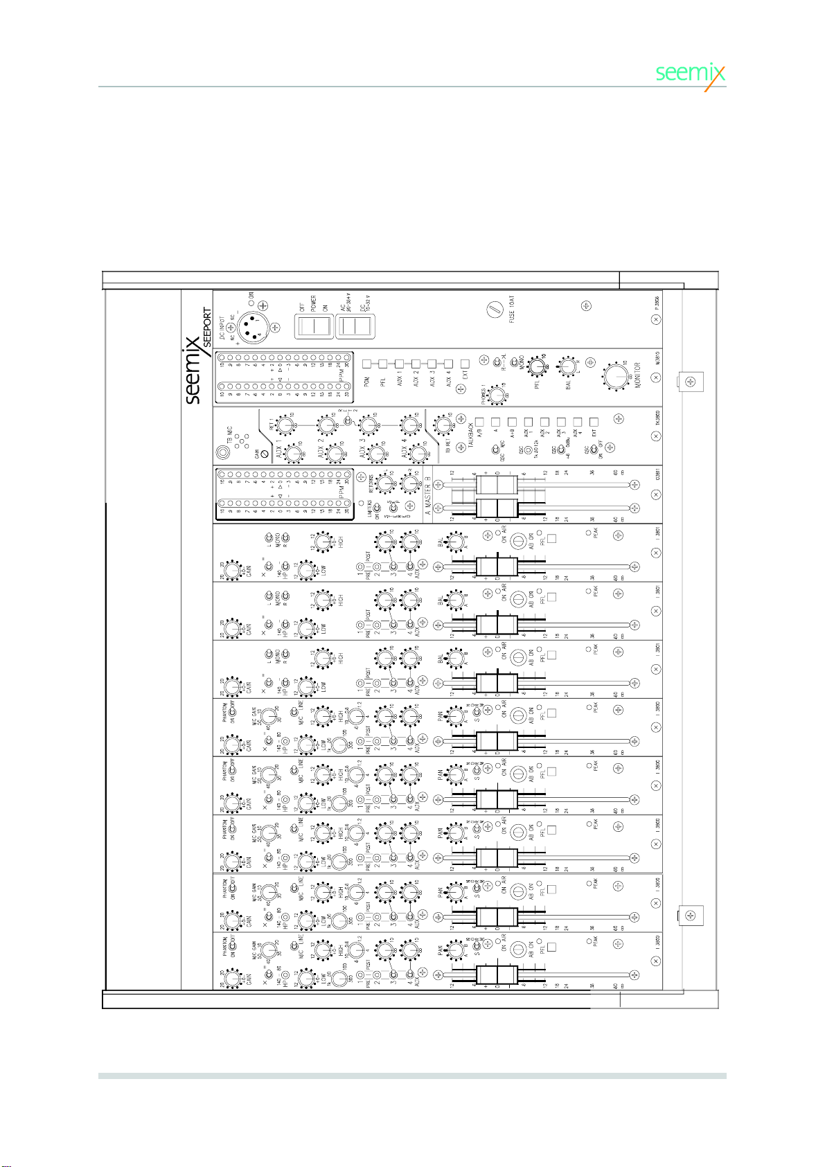
2. Mixer Layout
The following drawing is an example of an 8 channel configuration. Seeport
2
is available in
three frame sizes, housing 8, 12 or 16 input modules.
S
E
E
P
O
R
T

6© Seemix Sound AS
GAIN
+/-20 dB fine gain adjustment on mic and line inputs.
PHANTOM ON/OFF
Switch for selecting 48 V phantom power.
PHASE(X/=)
Phase reversal switch.
MIC GAIN
10-50 dB gain on mic input.
HP
High pass filter, 12 dB/octave. 80 Hz and 140 Hz cut off
frequencies.
MIC / LINE
Mic/Line input selector. (Separate XLR-type connectors).
LOW
Parametric equalizer low end. +/-12 dB, 50 Hz to 1kHz peak/
dip. Q=1.3 at max peak/dip.
HIGH
Parametric equalizer high end, +/-12 dB, 600 Hz to 10 kHz
peak/dip. Q=1.3 at max peak/dip.
AUX 1-4
Aux output pre/post selectors and level pots. AUX 1 and
AUX 2 have center off switches and no pots. Post fader may
be taken before or after AB ON switch (jumper selectable).
PAN POT
Pan pot for panning signal between A and B outputs when
A/B ON switch is depressed.
S/NORM SWITCH
With this switch in the S position, a phase reversal of the
signal is sent to output B. This provides therefore the ’S’ sig-
nal of an MS configuration on the AB outputs. The ’M’ signal
would be fed from a separate mic channel (in NORM posi-
tion). In this way, two faders can be used for controlling an
MS signal. Note: The pan pot must be set centred for both
channels when used in MS configuration.
ON AIR LED
This is lit when the fader is open and the AB Switch is ON.
AB ON
Channel On switch. Affects stereo output only, leaving AUX
and PFL active.
PFL
Pre-fade listen, with LED. Jumper settings determine
whether PFL is cut when channel is On Air, or is independent
of On Air status.
PEAK
Overload LED.
3.1 Mic/Mono Line Input Module, I3800
3. MODULES
7
Seeport
2
User Manual
SIGNALISATION.
When the fader is open, and AB-switch is on, the fader start relay for the
channel will be closed when the channel is in LINE position. In MIC
position, the CUE1 or CUE2 signalling bus may be fed (jumper
dependant).
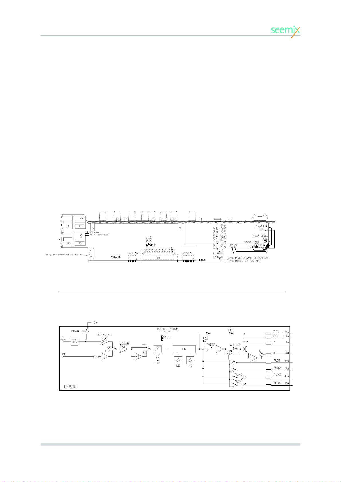
JUMPER SETTINGS.
The following jumper settings are available for the module.
• INSERT option
• CUE1 or CUE2 or no CUE when on air
• AUX POST dependent/independent of AB-switch
• PFL muted by ON AIR, or PFL independent of ON AIR
The positions of these jumpers are indicated in the diagram below.
3. MODULES
I3800 MODULE AUDIO BLOCK DIAGRAM
Module Information
Jumper settings
8© Seemix Sound AS
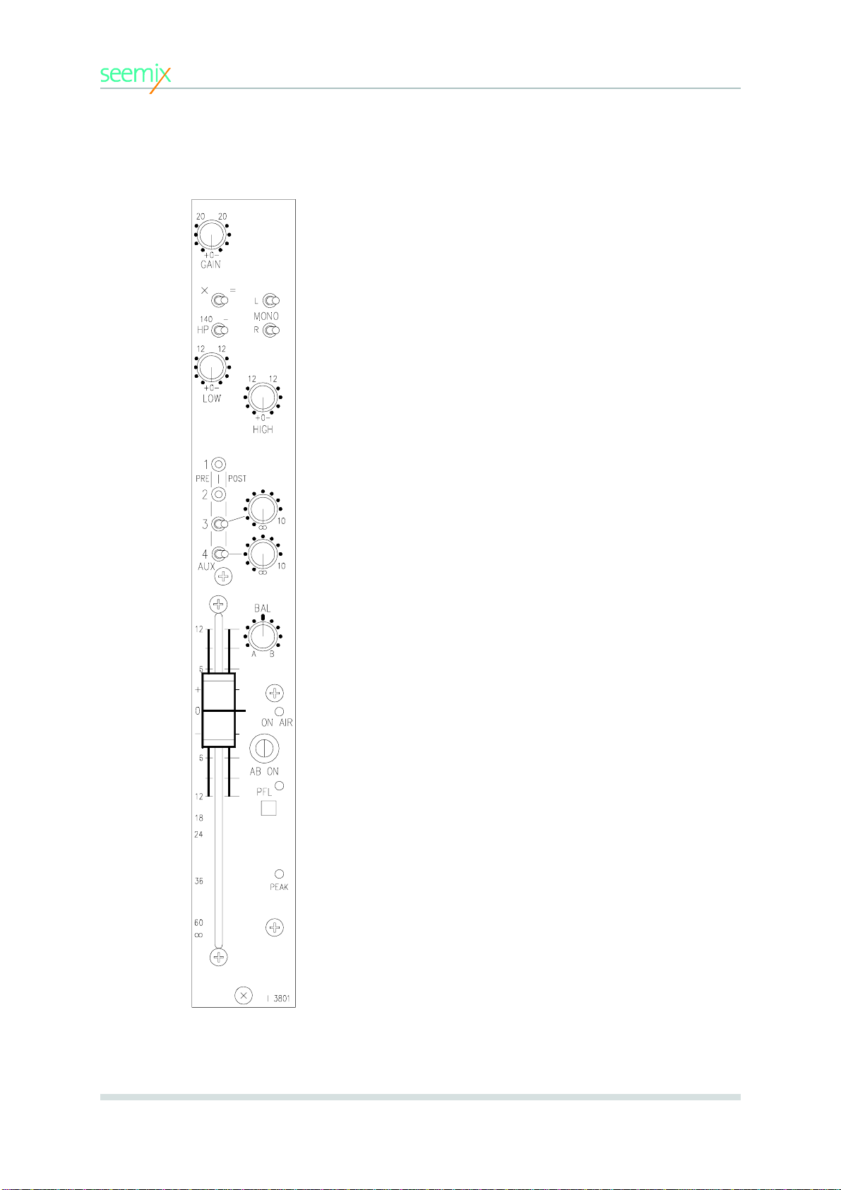
GAIN
+/-20 dB fine gain adjustment.
X/=
Phase reversal switch.
HIGH PASS
High pass filter, 12 dB/octave. Cut off frequency 140 Hz.
MONO L/R
When both switches are in the right position (as shown) the
channel is stereo. When the L position is used, the left input
signal is sent to both A and B channels. When the R position
is used the right input signal is sent to both A and B
channels. If both switches are used, both left and right inputs
are sent to both A and B channels.
LOW
Shelving filter low end, +/-12 dB.
HIGH
Shelving filter high end, +/-12 dB.
AUX 1-4
AUX output pre-post selectors and level pots. AUX 1 and
AUX 2 have center off switches and no pots.
AUX send signal is the sum of left and right channels. Post
fader may be taken before or after AB ON switch (jumper
selectable).
BAL
Stereo balance potentiometer. Adjusts balance between A
and B outputs when A/B ON switch is depressed.
ON AIR LED
This is lit when the fader is open and the AB Switch is ON.
AB ON
Channel On switch. Affects stereo output only, leaving AUX
and PFL active.
PFL
Stereo pre-fade listen, with LED. Jumper settings determine
whether PFL is cut when channel is On Air, or is independent
of On Air status.
PEAK
Overload LED.
3.2 Stereo Line Input Module, I3801
3. MODULES

9
Seeport
2
User Manual
Module Information
SIGNALISATION.
When the fader is open and AB-switch is on, the fader start relay for the
channel will be closed.
JUMPER SETTINGS.
The following jumper settings are available for the module.
• INSERT option
• AUX POST dependent/independent of AB-switch
• PFL muted by ON AIR or PFL independent of ON AIR
The positions of these jumpers are indicated in the diagram below.
Jumper settings
I3801 MODULE AUDIO BLOCK DIAGRAM
3. MODULES

10 © Seemix Sound AS
GAIN
+/-20 dB fine gain adjustment
EQ
Equalizer +/-12 dB, 150 Hz to 4,8 kHz peak/dip.
AUX 1-4
Aux output pre-post selectors and level pots. AUX 1/2 has a
center off switch and no pot. Post fader may
be taken before or after AB ON switch (jumper selectable).
SEND LEVEL
Level potentiometer for return signal to incoming caller. The
LEVEL LED indicates that the SEND level limiter is active.
SEND BUTTONS
Interlocking switches for selecting return signal to caller.
Caller may be sent any one of AUX1 or AUX2 signals
(jumper selectable), PFL, A+B (PGM) or an external signal
(EXT) connected at the back of the module.
”SET” OFF
”SET” OFF LED indicates that the telephone set is
disconnected. This is activated by the CONNECT button or
by CUE1 or CUE2 (jumper selectable). CUE1 or CUE2 may
be activated by any other channel when on air (eg. for red
light). This therefore avoids ringing interuption when for ex-
ample a local mic is live.
CONNECT
This button activates the hybrid function itself and connects
the line to the channel. It also disconnects the telephone
set (100ms after making the channel connection) as mentio-
ned above. Releasing the connect button breaks the con-
nection to the mixer channel and re-connects the telephone
set (again after 100ms) to enable off air conversation. NB:
The set will only be re-connected when the relevant CUE
signal is not present, e.g. local mic which controls red light is
off air.
CALL
The call LED gives a visual indication of the presence of an
incoming call. This is useful when ringing has been deacti-
vated by one of the cue busses when on air.
PAN
Pan potentiometer. Feeds main outputs if A/B ON switch is
depressed.
ON AIR LED
This is lit when the fader is open and the AB Switch is ON.
AB ON
Routes signal to A and B mix busses.
PFL
Pre-fade listen, with LED. Jumper settings determine
whether PFL is cut when channel is On Air, or is indepen-
dent of On Air status.
The drawing in the upper left corner of the module shows
the connections on the back panel.
3.3 Telephone Hybrid Module TH3800
3. MODULES

11
Seeport
2
User Manual
Module Information
TH3800 MODULE AUDIO BLOCK DIAGRAM
3. MODULES
The TH3800 can be used in several different ways, either as a straight hybrid (without interacting with the
rest of the mixer) or as an integrated mixer channel with routing to and from the mix busses.
The incoming line signal can be routed, via the AB ON switch, to the A and B master busses. It can also be
sent to the PFL bus as well as to all AUX busses either pre or post fade. However, the channel can only be
sent to either AUX1 or AUX2, not both. This choice is jumper selectable. The reason for this is that AUX1 or
AUX2 can also be selected as the return signal to the caller (SEND) (also jumper selectable). These jumpers
must therefore be set differently for the two signal paths in order to avoid a feedback loop. Further, if two
hybrid modules are used simultaneously, by setting these jumpers in ’mirrored’ positions for each module,
AUX1 and AUX2 can be used for cleanfeed mixes (N-1) for respectively line 1 and line 2.
The return signal (SEND) can be selected from AUX1/2 (as described above), PFL , A+B or an external
source. A+B would normally be selected when the line is to be used for transmission.
The module also has a channel out connector. This is fed from the post fade signal and provides an extra
output independent of the rest of the mixer. This enables the module to be used as a stand alone hybrid. For
example, the Channel Out is sent to an external mixer, and the output of this mixer is in turn connected to the
EXT input of the hybrid to provide the SEND signal to the caller. Any source connected to the EXT input can
be sent down the line for monitoring (SEND EXT). Similarly, any incoming telephone line signal can be moni-
tored directly from the channel output connector.
JUMPER SETTINGS.
The following jumper possibilities are available. Jumpers positions are indicated in the diagram below.
• CUE1 or CUE2 signals can mute ringing from telephone set to avoid interruptions when on air
• AUX POST dependent/independent of AB-switch
• PFL muted by ON AIR, or PFL independent of ON AIR
• STF (Norwegian standard), or 600 Ohm LINE IMPEDANCE
• LinemixedtoAUX1orAUX2
• AUX1 or AUX2 to SEND path (cleanfeed mix to caller)
Jumper settings

12 © Seemix Sound AS
STEREO PPM
Peak Programme Meter fitted with 16 LEDs.
Nordic scale: 0 dB on meter = 0 dBu output
LIMITERS
Selects stereo limiter in or out.
STEREO/SEP
Selects between stereo ganged limiters or separate for each
channel.
RETURN
Return level pots for A and B return inputs.
3.4 Output module, U3811
3. MODULES
AB
13
Seeport
2
User Manual
Module Information
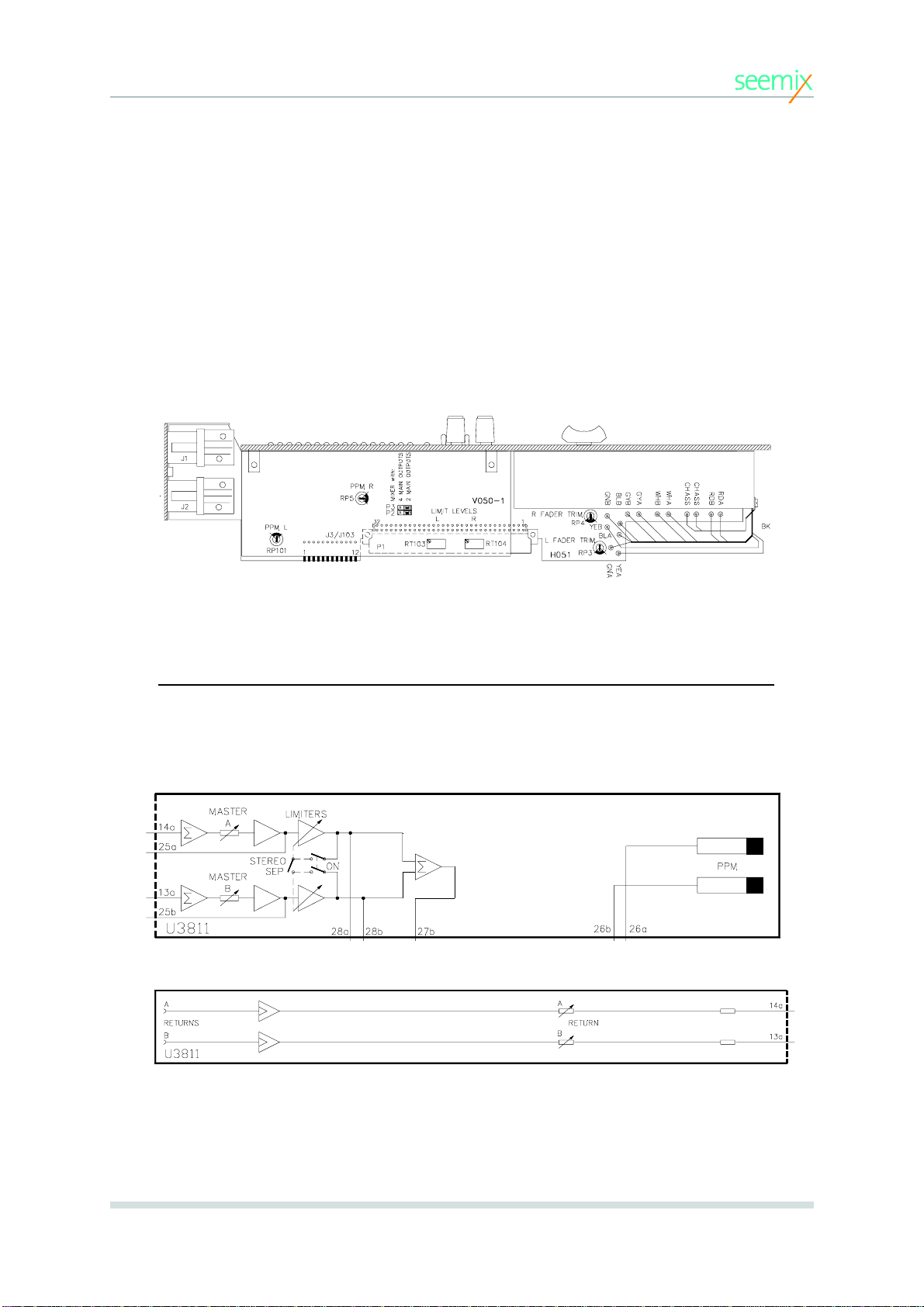
U3811 MODULE AUDIO BLOCK DIAGRAM
Jumper settings
SIGNALISATION.
When one or both faders are open, the fader start relay for the output
channels will be closed.
JUMPER SETTINGS.
This module is also used in the Seeport
4
mixer (two modules giving 4
outputs). Jumpers must be set accordingly as indicated in the drawing
below.
3. MODULES

14 © Seemix Sound AS
The U3804 is a stripped down version of the U3811 main
output module, for use where no controls are required. It has
no faders, limiters, PPMs or return inputs.
3.5 Light Output Module, U3804
3. MODULES
U3804 Module Audio Block Diagram

15
Seeport
2
User Manual
3. MODULES
THIS PAGE IS INTENTIONALLY LEFT BLANK

16 © Seemix Sound AS
STEREO PPM
Peak Programme Meter fitted with 16 LEDs.
Nordic scale: 0 dB on meter = 0 dBu output.
PGM
Sends stereo A/B sum to monitor output.
PFL
Sends stereo PFL sum to monitor output.
AUX 1 - AUX 4
Sends mono AUX1-AUX4 sums to both left and right moni-
tor outputs.
EXT
Sends signal from external stereo input (2 XLRs on back
panel), or from optional Y3802 module, to monitor output.
This routing is jumper selectable. See section 3.8 for infor-
mation on Y3802 module.
R
►
L
Sends right monitoring channel to both right and left moni-
toring outputs.
PHONES 1
Level control for the Phones 1 headphone output. The pho-
nes 1 output can be set to follow either the selected monito-
ring output, or always programme (jumper selectable). This
can be set individually for left and right outputs.
MONO
Sends mono sum of both monitoring channels to both out-
puts.
PFL
Potentiometer for adjusting level of PFL mono output.
BAL
Potentiometer for adjusting L/R balance of the stereo moni-
tor output.
MONITOR / PHONES 2
Level control for monitor/phones 2 output.
3.6 Monitor Module, M3810
3. MODULES

17
Seeport
2
User Manual
JUMPER SETTINGS.
The following jumper possibilities are available:
•Selection of external monitoring source from ext. input on back panel or
from optional Y3802 module (in 12 and 16 channel frameworks only).
•Phones 1 to follow monitor selection or always AB.
•Cue 1 signal can mute monitor/phones 2 output.
•Cue 1 signal can mute PFL output.
The positions of these jumpers are indicated in the diagram below.
Module Information
M3810 MODULE AUDIO BLOCK DIAGRAM
3. MODULES
Jumper settings

18 © Seemix Sound AS
TB MIC
An external talkback mic can be connected here. When in-
serted, the in-built talkback mic. is disconnected.
GAIN
TB mic amplifier gain adjustment.
AUX 1-4
AUX master output level potentiometers.
RET 1 AND RET 2
Potentiometers for adjusting Aux. Return levels. The RET1
mono signal may be mixed with each of the 4 Aux buses,
with separate level control for each bus. Alternatively, with
the switch in the RET2 position, the Aux 3 and 4 buses may
befedwiththeReturn2signal.
TB RET
Talkback return level potentiometer. The talkback return sig-
nal is sent to both L and R PFL buses.
TALKBACK BUTTONS
Non-latching talkback pushbuttons. Routes TB signal or
oscillator to respective output(s).
OSC / MIC
Talkback circuits can be fed either from the talkback mic or
from the built-in oscillator.
OSC 1k, 60, 12k
Oscillator frequency selector. 60Hz, 1kHz or 12kHz.
OSC +6, 0dBu
Oscillator level selector. 0 or +6dBu.
OSCONOFF
Switches oscillator on or off.
3.7 Talkback / AUX Master Module TK3800
3. MODULES

19
Seeport
2
User Manual
Module Information
OUTPUT AMPLIFIERS
Output amplifiers for auxiliary and main outputs are located on the
TK3800 module.
3. MODULES
TK3800 MODULE AUDIO BLOCK DIAGRAM

20 © Seemix Sound AS
PHONES (2)
Headphones jack connector. Headphones inserted here mo-
nitor the selected monitoring signal while muting the main
monitor outputs. The phones 2 output on the front of the
mixer is however not muted.
MON SOURCES TO EXT
Five external stereo sources, connected via a 25-pin D-sub
connector on back panel, can be summed and monitored
when the EXT monitor button on the M3810 module is selec-
ted.
COMPATIBILITY METER
Meter for indicating phase content/correlation in the stereo
output signal. Follows the selected monitoring source.
LOUDSPEAKER
Monitors the mono summed PFL signal.
3.8 Ext. Monitor, PFL & Phase Meter Module, Y3802
3. MODULES
Table of contents


