Seneca NUC Hospital Digital Network (HDN)
Installation & Service Instructions
Parts based on “SENECA NUC Media Player – Mounting & Installation” - V1 1 12/2016 by Eric Bram of Patient Point
Call (877)233-9114 for support
Author: Kirk Thomas
Page 6 of 20
Revision: 2c – Mount Integration
Last U date: 3/3/2017 12:01 PM
Premier 4263 Tilt Mo nt
Step 1 – Install the Wall Plate
Follow the manufacturer’s instructions for installing the wall late.
The wall plate m st be installed in two st ds. Fasteners are
included for both wood and metal studs.
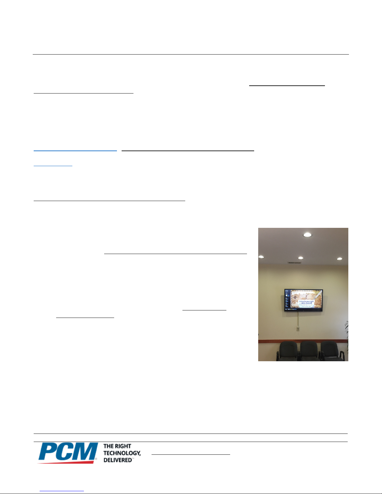
1.) Locate where yo are mo nting the monitor using the
ictures in the site survey. There should be a certain level
of clearance between the to edge of the screen and the
ceiling once it is mounted. Below are the minimum
clearances they must have once mounted:
•For 42” Monitor Installations: The to edge of the
monitor should be at least 11 inches from the ceiling.
•For 43” Monitor Installations: The to edge of the monitor should be at least 8 inches from the ceiling.
If the wall late is mounted above either of these measurements, the monitor will hit the ceiling which or reach
above the ceiling, making it hard to mount the monitor without removing the ceiling. (The permanent removal of
ceilings is a circumstance which tends to upset folks at the job site It is not recommended )
2.) Use an edge-to-edge st d finder to locate the edges of the studs. Draw a vertical line down the center of each
stud.
3.) Hold the wall late on the wall to use as a tem late over the two studs, already marked.
4.) Level the late and mark the center of the four mounting holes.
5.) Make sure that the mounting holes are on the stud centerlines
Step 2 – Mo nt Comp ter
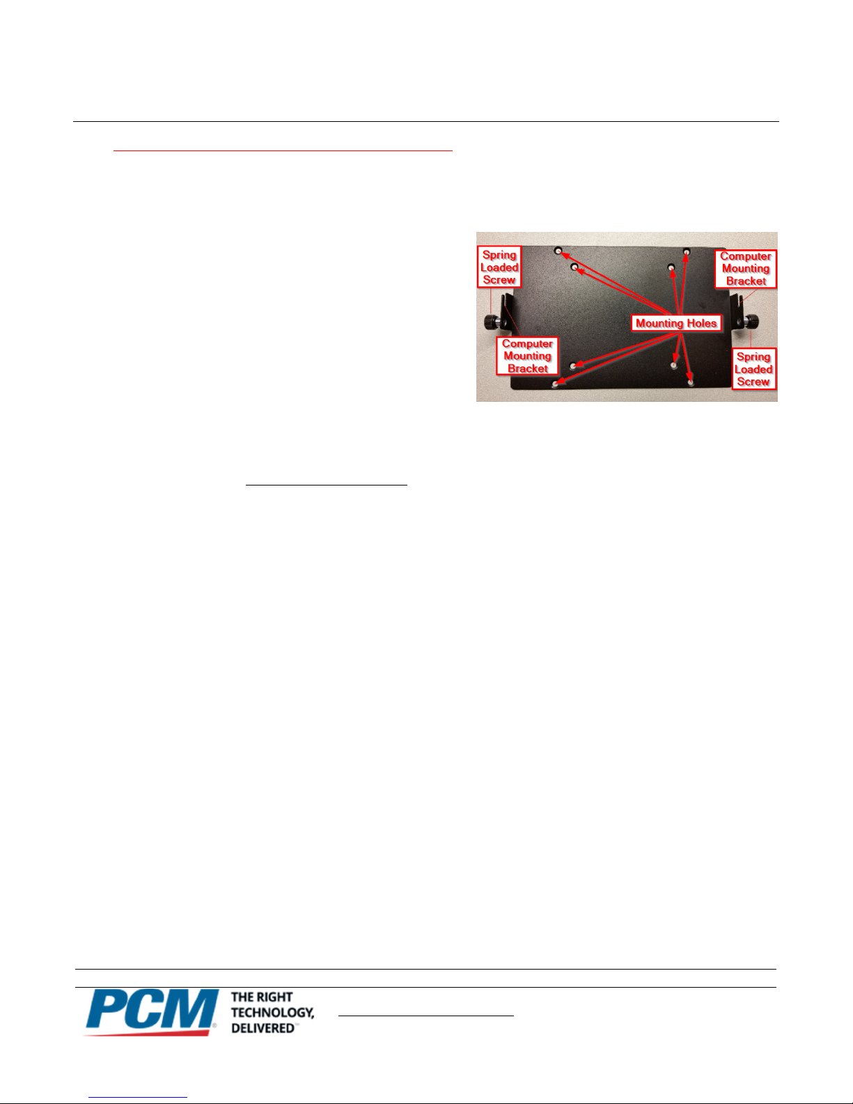
1.) The mounting bracket for the NUC layer should be installed
within the Premier P4263T mount’s wall bracket. (As shown )
2.) Make sure to mount the NUCs bracket so the media layer can
slide in face down into the bracket once it is installed. The
cable side of the media layer should be ointed u .
3.) Make sure the NUC is installed in a location that rovides
adequate clearance for the HDMI, RS-232, ethernet, and ower
connectors.
4.) Once the bracket is mounted, slide the NUC into the bracket
and tighten down the s ring loaded screws.
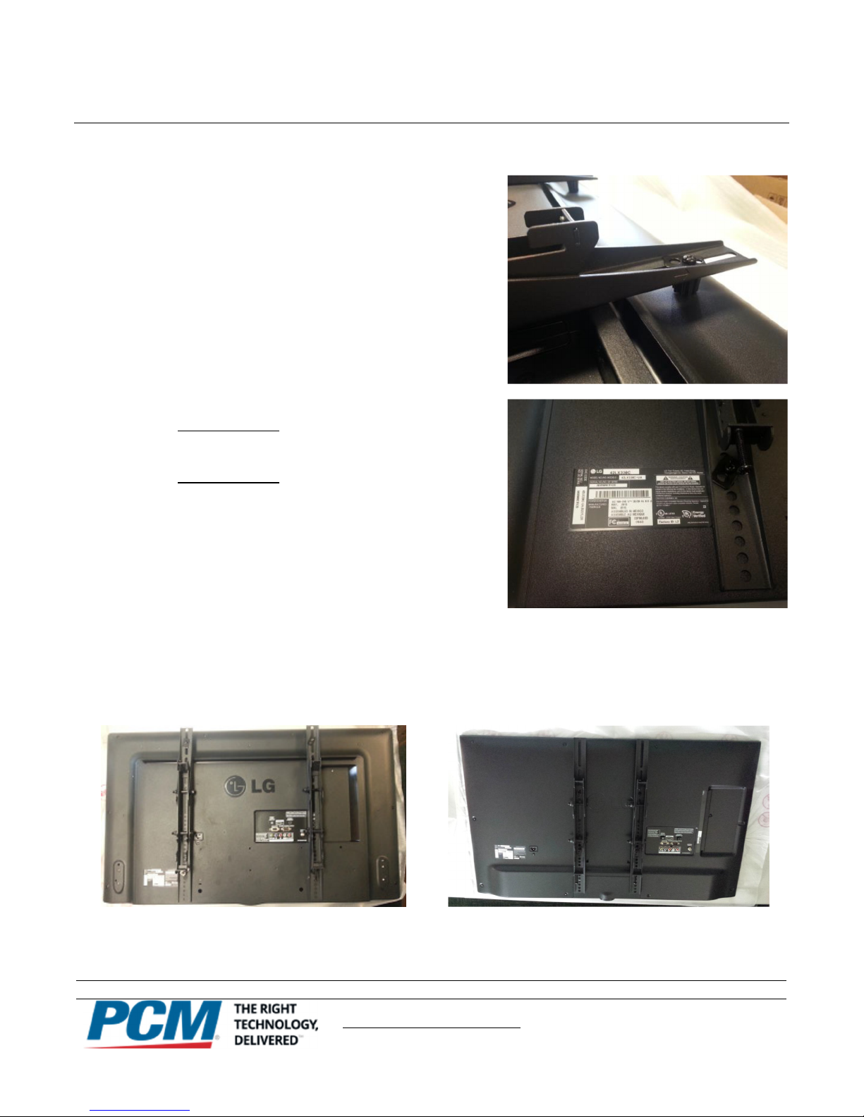
The Directional Mounting Arrow stamped into the top of
the wall plate indicates which edge is the top
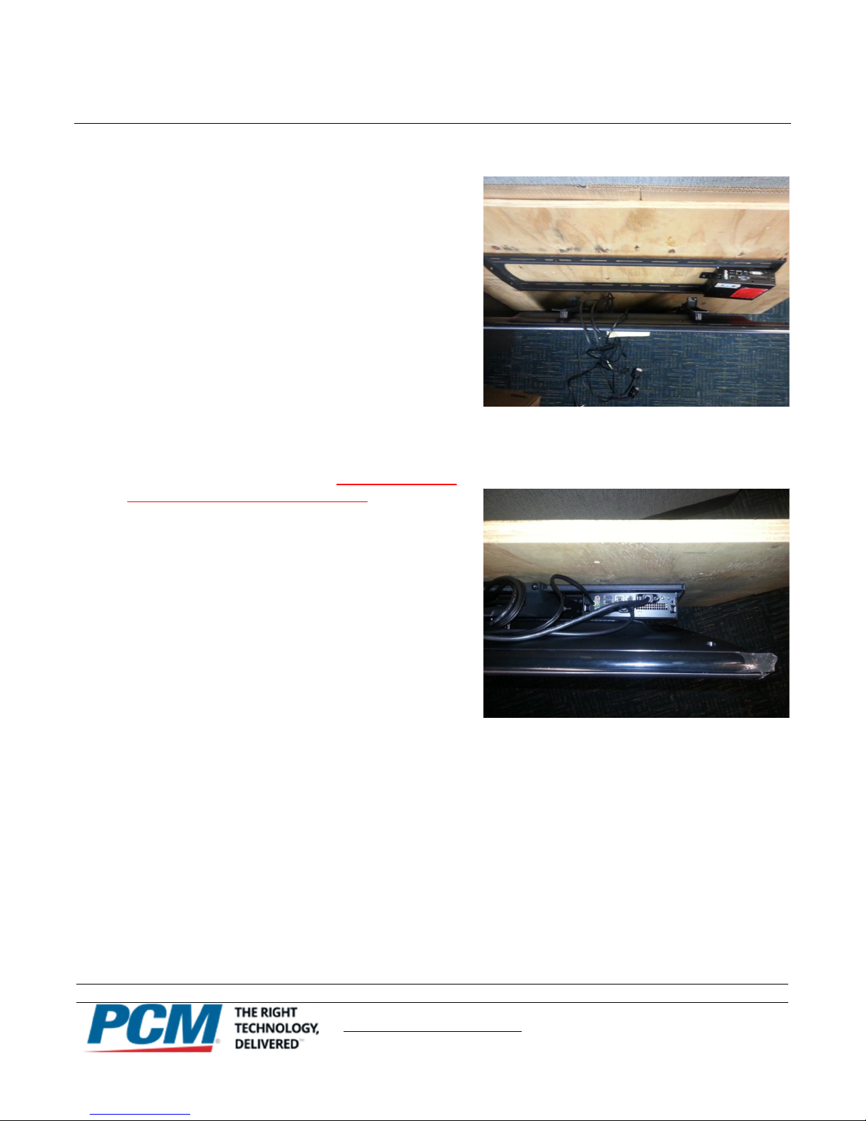
Seneca NUC installed within the Premier P4263T wall
bracket An electric power strip is draped on top of it
until the monitor can be mounted Then the power
strip will be put in its more permanent placement