Seodu InChip SDC-1000 User manual

Seodu InChip, Inc. Digital Media Div Draft, Manual
Page 1of 24
SDC-1000
Operation Manual
Seodu InChip, Inc.
Digital Media Division

Seodu InChip, Inc. Digital Media Div Draft, Manual
Page 2of 24
Index
1) Product Description
2) Outside View
lFront Panel
lRear Panel
lRemocon
3) Installation & Connection
4) Operation
5) Product Specification

Seodu InChip, Inc. Digital Media Div Draft, Manual
Page 3of 24
(1) Product Description
SDC-1000, Dolby Digital Pre-Amplifier from Seodu InChip, Inc. is designed to
support today’s leading-edge digital audio format, Dolby Digital (also known as AC3)
and Dolby Pro Logic along with digital PCM and analog audio from PC sound cards,
creating unrivaled 3D sound effect by using maximum of 6 speakers. End-users will
be benefited from ultimate multimedia sound effects at very low cost, when he/she
watches DVD movie, play 3D games and listening music. Fully utilizing embedded
high performance audio DSP and 20 Bit ADC/DAC supporting 48 kHz sampling rate,
it will allows PC users to feel and get full satisfaction which they might have gotten
from expensive consumer audio.
To watch and experience thrilling DVD movies using PC, you must have DVD-
ROM drive in your PC system and install a well-known S/W DVD player, such as
PowerDVD, WinDVD or Cinemaster DVD, which supports S/PDIF Digital output in
sound cards like SB! Live from Creative Labs. And install SDC-1000 Dolby Digital Pre-
Amplifier and appropriate powered speaker kits or audio amplifier, then you can enjoy
ultimate DVD movie and sound coming out of maximum 6 speakers in your small
world without expensive DVD player.
To play games in 6 channel sound, install the sound card which supports
Aureal 3D API version 3.0 in your system, connect its digital output to SDC-1000
system and speaker kits, and execute 3D games supported by Aureal 3D ver 3.0 API.
Then you can play fantastic 3D games in multi-channel sound.
To listen and enjoy very high quality audio, connect the digital output of
sound card to digital input of SDC-1000 and play audio applications like WinAMP,
Windows Media Player. Then you will hear very high quality, low noise digital audio by
bypassing noisy analog output path of sound cards. Also when you enable various
surround effects which are usually available in high-end consumer audio, you will get
exotic and nice feeling when listening music.
Allowing 4 CH analog input from modern sound cards from Creative, Yamaha,
etc, SDC-1000 has no problem in fully supporting them. Even if sound card in the PC
system has analog output only, end-user can still use surround modes and get multi-
channel sound effects from just 2 channel analog input.
And also thanks to easy speaker mode setting, automatic speaker detection
and bass management, end-users do not need all 6 speakers from the beginning.
Simply start with 2 speaker system and later add and/or upgrade additional speaker
sets. It’s very easy way to use the system and also economical. There is no need to
discard your existing speaker systems when you use SDC-1000.
Lastly but not least, without sacrifice in performance and feature compared to
consumer audio products, you may use the SDC-1000 system in anywhere you want
to, other than PC environment.
* Dolby Digital, Dolby Pro Logic,Dolby Surround, Double-Dsymbol and AC-3are
the registered trademarks of Dolby Laboratories Inc.

Seodu InChip, Inc. Digital Media Div Draft, Manual
Page 4of 24
(2) Outside View
lFront Panel
-Buttons and Knob (Buttons in Remocon)
(A) POWER Button (Power in Remocon Panel)
Standby Power On/Off Switch of SDC-1000
(B) INPUT Button (Input in Remocon Panel)
With every touching, inputs following will be selected
Digital Optical : Select Optical Digital Input in rear panel
Digital Coaxial : Select Coaxial Digital Input in rear panel
Analog Line In : Select LINE-IN (2 CH/4 CH) Analog Input in rear
panel
(C) SURROUND Button (Surround in Remocon Panel)
With every touching the button, surround audio modes following will be
selected
Bypass : Select “Bypass”mode (all surround LEDs off) which is
without effect and modification to audio input
2
Surround : Select Dolby Surround (Pro Logic)
Dolby Digital stream will be automatically detected, decoded
and played
Stereo : Select 2 speaker (Left/Right) only mode
Music : Select “Music”Surround mode to give better sound field
effect using multiple speakers with normal stereo input.
Suitable for listening music
Theater : Select “Theater”Surround mode to give better sound field
effect using multiple speakers with normal stereo input
Suitable for listening music and playing game
Stadium : Select “Stadium”Surround mode to give better sound field
effect using multiple speakers with normal stereo input
More intensive sound effect than “Theater”mode and
suitable for playing game
Note :Music/Theater/Stadium surround modes will not be enabled
when playing Dolby Digital
Note :2Surround and Stereo modes will only be selected when playing
Dolby Digital stream.
(D) FUNCTION Button (Function in Remocon Panel)
With every touching the button and adjusting Volume Knob (s,t Buttons
in Remocon Panel), audio function modes following will be selected
S Delay : Adjust surround delay in Dolby Digital and Pro Logic mode
C Delay : Adjust center delay in Dolby Digital and Pro Logic mode
D.R.C : Adjust dynamic range compression ratio in Dolby Digital
mode
Note :Functions above are applicable when playing PCM or Dolby Digital,
Dolby Pro Logic mode. So if you have selected surround mode like
Music, Theater or Stadium, these functions will not be enabled

Seodu InChip, Inc. Digital Media Div Draft, Manual
Page 5of 24
(E) VOLUME Knob (TRIM Adjustment) (Volume,s ,tin Remocon Panel)
Master volume setting will be modified when rotating Volume Knob.
To adjust individual minute speaker level, push the Volume Knob, then
with every touching, trim control modes following will be enabled
Right : Trim Front Right speaker level by +10dB to -10 dB
Left : Trim Front Left speaker level by +10dB to -10 dB
Center : Trim Center speaker level by +10dB to –10 dB
Rear Right : Trim Rear Right speaker level by +10dB to –10 dB
Rear Left : Trim Rear Left speaker level by +10dB to –10 dB
S. Woofer : Trim Sub Woofer speaker level by +10dB to –10 dB
(F) TEST TONE Button (Test Tone in Remocon Panel)
When INPUT and FUNCTION buttons are pressed simultaneously, system
will enter Test Tone mode, in which test signal will be generated and
sequenced through the order of Front Left –Center –Front Right –
Rear Right –Rear Left –Sub Woofer speakers in every 2 seconds,
skipping non-existing speakers. So user can correct speaker position and
its level during testing by adjusting volume knob. (s,t Buttons in
Remocon Panel) Pressing any button again will make system come back
to normal playback mode.
(G) MUTE Button (Mute in Remocon Panel)
When pressing MUTE button, signal output to Line Out will be muted.
-LED Indicators
(A) SURROUND LEDs
Bypass (no LED) -2Surround –Stereo–Music –Theater –Stadium
When pressing SURROUND button, LED will be turned on to the order
above.
And if Dolby Digital stream is detected in the digital input, 2Surround
and 2Digital LEDs will be turned on, automatically.
(B) INPUT LEDs
Dig. In –Ana. In
When pressing INPUT button, LED will be turned on, indicating if analog
or digital input is selected.
And also character display will show current input port
d:OP for optical digital input
d:CO for coaxial digital input
A:In for analog input
(C) Master VOLUME
Adjusting Volume Knob (s,t Buttons in Remocon Panel) will display
current master volume level.

Seodu InChip, Inc. Digital Media Div Draft, Manual
Page 6of 24
(D) TRIM Control
When pressing VOLUME button, character display will show selected trim
adjust and its setting in the order below
F-r for front right trim control
F-L for front left trim control
Cfor center trim control
r-r for rear right trim control
r-L for rear left trim control
S-U for sub woofer trim control
(E) FUNCTION
When pressing FUNCTION button, character display will show selected
audio function and its setting in the order below
C-d for center delay adjustment
S-d for surround delay adjustment
drc for dynamic range compression adjustment
(F) 2Digital
Turned on automatically when Dolby Digital stream is detected
(G) 2Pro Logic
Turned on when user selects Dolby Surround (Pro Logic) mode, or also
turned on automatically when Pro Logic encoded Dolby Digital stream is
detected in digital input
(H) PCM
Turned on when input signal is PCM digital input or Analog input
(I) Test Tone
Turned on when system is in Test Tone mode
(J) Error Music
Turned on when error (like disconnection) is detected in incoming digital
stream
(K) Input High
Turned on when analog input signal level is too high, so producing
clipping. In that case, turn down analog input level.
(L) CHARACTER DISPLAY
Displays useful information on current status, setting and input mode.
Normally it will show current input selection, i.e.
d:OP in optical digital input mode
d:CO in coaxial digital input mode
A:In in analog line in mode

Seodu InChip, Inc. Digital Media Div Draft, Manual
Page 7of 24
When Dolby Digital stream is coming in, it will show incoming Dolby
Digital audio format, like
3:2.L when incoming data is 5.1 channel encoded 2Digital signal
2:0 when incoming data is L/R encoded 2Digital signal
When you adjust volume knob in Volume or Function mode, it will show
current setting accordingly, like
-32 when master volume level is –32 dB
When you are performing speaker test, it will show current speaker
positioning in test, like
F-l when performing front left speaker test
C when performing center speaker test
F-r when performing front right speaker test
r-r when performing rear right speaker test
r-l when performing rear left speaker test

Seodu InChip, Inc. Digital Media Div Draft, Manual
Page 8of 24
lRear Panel
-DC Adapter Input
Input connector for AC-to-DC 12V adapter power supply
-Variable Line Outputs
(A) Front L/R
Left/Right stereo output connector to external power amplifier or
multimedia PC speaker (with power amp) for front Left/Right line out
Note :When connecting PC multimedia speaker with Sub-Woofer to this
connector, set “Front L/R Size”bit of Speaker Mode DIP SW to “1”
(B) Rear L/R
Rear Left/Right stereo output connector to external power amplifier or
multimedia PC speaker (with power amp) for rear Left/Right line out
(C) Center
Center mono output connector to external power amplifier or
multimedia PC speaker (with power amp) for Center line out
(D) S. Woofer
Sub Woofer mono output connector to external sub woofer amplifier
-Inputs
(A) Digital Optical
Optical S/PDIF digital input from PC Sound Card or other digital audio
equipment like DVD player
(B) Digital Coaxial
Coaxial-RCA S/PDIF digital input from PC Sound Card or other digital
audio equipment like DVD player
(C) Line-In
2 CH or 4 CH audio input from PC Sound Card or other audio
equipment like portable CD player

Seodu InChip, Inc. Digital Media Div Draft, Manual
Page 9of 24
-DIP Switch (Speaker Mode)
DIP switch for selecting speaker type and existence
Bit # Definition Up (1) Down (0)
1Rear Speaker Installed Not available
2Front L/R Speaker Size Full-Range
Front L/R speaker Satellite
Front L/R speaker
Note :“Full-Range”speaker is the speaker capable of producing wide
frequency signal range of 20 Hz to 20 kHz
Note :“Satellite”speaker is the small speaker without capability of
producing signal of 20 Hz to 120 Hz in low frequency range
Note :“Installed”Rear speaker means that poweramplifier with speaker is
connected to the Rear L/R Line Out connectors
Note :Existence of Center and Sub-Woofer speakers will be automatically
detected.

Seodu InChip, Inc. Digital Media Div Draft, Manual
Page 10 of 24
lRemocon
-Power Button
Power on/off
-Mute Button
Sound output muting function
-Input Button
Input selection
-Surround Button
Surround mode selection
-Function Button
Dolby function selection
-Volume Button
Volume selection
-Up ( s ) Button
Volume/Function value up
-Down ( t ) Button
Volume/Function value down
-Test Tone Button
Speaker test start
Mute
Volum
e
Input
Surround
Function
Test Tone

Seodu InChip, Inc. Digital Media Div Draft, Manual
Page 11 of 24
(3) Installation & Connection
-Placement and Power Connect
Place the system on your desk or any other place for easy access and
connect AC-DC 12V adapter
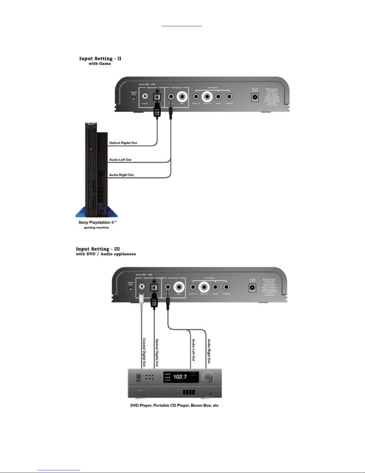
-Input Connection
(A) Connect the Line out of PC Sound Card to the Line In connectors of
SDC-1000
-If PC Sound Card has 2 CH stereo output only, then connect to the
front Line-In of SDC-1000
-If PC Sound Card has 4 CH output, then
Connect front Line output of sound card to front Line In of
SDC-1000
Connect rear Line output of sound card to rear Line In of
SDC-1000
(B) If your PC Sound Card has S/PDIF Digital output, then connect them
to Digital input of SDC-1000 depending on the type of connector
(Optical or Coaxial-RCA)
(C) Since SDC-1000 has two digital inputs, you may connect other digital
signal source from Laser Disc Player, DVD Player to remaining digital
input port of SDC-1000
(D) Please refer the following pages for typical input connections of SDC-
1000. But those are not all. You may find various applications for
SDC-1000 by your own.
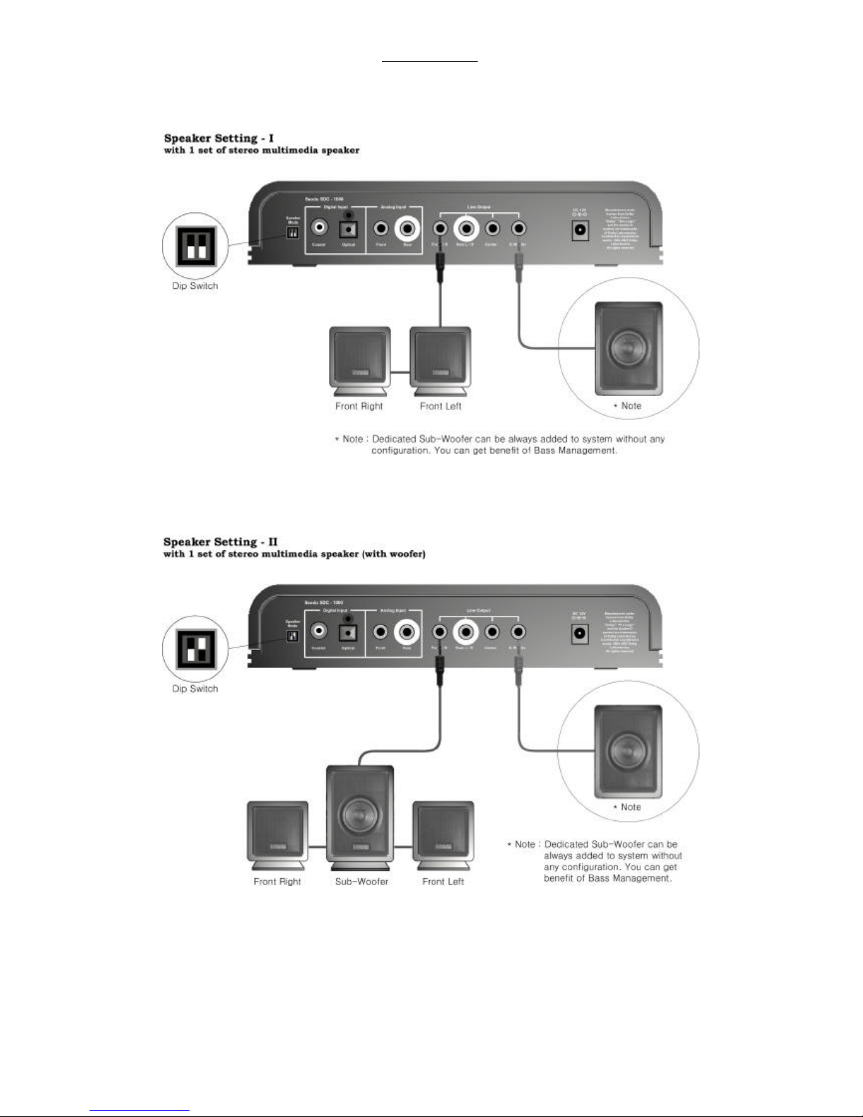
-Output Connection and Speaker Mode Setting
(A) Based on availability of multimedia PC speakers and power amplifiers,
connect them to the proper line output of SDC-1000 and set/reset
“Speaker Mode DIP Switch”bits according to front speaker size and
existence of rear speakers.
(B) Existence of center and sub-woofer is automatically detected. So, if
you have good sub-woofer amplifier, simply connect it to the Sub
Woofer Line Out connector of SDC-1000. No additional configuration
is needed.
(C) Please refer the following pages for typical speaker connections and
DIP switch settings of SDC-1000. Also, those are not all. You may also
find another applications for SDC-1000 by your own.
-Speaker Test
After Power On, pressing INPUT and FUNCTION button in front panel
simultaneously, or Test Tone in Remocon Panel, initiate speaker test
mode, and verify correct speaker positioning and also adjust individual
volume level if necessary.
When everything done, press any button and return to normal
operation mode.

Seodu InChip, Inc. Digital Media Div Draft, Manual
Page 12 of 24
Seodu InChip, Inc. Digital Media Div Draft, Manual
Page 13 of 24
Seodu InChip, Inc. Digital Media Div Draft, Manual
Page 14 of 24

Seodu InChip, Inc. Digital Media Div Draft, Manual
Page 15 of 24

Seodu InChip, Inc. Digital Media Div Draft, Manual
Page 16 of 24

Seodu InChip, Inc. Digital Media Div Draft, Manual
Page 17 of 24

Seodu InChip, Inc. Digital Media Div Draft, Manual
Page 18 of 24

Seodu InChip, Inc. Digital Media Div Draft, Manual
Page 19 of 24

Seodu InChip, Inc. Digital Media Div Draft, Manual
Page 20 of 24
Table of contents


