Shadow-Caster SCR Series User manual
MODEL #s: SCR-16-AG-BZ-10 •SCR-16-BB-BZ-10 •SCR-16-BW-BZ-10 •SCR-16-CR-BZ-10 •SCR-16-GW-BZ-10 •SCR-16-UB-BZ-10
SCR-24-AG-BZ-10 •SCR-24-BB-BZ-10 •SCR-24-BW-BZ-10 •SCR-24-CC-BZ-10 •SCR-24-GW-BZ-10
INSTALLATION INSTRUCTIONS
SCR SERIES
WHAT YOU WILL NEED:
qScissors
qLow stick masking tape
qPower drill with 3/4” (19mm) and 9/64” (3.5mm) drill bit
Shadow-Caster™LED Lighting | 2060 Calumet Street | Clearwater, FL 33765
p: +1 727.474.2877 e: info@shadow-caster.com w: shadow-caster.com
Designed & Manufactured
in Clearwater, FL
© 2023 Shadow-Caster™LEDs. All Right Reserved. 2023/2
Shadow-Caster™Marine LEDs utilize state-of-the-art high powered LED technology combined with a rugged military grade design to bring you the
best value in underwater lighting. Our lights are manufactured in the U.S.A. and are inspected to meet the highest standards of quality.
Please read the following instructions completely before installation:
1. Choose mounting location - The lights require water cooling and should be installed on a flat surface area that is below the water
line. Also consider the area inside the boat where the wire will enter and make sure it will be accessible to retrieve the wire. It is NOT
recommended to mount the lights on hull running surfaces.
2. The template below can be used for nding an appropriate mounting location. Verify that the template matches the mounting holes on
the light if using this as a drill template. Make sure you are drilling into a place where you can get to the hole from inside the boat in order
to feed wire. Mark center drill location with pencil.
3. Drill a 3/4” diameter hole for the cable in the center hole location only (shown on template).
4. If mounting to an aluminum hull you will need to purchase part number: “SCM-GASKET-SCR” for galvanic isolation to prevent corrosion.
5. Feed the cable through the hull into the boat.
6. With the light against the hull in the location to be mounted, use the actual mounting holes of the light to mark one mounting hole. Drill that hole with
an appropriately sized drill (9/64 is typical for #8 screws). Be sure the drill is not over sized or undersized. An undersized hole can cause the screws to
break, oversize the hole and the hole will strip. With the light in place thread a screw into the hole. Now mark and drill the last mounting hole.
7. This procedure will prevent damage to the rubber boot where the cable comes out of the light. Gross misalignment of the mounting
screw holes can cause excessive side loads on the boot. Now check the mounting hole alignment with the light against the hull in the
mounting location. If the mounting holes are not both easily visible through the holes in the light, then the center hole for the cable must
be reamed until the light can be aligned with the mounting holes.
8. Place a sufcient amount of marine sealant on the hull around all holes to seal them against the light’s base plate.
9. Fill the screw holes with sealant.
10. Use provided screws to mount light to the hull. If alternate screws are used they must be silicon bronze. After mounting wipe off any
excess marine sealant around the light. Gently remove any spots with denatured alcohol on a lint free rag or cloth. Using cleaners that
contain solvents other than alcohol may damage light and potentially void warranty. This includes acetone, acetates, ethers, esters
acetates, xylene, amines, hydrocarbons, methyl ethyl keytone (MEK).
11. Install wiring:
a. Route wire through the boat in a manor such that it is tied up out of standing water and protected from excessive heat or abrasion.
b. Route wire to a switch or power distribution system.
c. Red wire is positive, black wire is ground. The lights must be wired through a fuse or circuit breaker. Failure to do so could
cause a re and injury or death. Each light should be fused separately and will require 8 amps at 12 volts, with a 10 amp fuse to
handle in-rush current for SCR-24, 7.5 amp fuses for SCR-16s.
d. Green control wire: Is optional, and can be connected to a momentary to ground switch to access fade and strobe modes.
Green wire is not used when utilizing Shadow-NET™ control.
e. Orange and yellow wires are for optional Shadow-NET™ controller. See the Control Systems section of our website for more information.
SCR-16 • SCR-24
qAlcohol based cleaners and/or mild soap & water
qClean cloth or paper towel
qMarine sealant, Sikaflex®-291
PLEASE READ INSTRUCTION INSIDE TEMPLATE
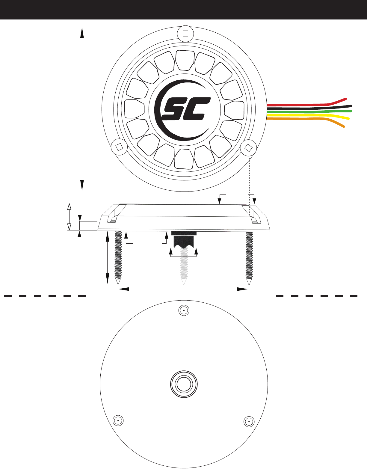
HEIGHT
4” [101mm]
.6” [16mm]
.2” [5mm]
1 1/2” (#8)
Silicon Bronze
24 Gauge
Tinned Wire 1 1/2” [38mm]
Silicone Bronze
Flat Head Screw
Robertson Drive #2
SIDE VIEW
.75” [17mm]
3” [77mm]
TAPE
HERE
DO NOT USE TEMPLATE
TO MARK SCREW HOLES
TAPE
HERE
DO NOT USE TEMPLATE
TO MARK SCREW HOLES
TAPE
HERE
TAPE
HERE
FOR CENTER WIRE HOLE USE
THE FOLLOWING:
1. Drill pilot hole at center for the wire, then
use 3/4” drill all the way through
2. Run wire through the hole and mark one
mounting hole location
3. Follow steps on front of sheet for drilling
mounting holes
WHEN PRE-DRILLING SCREWS:
First pre-drill center hole and run
wire. Then mark your screw holes
with drill bit or pencil while using
actual light housing
WHEN PRE-DRILLING SCREWS:
First pre-drill center hole and run
wire. Then mark your screw holes
with drill bit or pencil while using
actual light housing
TOP VIEW
Bottom
Base Plate
INSTALLATION DIAGRAM FOR: SCR-16 • SCR-24
WIRE COLOR CODE BREAKDOWN:
RED: +12V 8amps for SCR-24
5 amps for SCR-16
BLACK: Ground
GREEN: Optional “Mode” Control
YELLOW: Shadow-NET™ +
ORANGE: Shadow-NET™ -
This manual suits for next models
11


