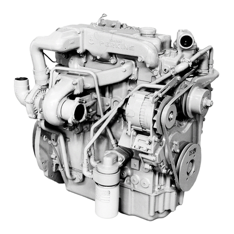
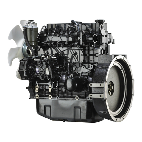
Shandong HUAFENGDONGLI 4102 Series User manual

HUAFENGDONGLI
4102
Series
Diesel
Engine
Operation
And
Maintenance
Manual
Shandong Weichai Huafeng Power Co.,Ltd

Preface
HUAFENGDONGU brand 4102 series diesel engine is afour -stroke, water -cooled,
inline
and
direct injecting combustion chamber
type,
high -speed diesel engine. 4102
series
is bore -enlarged
from
95
series.
In
1980s our company adopted the comet Vcombustion
system and diesel design technique
of
Ricardo Consulting Engineers Company and have made
great improvement
in
design. This type diesel engine possesses perfonnances of high power,
economy
and
liability, and reaching aadvanced level among the same kinds products all over
the world.
The National Science Congress prized HUAFENGDONGU brand 4102 series diesel en-
gine and it is easy to adapt. According to the different application, through being changed for
some
of
its parts accordingly,
it
can
be
l1sed
to match with middle tractors, engineering
ma-
chinery, middle vehicles, generating
sets,
irrigating machinery and agricultural machinery
and
so
00.
4102 series is developed from 495 series, main
parts
are
reinforced, Electrical
system, Inlet system, Exhaust system, Cooling system have improved, and the output range
is enlarged. ZH4102 is developed from K4102. It adopts the direct injecting combustion
chamber,
and improved its economy further.
The
model, its make -up role
and
the meaning
of the symbol for every type is as follows:
ZH
K
(J)
4
4
@
102
102
®
o
o
@
o
o
@
0--0
0--0
~
00
00:
Distinguish symbol, Expressed with number sequence
~:
Version symbol, expressed with number sequence
@:
Application feature symbol, expressed with alphabet
No
alphabet: for conunon
use;
T:
for tractor;
G:
for engineering machinery; Q: for vehi-
cle;
D:
for generating
set;
C:
for marine
use;
P:
for power take -off
unit;
Y:
for trans-
porting vehicle use.
@:
Con3truction feature symbol, expressed with alphabet; no alphabet: for
natural
aspirated
model;
Z:
for turbocharged model.
@:Cylinder
bore
(mm)
@:
Cylinder
number
(J): Cylinder expanded
(ZH:
Direct injecting combustion chamber)
period maximally, reduce the cost
of
usage, we compiled this manual on the basis of the "
Nation Rated 495 Diesel Engine Manual"
and
the ch8nge and improvement
of
products to in-

troduce the operation and maintenance knowledge to the customers.
This operation manual mainly introduces common usage type. For the products is chan-
ging and improving continually tthere may
be
some slight difference between
the
products
and
that described in this manual
and
the users are advised to notice it
kindly.
The manual is complied
by
Yu Caihong, Wei Yunfeng, Zhao
Ruian,
Wang Jinghai, and
Sun Chuanhai. Advised
by
Li
Peiyan, Chen
ling,
and
finally examined
and
approved by
Li
~
Huaiq(ng.
For the limit of the compilers, there may
be
some mistakes in the
manual,
if
you find
any,
please point out so that we can be corrected.
The
compiler
November
2005

Attention
1.
The diesel engine operators must familiarize themselves
with
this manual as well as engine
comstruction and strictly'follow the procedures
of
operation and maintenance especially the
regulations for safety opera -lion described in this manual.
2.
Before operating an engine
at
full load,the
60
hours
mnning in should
be
carried out as
specified in the manual.'
3.
Increase its speed gradually after stating acold engine, never let it ron
at
highs speed ab-
ruptly, and dontstop the engine instantly while its cooling water is still hot,also donflet
the engine running long time without load.
4.
IT
the ambient temperature falls below +
S'C
,drain
the cooling water out
of
the radiator,
the lubricating oil cooler and
the
diesel engine itself completely after stopping the engine.
Con -tinuous keeping the water in the oil cooler should
be
forbid -den.
5.
Never run the diesel engine without and air cleaner so as to prevent the unfiltered air from
entering the cylinders.
6. The engine must
be
filled with specified grade fuel and lubri -cating
oil,
and aspecial and
clean container for each oil should be used. The fuel oil should
be
settled for
72
hours and
fil -tered before using.
7. The inspection and repair of the components in electrical sys -tern must
be
carried out by
the person who 'has a
good
knowledge of electricity.
8.
The working environment of the diesel engine should
he
well ventilated to avoid being pol-
luted by waste gas or smoke.
9.
The power rating
and
amending of the diesel engine is ac -cording to GB6072. 1 - 2000
the first section of reciprocating internal combustion engine: standard basic condition, the
rating and testing method of power, fuel consumption and engine oil consumption.
10.
The manufacturing of the diesel engine is according to the common technical requirement
for
low
and middle level powered diesel engine in JB/T889S
-1999
and Q/WHFOO2 -
2005 495 series diesel engine enterprise standard.
11. The
No.
of production license of this series diesel engine
is:XK06
-205
-OO524,XK06
-
205
-002790
12. The position
of
safety warning marks:
(1 ) Theresguard against burning mark at the end of the cylinder cover which is beside
the exhaust manifold of the diesel engine.
(2 )Theresaguard against fire mark
at
the oil filler.
( 3 ) Theresaguard against
twinning
mark
on
the
inlet
man
-ifold.

680
828.5
9-M12
depth
19
320
600
90
o
(".J
CO
OutlinG
.dra:wift.f;
for
1:111020
dioool
onlY-no
• 1 •

ge
g/kW
..
h
450
420
390
360
330
300
270
240
\
1\
\
~
\1500r/min
~
1\
'
~
~~
\
~
~
~
",
r\
\
1800r/min
\\vV
\\\
~
v
,V
~\
2000r/min
~
\ \
1\
.IV
\
~
\K
~
~
'\
"
~
~
~
""
'"
'"
"-
""'II
'"
~
~
r---.....
~
-............
--
r-----..
---
"""'--
r-----..
I'----
~
--
10
15
20
25
30
35
40
pe
kW
· 2 ·
Load
characteristic
curve
for
1500,
1800
,
~r/min
diesel engine

4102 Main Technical Specifications
NO
~
4102
K4102 K4102G K4102P
ZH4102D
1
Type
Four strokes, Water Cooling,
Inline,
Swirl
combustion chamber
2Cylinder
No.
-Bore *Stroke 4 -
-102
x115
(mm)
3Total Displacement of Piston
3.76
(L)
4Pressure Ratio
19:
1
5Firing Order
1-3-4-2
6Air Intake Mode Naturally Aspirated
Ih
Output I
Speed 44/2000 36.3/1500 46.6/2400 44/2000 36.3/1500
Rated
(kW/r/min)
7Working
Condition 12h Output I
Speed 4012000
33/1500
40/2000
33/1500
(
kW/r/min)
8Highest Idling Speed
~2160
~1575
~2640
~2160
~1575
(r/miD)
9Lowest Idling Stable Speed
~550
(
r/min)
10 Max
Torque/Speed
219/1500
213/1680 219/1500
(N.
mlr/min)
11
Average
Effective
650
702
620
650
702
I---
Pressure(Kpa)
12
Fuel
Rated Consumption Rate
~258.4
~266.6
~258.4
I---
Working
(glkW.
h)
13
Condition Oil Consumption
-Rate{
glkW.
h)
~2.04
14 Exhaust
temperature(
CC
)
=::;;600
15 Crankshaft Rotating Direction
Anti
-clockwise
(Facing
to the power output
end)
16 Cooling Mode Forced Water Cooling
17 Lubricating Mode Compound type with pressure
and
splash
18
Startin2
Mode
Electric
startin2
19
Net
Mass{
kg)
320 380
340
450
380
• 3 •

Various temperature and pressure range
Oil temperature
Outlet cooling water temperature
Oil
pressure
Fuel injection pressure
~lOO'C
(the
TC
Engine)
~95CC
(naturally
aspirated)
E:98CC
(the
TC
Engine)
=690CC
(naturally
aspirated)
0.20
-0.
40MPa
~O.
5MPa,when
at
idling
speed
12
+1.0MPa
Main
bolts tightening
torque
Cylinder head bolt
Main
bearing bolt
Flywheel tightening bolt
Connecting
rod
bolt
Gear
case
bolt
Flywheel housing bolt
160
-180N.
m
(Direct
injecting:190 -
210)
160
-180N_
m
100
-120N.
m
100
-120N.
m
30
-40N.
m
50
-60N.
m
Main adjusting data
Valve lash(cold
state)
Air intake &exhaust valve
Valve timing:
Air intake valve open
Air intake valve open
Exhaust valve open
Exhaust valve open
Compression clearance
Fuel delivery advance
angle:
1500 -1600r/min
1800 -2000r/min
2400r/min
· 4 ·
0.35
-0.
45mm
12°:i:
3·
before top
dead
center
36·±
30
after bottom
dead
center
56
0±
3·
before bottom
dead
center
120±
30
after top
dead
center
1
-1.
2mm
150±20before top
dead
center
17°±2° before top
dead
center

Matched clearances
and
wear limit of main
parts
NO
Matched parts Standard size Matched clearance Wear limit
o .
1Crankshaft main journal neck Shaft.
CP75·
_
o.
019
o.
070
-
O.
154
0.30
and main hearing Hole
~
75:g:~
2
Crankshaft
thrust ring
and
Axial clearance
0.50
crankshaft
0.080
-0.230
Crankshaft &connecting
rod
Shaft
<1>65
~
0.019
0.050
-0.
112
0.30
3journal
neck
and
connecting
bearing
Hole
<Il
65
:g:
~
Connecting rod big
end
and
Shaft
<1>38
-0.
170 Axial clearance
-0.330
0.70
4crankshaft Hole
<I>
38
~o.
100
0.170
-0.430
Piston skirt
and
cylinder liner Shaft
<1>102
:g:}jg
0.140
-0.
20S
0.50
5Hole
<I»
1
02
~o.
035
Piston pin
and
connecting rod Shaft
<1>35
~O.Oll
0.009
-0.045
0.15
6bushing Hole
<I>
35 +0.034
+0.009
The first compression ring Shaft
<1>3
~o.
015 0.080
-0.115
0.40
7and ring grave H I
ep
3
+0.
100
o e
+0.008
The second compression ring Shaft
cI>2.
5
~o.OtS
0.040
-
0.075
0.30
8
and
ring grave Hole
~
2.5
:g::g
Shaft
~5
~O.OlS
O.
030 -
O.
065 0.25
9Oil ring
and
ring grave H I
<I>
5
+o.o~
o e
+0.030
10
Gap of first compression ring Gauge within4>102.00
O.
250 -
O.
500
3.00
in cylinder
-0.1
11
Gap of second &third Gauge within<l>102.00
0.200
-0.450
3.00
compression ring in cylinder
12 Gap
of
oil compression ring in Gauge
within~I02.
00
0.200
-0.450
3.00
cylinder
13
CnIDohoft.
journul
neck
and
Shaft
cl>50
:g:~
o.
o~o
-
O.
130
o.
2..:)
bushing
Ho~e
<Il
50
0°·
025 I
· 5 ·

NO
Matched parts Standard size Matched clearance Wear limit
14 Camshaft thrust plate Shaft
cl>12
:g:~
O.
050
-
O.
220
0.40
and
camshaft Hole
t1l
12
+00'
100
Cylinder liner over the Shaft 4»10
~O.O5O
Engine body projection
15 cylinder block surface
(Selective
fitted)
Hole
4>
10 _°0.050
0.030
-
0.080
Valve push rod push Shaft
<1>16
-0.016
16
-0.034
O.
016
-
0.052
0.20
rod
hole Hole
<I>
16
~0.OI8
17 Idler shaft
and
idler Shaft
cl>26
:g:~
0.020
-0.062
0.20
shaft hushing Hole
4J
26
~o.
021
Air intake valve
and
Shaft
<1>9
-0.030
18
-0.030
0.030
-0.072
0.25
valve guide Hole
<!>
9
~o.
022
Exhaust valve
and
Shaft
<1>9
~o.
040
19
-0.060
0.040
-0.082
0.25
valve
guid~
Hole
4>
9+0.022
. 0
Rocker
ann
shaft Shaft
<1»16
-0.016
20
-0.034
o.
016
-
O.
052
0.25
and
bushing Hole W16
~O.O18
21 Idler
and
idler
shaft Axial clearance
O.
100 -
O.
350
--
22 Contacting clearance
of
tlearance
of
tooth
flank
various timing gear
0.130
-0.170
23
Oil
pump rotor
and
pump Adjusting clearance
block surtace
O.
050
-
0.100
24 Contacting clearance
0.060
-
O.
188
0.50
between the oil
pump
25
Water pump impeller Back clearance
and
pump
body
O.
200
..
O.
700
26 Water pump impeller Adjusting clearance
and
pllckin~
block
0.400
-
O.
800
· 6 •

Electrical System
4102
series diesel engines have 12V and the
24V
two
kinds
of
electrical systems. For
one wire system cathode earth. In the electrical system the electrical machinery rated voltage
and
the
electric appliance rated voltage
must
tally
with
the electrical system voltage.
The battery used for getting
up
is the diesel engine power equipment, Its peIfonnance af-
fects the diesel engine directly the starting, According to the starting motor characteristic
choices stipulation capacity of storage battery,
the
battery installs the position to have to ap-
proach the starting motor as far
as
possible, in order to reduce between the accumulator cell
and
the starting motor the connecting lead length, preventing when starting' the line pressure
drop oversized. The connecting lead uses
35
square millimeter
low
-tension wires. Regarding
12Vand 14Vstarting motor, when the starting current is biggest
,the
-line pressure drop
should not to
be
bigger than
O.
5V
and
1V.
The battery has not charged, before the use you must carry on the initial charge accord-
ing to the battery request.
In
the diesel engine generating, you should pay attention to the
charging current frequently the size, when the ampere meter indicated value approaches
"0"
,
it expressed the battery already filled the electricity,
and
you may shut off the charging cir-
cuit.
The generator uses the
JF
series silicon rectification generator. The silicon rectification
generator has the volume to be small, the structure to
be
simple,
and
the
low
speed charge
perfonnance to be
good
and
so on. On the generator top plate is loaded with two groups
of
sil-
icon rectifier cell. The alternating
current
outputs which by three groups
of
windings
passes
through the three -phase bridge type full -wave rectification
tum
to direct
current,
by
"
+"
wiring column outputs. Dontallow with the way which striking alight to earth inspects wheth-
er
generates work normally, preventing the silicon rectifier cell burning out.
,.
The voltage regulator function is that the voltage will
be
automatic the output voltage to
stabilize in
13.5
-14.
5V
or
in the 27 -
29V
scope when the rotational speed
of
14Vgenera-
tor or 28Vgenerator changes. These
two
kinds
of
generators separately match
FrIll
and the
FT21I regulator.
IT
you need to
meet
the battery control
lamp,
you change the
ITI26
and the
Ff226 regulator. When using the
FrIll
and the
Ff211
regulator, you should
cut
the battery
after the engine off inunediatelytPrevents the battery to the field coil electric discharge, the
starting
of
diesel engine will effect next time. The regulator is the precision electric appli-
ance.
Do
not have to disassemble the adjusUnent generally, when it is necessary to adjust on
the special purpose equipment.
Starting motor is atotally enclosed direct current series motor. The starting motor re-
volves
electric
current
oversized,
only
pennits
the
short
time
work,
each
time
starting
time
does not have to surpass lOs.
IT
you must start continuously, the time interval does not have
to
• 7 ·

be smaller than
2min,
and starting the number
of
times does not to
be
supposed continuously
to surpass 10 times generally, in order to avoid damage starting motor
and
battery.
u
+I
lJ
-1!_
cdntoctor
r"Y
neuc
:
Blue
600
lmm
2
ery
MI I
---+---~
L
_.-JStarting~
.. _.. _.. _..
Brock
line
2.5mm
2
..-.-J
White
line
1
mm
2
Blue
line
1
mm
2
00
temperature
sensor
Water
tempernture
sensor
Electrical
system
schematic
drawing
4102
series diesel engine has used the inductance measuring
'appliance, when using the meler the power source should use
the 14V direct -current power supply
or
the battery.
The circuit key switch has three working positions. The key turns clockwise to put
through the preheating starting switch, the voltage regulator
and
other electric appliances, the
diesel engine may start at.
Mter
th~
diesel engine is started the key should
tum
anti -clock-
wise extension, at the same time
you
should shut off the preheating starting switch, in order
to avoid the accident.
The preheating starting switch has four working positions. Turning to "preheating" only
puts through the pre -
heater,
if
you
tum
to
tt
the preheating
starting",
it may preheat and
~tart.
IT
you
do
not
nc;c;d
pcc;hc;atint;
;you
can
tu:cnto
••
the
~uu:rlng··
direcdy.
,The
s~[ch
should
automatically retuITl to
tt
0"
after
loosing
your
hand
and
the
key -off.
• 8 •

Instaii schematic drawing
of
foundation
and
radiator
for
4102
Dseries generates electricity diesel
Radiator
Shoch
absorber
II
1'" 1'"
L---------
l""t'\
""
...
"
""''''''
"\,.J
II
r~
I
tq
.
\,~
-C'J
0N
~
I
c.o
co
I
""
........--
~
-
-
0
C"'-J
I
co
I
R7
ICD LO
1
........--
--or--
J
~
8
sectiOf\
I,-
f""-...
iC'l
~
,
.
~
.
~~~
.
---------
~r'\
"'It'
"-v
10
1\
4-(618
4
section
80
125
680
LO
N
~
N
Note: the size in parenthesis
are
install hole distance
when adopt welds front support
• 9 •
Table of contents


