Shel lab SMO38HP-2 User manual

Installation – Operation Manual
SMO38HP-2 SMO14HP-2
HIGH-PERFORMANCE OVENS
220 – 240 Voltage

2 | Page
These ovens require permanent connect wiring (also known as hardwiring) to a power supply.
Pictured on the front cover, left to right: SMO38HP-2, SMO14HP-2
Warning:This product contains chemicals, including triglycidyl isocyanurate, known to the State of
California to cause cancer as well as birth defects or other reproductive harm. For more information,
go to www.P65Warnings.ca.gov.
¡Advertencia! Este producto contiene sustancias químicas, incluido el triglicidil isocianurato, que el
estado de California sabe que causa cáncer, así como defectos de nacimiento u otros daños
reproductivos. Para obtener más información, visite www.P65Warnings.ca.gov.
Avertissement! Ce produit peut vous exposer à des produits chimiques, dont l'isocyanurate de
triglycidyle, reconnu par l'État de Californie pour provoquer le cancer, des anomalies congénitales
ou d'autres problèmes de reproduction. Pour plus d'informations, visitez le site
www.P65Warnings.ca.gov

3 | Page
SMO High-Performance Ovens
220 – 240 Voltage
Part Number (Manual): 4861837
Revision: July 16, 2020
Sheldon Part ID Numbers:
Model SMO14HP-2 SMO38HP-2
Part ID SLFHP1422-H SLFHP3822-H
The Part ID denotes the specific build version of the model.
SHEL LAB is a brand of Sheldon Manufacturing, INC, an ISO 9001
certified manufacturer.
Safety Certifications
These units are CUE listed by TÜV SÜD America as forced air ovens for professional, industrial, or
educational use where the preparation or testing of materials is done at an ambient air pressure range of
22.14 – 31.3 inHg (75 – 106 kPa) and no flammable, volatile, or combustible materials are being heated.
The units have been tested to the following requirements:
CAN/CSA-22.2 No. 61010-1:2012
CAN/CSA-C22.2 No. 61010-2-010:2015
UL 61010-1:2012
UL 61010-2-010:2015
EN 61010-1:2010
EN 61010-2-010:2014

4 | Page
TABLE OF CONTENTS
INTRODUCTION......................................................................................................................................................7
Read this Manual.................................................................................................................................................................... 7
Safety Considerations and Requirements ...................................................................................................................... 7
Contacting Assistance ..........................................................................................................................................................8
Manufacturing Warranty ......................................................................................................................................................8
Engineering Improvements .................................................................................................................................................8
Reference Sensor Device ....................................................................................................................................................9
RECEIVING YOUR OVEN ......................................................................................................................................11
Inspect the Shipment............................................................................................................................................................ 11
Orientation Images .............................................................................................................................................................. 12
Record the Data Plate Information.................................................................................................................................. 16
INSTALLATION...................................................................................................................................................... 17
Hardwire Requirement.........................................................................................................................................................17
Installation Checklist ............................................................................................................................................................17
Required Ambient Conditions........................................................................................................................................... 18
Required Clearances........................................................................................................................................................... 18
Power Source Requirements ............................................................................................................................................ 19
Power Feed Wiring.............................................................................................................................................................. 20
Lifting and Handling ........................................................................................................................................................... 20
Leveling................................................................................................................................................................................... 21
Install the Oven ..................................................................................................................................................................... 21
Deionized and Distilled Water......................................................................................................................................... 22
Installation Cleaning and Disinfecting .......................................................................................................................... 22
Shelving Installation............................................................................................................................................................ 23
GRAPHIC SYMBOLS............................................................................................................................................ 25
CONTROL OVERVIEW......................................................................................................................................... 27
OPERATION.......................................................................................................................................................... 29
Operating Precautions....................................................................................................................................................... 29
Theory of Operations ......................................................................................................................................................... 30
Put the Oven into Operation ............................................................................................................................................ 32
Set the High Temperature Limit...................................................................................................................................... 33
Setting the Constant Temperature Setpoint ............................................................................................................... 34
Temperature Programs ..................................................................................................................................................... 34
High Temperature Limit Activated ................................................................................................................................. 35
Venting the Exhaust Port................................................................................................................................................... 36
Power Exhaust Blower........................................................................................................................................................37
Data Port................................................................................................................................................................................ 39
Changing the Unit of Measurement............................................................................................................................... 39
USER MAINTENANCE ..........................................................................................................................................41
Cleaning and Disinfecting.................................................................................................................................................. 41
Door Gaskets and Chamber Integrity ........................................................................................................................... 42
Electrical Components....................................................................................................................................................... 42
Calibrating the Temperature Display ............................................................................................................................ 43
Unlocking the Temperature Controller ..........................................................................................................................47
Heating Issues — Diagnostic Questionnaire............................................................................................................... 50
UNIT SPECIFICATIONS....................................................................................................................................... 55
Weight..................................................................................................................................................................................... 55
Dimensions............................................................................................................................................................................ 55
Capacity ................................................................................................................................................................................. 55
Shelving.................................................................................................................................................................................. 56
Air Flow Performance......................................................................................................................................................... 56
Temperature Performance ................................................................................................................................................57

5 | Page
Power...................................................................................................................................................................................... 58
PARTS LIST........................................................................................................................................................... 59

6 | Page
TABLE OF CONTENTS

7 | Page
INTRODUCTION
Thank you for purchasing a SHEL LAB oven. We know you have many choices in today’s competitive
marketplace when it comes to constant temperature equipment. We appreciate you choosing ours. We
stand behind our products and will be here if you need us.
READ THIS MANUAL
Failure to follow the guidelines and instructions in this user manual may create a protection
impairment by disabling or interfering with the unit safety features. This can result in injury or death.
Before using the unit, read the manual in its entirety to understand how to install, operate, and
maintain the unit in a safe manner. Ensure all end-users are given appropriate training before the unit
begins service.
Keep this manual available for use by all end-users.
SAFETY CONSIDERATIONS AND REQUIREMENTS
Follow basic safety precautions, including all national laws, regulations, and local ordinances in your
area regarding the use of this unit. If you have any questions about local requirements, please
contact the appropriate agencies.
SOPs
Because of the range of potential applications this unit can be used for, the end-users or their
supervisors must draw up a site-specific standard operating procedure (SOP) covering each
application and associated safety guidelines. This SOP must be written and available to all end-users
in a language they understand.
Intended Applications and Locations
SMOHP ovens are engineered for constant temperature, forced-air drying, curing, and baking
applications in professional, industrial, and educational environments. The ovens are not intended
for use at hazardous or household locations.
Power
Your unit and its recommended accessories are designed and tested to meet strict safety
requirements.
•Always hardwire the unit power feed to a protective earth-grounded electrical source that
conforms to national and local electrical codes. If the unit is not grounded, parts such as
knobs and controls may conduct electricity and cause serious injury.
•Position the unit so the end-user can quickly and easily disconnect or uncouple the power
feed in the event of an emergency.
•Do not bend the power feed excessively, step on it, or place heavy objects on it.
•A damaged power feed can be a shock or fire hazard. Never use a power feed if it is
damaged or altered in any way.
•Use only approved accessories. Do not modify system components. Any alterations or
modifications to your unit not explicitly authorized by the manufacturer can be dangerous
and will void your warranty.

8 | Page
INTRODUCTION
CONTACTING ASSISTANCE
Phone hours for Sheldon Customer Support are 6 am – 4:30 pm Pacific Coast Time (west coast of
the United States, UTC -8), Monday - Friday. Please have the following information ready when
calling or emailing Customer Support: the model number, serial number,part number, and part ID
(see page 16).
+1-800-322-4897 extension 4
+1-(503) 640-3000 extension 4
FAX: +1-(503) 640-1366
Sheldon Manufacturing, INC.
P.O. Box 627
Cornelius, OR 97113
USA
MANUFACTURING WARRANTY
For information on your warranty and online warranty registration please visit:
•sheldonmanufacturing.com/warranty
ENGINEERING IMPROVEMENTS
Sheldon Manufacturing continually improves all of its products. As a result, engineering changes and
improvements are made from time to time. Therefore, some changes, modifications, and
improvements may not be covered in this manual. If your unit’s operating characteristics or
appearance differs from those described in this manual, please contact your SHEL LAB dealer or
customer service representative for assistance.
9 | Page
INTRODUCTION
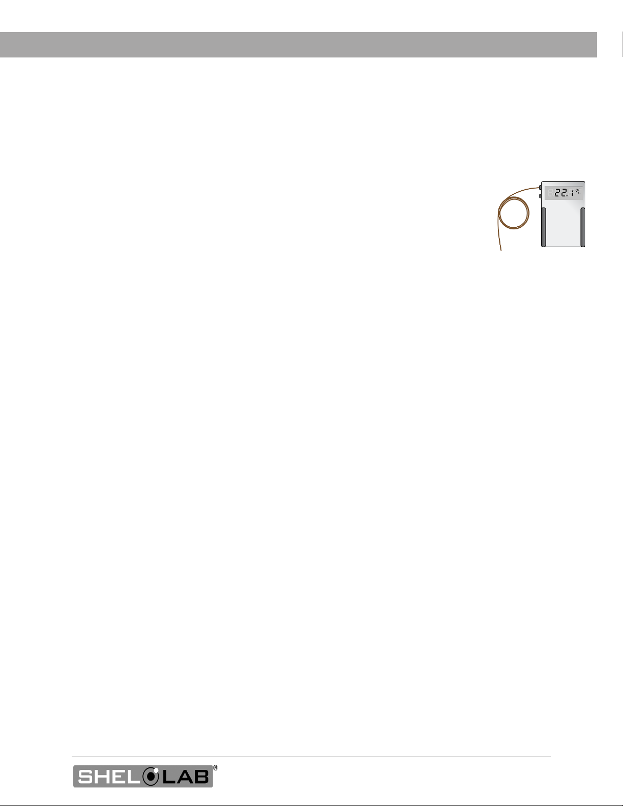
REFERENCE SENSOR DEVICE
Must be purchased separately
A reference sensor device is required for calibrating the oven temperature display.
Reference devices must meet the following standards:
•Accurate to at least 0.1°C
The device should be regularly calibrated, preferably by a third party.
Temperature Probes
Use a digital device with wire thermocouple probes that can be introduced into the unit chamber
through the door space. Select thermocouples suitable for the application temperature you will be
calibrating at.
Why Probes?
Reference readings taken outside the chamber using wire temperature probes avoid chamber door
openings. Openings disrupt the chamber temperature. Each disruption requires a minimum 1-hour wait
to allow the atmosphere to re-stabilize before continuing.
No Alcohol or Mercury Thermometers
Alcohol thermometers do not have sufficient accuracy to conduct accurate temperature calibrations.
Never place a mercury thermometer in the unit chamber. Always use thermocouple probes.
Temperature
Reference

10 | Page
INTRODUCTION
11 | Page
RECEIVING YOUR OVEN
INSPECT THE SHIPMENT
•When a unit leaves the factory, safe delivery becomes the responsibility of the carrier.
•Damage sustained during transit is not covered by the manufacturing defect warranty.
•Save the shipping carton until you are certain that the unit and its accessories function
properly.
When you receive your unit, inspect it for concealed loss or damage to its interior and exterior. If you
find any damage to the unit, follow the carrier’s procedure for claiming damage or loss.
1. Carefully inspect the shipping carton for damage.
2. Report any damage to the carrier service that delivered the unit.
3. If the carton is not damaged, open the carton and remove the contents.
4. Inspect the unit for signs of damage. See the orientation depictions on the next pages as a
reference.
5. The unit should come with an Installation and Operation Manual and a Temperature Program
Manual.
6. Verify that the correct number of accessories has been included.
7. Carefully check all packaging for accessories before discarding.
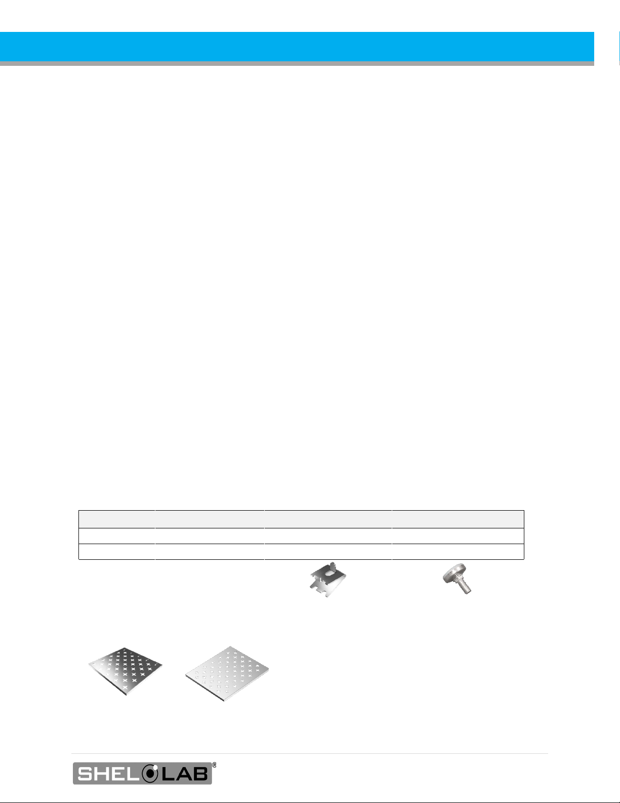
Included Accessories
Model Shelves Shelf Clips Leveling Feet
SMO14HP-2
6
24 Clips
4
SMO38HP-2
12
48 Clips
4
Shelf Types
SMO14HP-2 SMO38HP-2
12 | Page
RECEIVING
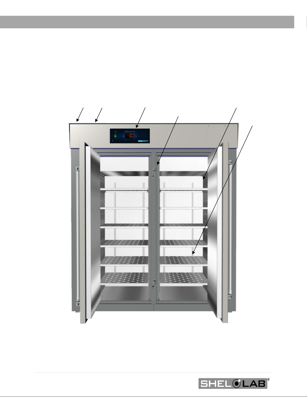
ORIENTATION IMAGES
Temperature Sensor Probes
Control Panel
Exhaust Vent
Intake Vent
Chamber Gasket
Shelf Standard
Mounting Rail
SMO38HP-2
Note: The unit has a single oven chamber with two doors.

13 | Page
SMO14HP
-2
RECEIVING
Intake Vent
Exhaust Vent
Control Panel
Chamber Gasket
Temperature Sensor Probes
Shelf Standard Mounting Rail
Note: The unit has a single oven chamber with two doors.


15 | Page
RECEIVING
Power Panel (back of ovens)
Oven Vents
Exhaust
Intake
Permanent Connect Wire Braid 6-gauge, 6 inches (150 mm)
Accessory Outlet, NEMA 6-20R
Fuse Holders for Accessory Outlet (2 amps each)
Power Supply Wiring Braid
16 | Page
RECEIVING
RECORD THE DATA PLATE INFORMATION
The data plate contains the unit model number, serial number, part number, and part ID. Customer
Support will need this information during any support call. Record it below for future reference.
•The data plate is located on the back of the oven, next to the power inlet.
Plate Information
MODEL NO:
SERIAL NO:
PART NO:
PART ID:

17 | Page
INSTALLATION
HARDWIRE REQUIREMENT
The oven requires permanent connect wiring (commonly known as hardwiring). Wiring to the power
source must be performed by a qualified electrical technician. All other Installation steps can be
performed by the end-user.
INSTALLATION CHECKLIST
For installing the unit in a new workspace location.
Pre-Installation
Check that the required ambient conditions for the unit are met, page 18.
Check that the spacing clearance requirements are met, page 18.
•Unit dimensions may be found on page 55.
Check that a suitable permanent connect electrical power supply is present, page 19.
Install the oven in a suitable workspace location
Review the lifting and handling instructions, page 20.
Install the unit leveling feet, page 21.
Install the oven in its workspace location, page 21.
•The oven may be connected to its power supply after this procedure.
Set up the oven for use
Clean and disinfect the unit and shelving (recommended), page 22.
Install the shelving, page 23.

18 | Page
INSTALLATION
REQUIRED AMBIENT CONDITIONS
This oven is built for use indoors at room temperatures between 15°C and 40°C (59°F and 104°F), at no
greater than 80% Relative Humidity (at 25°C / 77°F). The ambient temperature should not change by
2°C (3.6°F) or more during operation.
When selecting a location to install the unit, consider all environmental conditions that can affect its
temperature performance. These include:
•Proximity to other ovens, autoclaves, and any device producing significant radiant heat
•Heating and cooling vents or other sources of fast-moving air currents
•High-traffic areas
•Direct sunlight
REQUIRED CLEARANCES
These clearances are required to provide sufficient air flows for ventilation and cooling.
6 inches (152 mm) of clearance is required from the sides and from the vent fan on the back of the
oven. Always keep the fan unobstructed.
12 inches (305 mm) of clearance is required from the back of the oven.
24 inches (610 mm) of headspace clearance is required between the exhaust vent and any
overhead cover or partition.
•12 inches (305 mm) of vertical headspace clearance will suffice if the oven exhaust is
vented from the workspace through a duct or other channeling.
Do not place objects on top of the oven. Exception: A power exhaust blower offered by Shel Lab
may be mounted on the exhaust vent.
Door Swing
SMO14HP-2: 24.9” (632 mm)
SMO38HP-2: 28.6” (727 mm)
24” (610 mm)
12” (305 mm)
Headspace with
Ducting Attached
6” (152 mm)
6” (152 mm)
Fan
6” (152 mm)
12” (305 mm)
19 | Page
INSTALLATION
POWER SOURCE REQUIREMENTS
When selecting a location for the oven, verify that each of the following requirements is satisfied:
Power Supply: The power supply must meet the power requirements listed on the oven data plate.
These ovens are intended for 220 – 240V, 50/60 Hz applications at the following amperages:
Model Amperage Model Amperage
SMO14HP-2 26.0 SMO38HP-2 50.0
•Supplied voltage must not vary more than 10% from the data plate rating. Damage to the
unit may result if the supplied voltage varies more than 10%.
•The power source must be single (1) phase and protective earth grounded.
•Use a separate circuit to prevent loss of the unit due to overloading or circuit failure.
•The power source must conform to all national and local electrical codes.
Switch or Circuit Breaker Required: A switch or circuit-breaker must be used in the building
installation to protect against overcurrent conditions. The recommended circuit-breakers are:
•SMO14HP-2 30 amps
•SMO38HP-2 60 amps
Power Feed Disconnect: The oven must be positioned so that all end-users have access to the
power feed disconnect in case of emergencies.
•The disconnect must be in close to the equipment and within easy reach of the end-user.
•The disconnect must be marked as the disconnecting device for the equipment.
Accessory Outlet Fuses: The oven is also provided with a pair (2) of 2-amp fuses installed adjacent to
the external power receptacle used to power accessory blower fans.
•The fuses protect against overcurrent conditions related to the operation of any
attached exhaust blower.
•If one fuse blows, the receptacle will depower. Always find and fix the cause of a blown
fuse prior to putting the unit back into operation.
These fuses do not provide protection against overcurrent events associated with major components
of the oven. Overcurrent protection for the oven must be set up in the location power supply external to
the unit. See the circuit breaker requirements.

20 | Page
INSTALLATION
POWER FEED WIRING
The oven comes provided with an integral 6-inch (150 mm) wire braid consisting of:
•Two 6-gauge hot wires and a 6-gauge earth ground.
The wires for power source connection should be in accordance with the following for all units:
•Green/Yellow – Earth
•Black – Hot
•Black – Hot
The oven must be earth grounded using the protective conductor terminal (green with yellow stripe
wire). Do not remove the protective conductor (earth connection). Removing the protective conductor will
negate the oven protections against potentially dangerous electric shocks and create a possible fire
hazard.
LIFTING AND HANDLING
The unit is heavy. Use appropriate lifting devices that are sufficiently rated for these loads. Follow these
guidelines when lifting the unit.
•Lift the unit only from its bottom surface.
•Doors, handles, and knobs are not adequate for lifting or stabilization.
•Restrain the unit completely while lifting or transporting so it cannot tip.
•Remove all moving parts, such as shelves and trays, and lock doors in the closed position
during transfers to prevent shifting and damage.
Other manuals for SMO38HP-2
1
This manual suits for next models
1
Table of contents
Other Shel lab Oven manuals

Shel lab
Shel lab HF2-2 Quick start guide

Shel lab
Shel lab SGO5-2 User manual

Shel lab
Shel lab SMO5CR-2 Quick start guide

Shel lab
Shel lab CAT180 User manual

Shel lab
Shel lab FX14-2 Quick start guide

Shel lab
Shel lab HF10-2 Quick start guide

Shel lab
Shel lab SHELOLAB SVAC1 User manual

Shel lab
Shel lab SMO38HP-2 User manual
Popular Oven manuals by other brands


GE
GE JTP30DPBB Dimensions and installation information

Tricity Bendix
Tricity Bendix SB 422/423 Operating and installation instructions

GE
GE SCB1001MSS Dimension Guide

Indesit
Indesit IF 51 K.A operating instructions

Ninja
Ninja FOODI SP101ANZ instructions

GE
GE Profile Advantium PSB9240DFBB use and care manual