SHENZHEN ANHUA OPTOELECTRONICS TECHNOLOGY H6 User manual
H6 EVM User's Guide WI-EL00021(V01)
page1 of 5
H6 Evaluation Module (EVM)
User Guide V1.0
Copyright
©Copyright 2015 SHENZHEN ANHUA OPTOELECTRONICS TECHNOLOGY C.,LTD
No content of this file may be copied, revised, reproduced or transmitted in any form or published
without the prior written permission of the company.

H6 EVM User's Guide WI-EL00021(V01)
page2 of 5
1. This user’s guide presents an overview of the Anhua H6evaluation module (EVM) that
incorporates TI DLP DLP3010 (.3 720p) DMD and a general description of the main features
and functions. It will explain the first steps to get started and the main connectors.
2. Applicable Documents
The following documents are applicable to this EVM and are available at www.ti.com.
• DLP3010 (.3 720p) DMD data sheet, TI literature number DLPS051
• DLPC3438 controller data sheet, TI literature number DLPS035A
• Software Programmer's Guide, TI literature number DLPU020A
If you need assistance refer to the DLP and MEMS TI E2E community support forums.
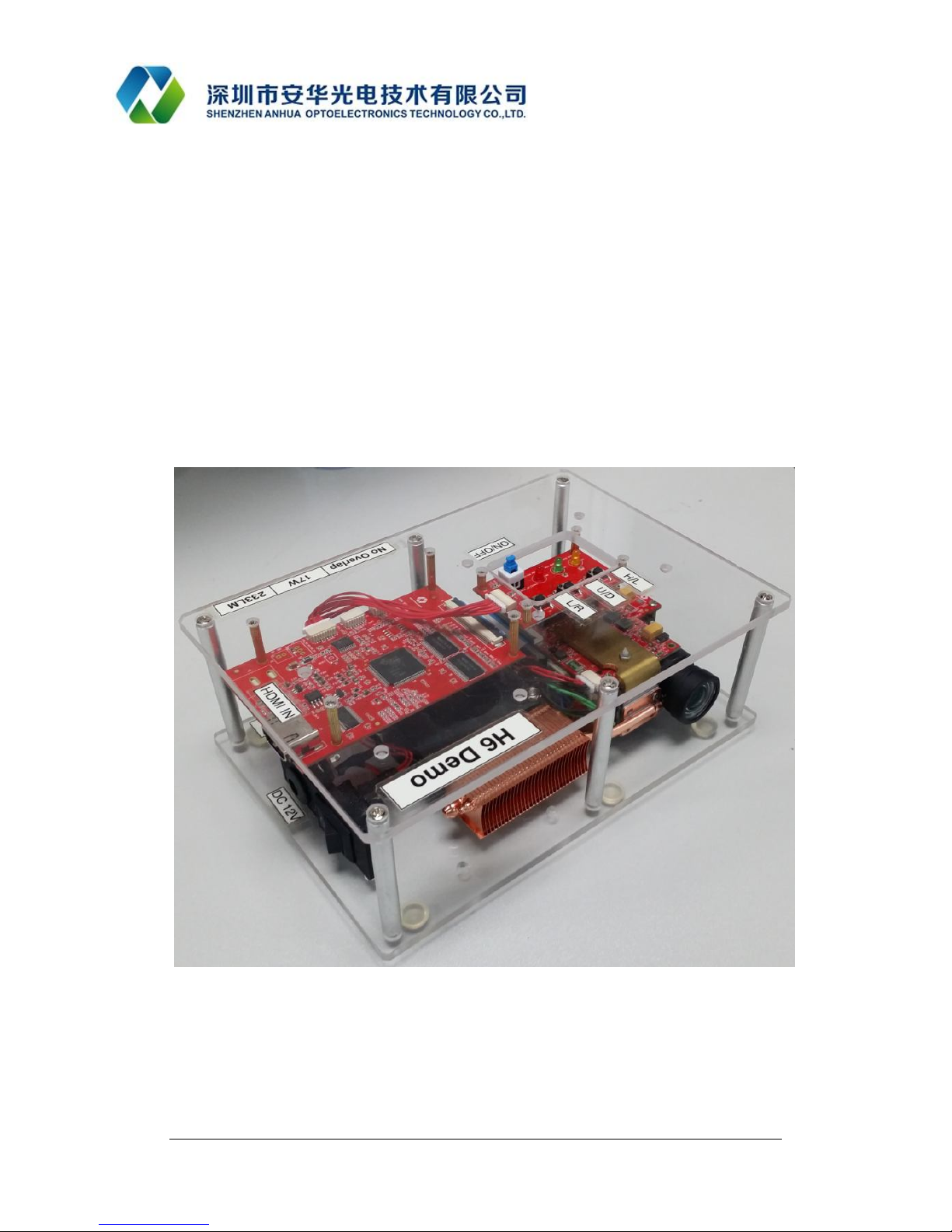
3. What is in the H6 EVM?
H6 EVM consists of two subsystems:
• Light engine – includes the optics, red, green, and blue LEDs, and the 1280x720 (.3 720p)
DMD.
• Driver board – includes the DLP chipset comprising of DLPC3438 Controller and
DLPA2005 PMIC/LED driver. Also includes other system components like MSP430,
HDMI receiver and HDMI connector for external HDMI inputs.
4. EVM Specs:
H6 OE incorporating TI DLP DLP3010 (.3 720p) DMD
Display resolution:1280x720
OE Dimension: 8.15 x5.6 x1.47 (cm) (2.1 cm projector lens)
EVM Dimensions: 17 x11.8 x5.8 (cm)
5. EVM interfaces.
Source Input: HDMI/DVI
Input Resolution:1280x720
Power supply: 12V (5A)
Figure 1 Input interfaces

H6 EVM User's Guide WI-EL00021(V01)
page3 of 5
6. Main board specs:
Board dimensions: 8cmx5.5cm*1.8cm (PCB: 2MM)
Source Input: HDMI/DVI
Input Resolution:1280x720
Power supply: 12V
Figure 2 Main board
7. EVM function keys and LED indicators:
System switch: The system will run when this switch is pushed down, otherwise the
system is shutdown;
Function key 1: Press it to flip the image along the long side;
Function key 2: Press it to flip the image along the short side;
Function key 3: Unused;
System running status LED(Orange): LED is ON when the system is running
Power status LED (Green): LED is flashing after power supply is connected
LED(Red): Unused.

H6 EVM User's Guide WI-EL00021(V01)
page4 of 5
Figure 3 Function keys and LED indicators
Focus lever: Focus the image by toggling the lever (up or down)
Figure 4 Focus lever
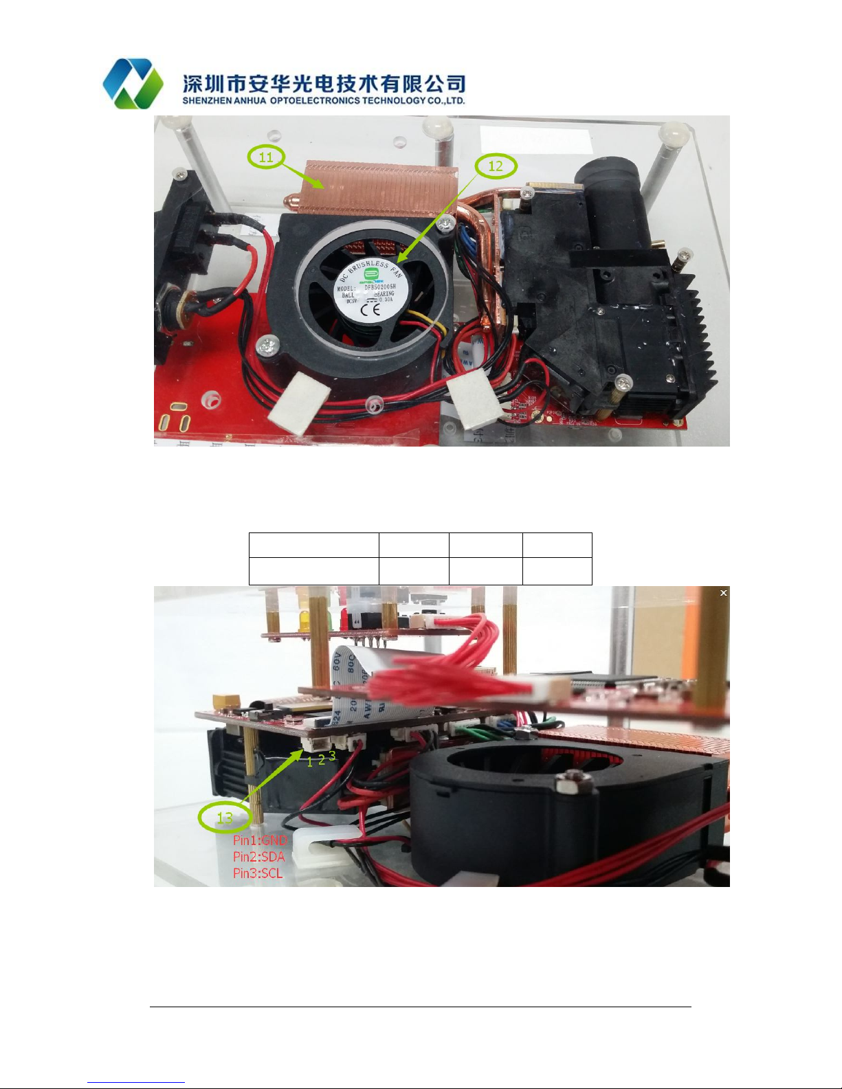
Radiator and cooling fan: Radiator and cooling fan are used to dissipate the heat emitted
from LEDs.
H6 EVM User's Guide WI-EL00021(V01)
page5 of 5
Figure 5 Radiator and Cooling fan
DLPC3438I2C interface: In figure 5, shows the I2C interface connected toDLPC3438, the
Pin definition as the following table.
Pin Number 1 2 3
Signal Name GND SDA SCL
Figure 6 I2C Interface
DLPC3438 can be connected to the external MCU or DLP LightCrafter Display EVM
GUI tool for command and control. Using the GUI tool customers can runtime control
and configure the DLPC3438 functionality.

H6 EVM User's Guide WI-EL00021(V01)
page6 of 5
Steps to connect the I2C interface are:
1. Download the DLP LightCrafter Display EVM GUI tool. Please refer the GUI tool user
guide for more details.
2. Purchase the DeVaSys USB-I2CIO interface board. DeVaSys USB-I2CIO board is a
device that converts USB signal into I2C signal, it is used to implement communication
between DLPC3438 and DLP LightCrafter Display EVM GUI tool.
3. J4 is the I2C interface on DeVaSys USB-I2CIO board. Connect SCL,SDA and GND
respectively between J4 and terminal ⑬ on figure 6, and then connect computer and
DeVaSys USB-I2CIO board with USB Cable. After system power up the communication
between the PC and DLPC3438 will be enabled to control and configure the DLPC3438
runtime.
Figure 7 DeVaSys USB-I2CIO
8. Quick-Start Procedure:
Power up the EVM by applying an external DC power supply (12 V DC, 5.0 A) . Note:
Use an AC-DC switching power supply which accepts 50-60Hz 100-240VAC inputs, and
outputs a nominal 12 VDC at maximum 5 A output current.
Pushed down the system switch, after a few seconds, you can see the projection screen
from EVM.
The focus of the image can be adjusted with the focus wheel on the optical engine.
Plug the HDMI Source in the HDMI connector. Some computers may need to modify the
display setting for outputting the right resolution (1280 x 720).
EVM will detect the HDMI source and will display the selected source automatically.
If you need to flip the image, press the function key 1or 2.
When turning off the EVM, turn off the SW_ONOFF switch prior to removing power
cable. Note: To avoid potential damage to the DMD it is recommended to turn off the
projector with the SW_ONOFF before disconnecting the power.

H6 EVM User's Guide WI-EL00021(V01)
page7 of 5
9. Troubleshooting:
If the EVM is not running please check the power supply (12V,5A) and ensure its
connected and powered on.
White dots or No image. Please check the flex cable connecting the board with the optical
engine.
Either Red, Green or Blue color not showing. Please check the LED cables connecting the
board with the LEDs on the optical engine..
Make sure Fan is running and is not blocked by anything.
Table of contents


