Shireen 18-850 User manual

Shireen Inc Dual Band Repeater Amplifier
W
i
re
l
e
ss
R
e
p
ea
t
e
r
I
n
s
t
a
ll
a
t
i
on
M
a
n
u
al v 1.0
Dual Band
R
e
p
e
a
t
er Amplifier
M
ode
l
:
I
t
e
m
#
18
-
850
Copyright © 2009 Shireen Inc
All Rights
Reserved
#7636A Standish Pl, Rockville, MD 20855, USA
Copyright of this guide belongs to Shireen Inc.
Reproduction, distribution or revision of part or all of contents in this manual in any form
without
written
permission of Shireen Inc is
prohibited.
The information in this guide is subject to change due to function
improvement, design
alteration,
etc. without any prior
notification.
Shireen Inc. 7636A Standish Pl. Rockville, MD 20855 Tel:
301-838-4380
www
.
shireeninc
.
com

Shireen Inc Dual Band Repeater Amplifier
Shireen Inc. 7636A Standish Pl. Rockville, MD 20855 Tel:
301-838-4380
www
.
shireeninc
.
com
2
SAFETY
FIRST
For your safety and to prevent injury to the installer or the operator, it is essential to read
this
manual carefully before your new unit is installed and operated.
Personal
safety
1) This unit is powered by small AC adaptor unit. Turn off the electric supply
if you have to
do
any rewiring or if you are making alterations to wall
sockets.
2) The equipment should be used only for amplifying mobile (cellular) phone
signals and not for
any
other
purpose.
3) Should the unit fail to operate, repairs should be carried out by qualified
personnel ONLY.
4) Before drilling make sure you know the location of existing electrical wiring to
avoid contact
with
the wiring which could cause an electrical shock and severe
the
wiring.
5) If a ladder is required for installation, make sure that the ladder isplacedon a
flat surface and
that it
is securely fixed. It is highly recommended that you
have
someone to
assist you while you are on a
ladder.

Shireen Inc Dual Band Repeater Amplifier
Shireen Inc. 7636A Standish Pl. Rockville, MD 20855 Tel:
301-838-4380
www
.
shireeninc
.
com
3
Table of
Contents
1. General....................................................................................................
4
1.1. Purpose
.............................................................................
4
1.2.
Scope.................................................................................
4
1.3.
Responsibility...................................................................
4
2. Preparing to install Item #
18-850
.....................................................
5
2.1. Overview
..........................................................................
5
2.2. Check for signal
strength
.................................................
6
2.3. Determine the Needed Coverage
Area
...........................
6
2.4. Location of Outdoor Antenna and Indoor
Antenna
........
6
2.5. Cable
Requirements.........................................................
7
2.6. Power
Requirements
........................................................
7
2.7. Installing Tools
Needed...................................................
7
3. Installing Item#18-850.......................................................................
8
3.1. Package
Contents
.............................................................
8
3.2. Installing the Outdoor
Antenna
.......................................
9
3.3. Installing the Indoor Antenna
..........................................
9
3.4. Running the feeder cables to the Item#18-850
..............
9
3.5. Mounting the
Item#18-850..............................................
9
3.6. Operating the
repeater....................................................10
4. Maintenance and
Troubleshooting
.................................................
12
4.1. Normal Repeater
Operation...........................................12
4.2. Abnormal Repeater Operation and
Troubleshooting....12
Appendix A
13
Specifications
..........................................................................13
Appendix B
15
Block
Diagram
.......................................................................15

Shireen Inc Dual Band Repeater Amplifier
Shireen Inc. 7636A Standish Pl. Rockville, MD 20855 Tel:
301-838-4380
www
.
shireeninc
.
com
4
1.
G
e
n
era
l
The Item#18-850 dual band cellular repeater will improve RF coverage for areas with
low signal strength or where there is patchy Indoor from the cell phone Indoor
provider
.
1.1 Purpose
The purpose of this document is to provide specific In-door Solutions methods and
procedures for Field
RF
Engineering.
1.2 Scope
This document covers four (4) main areas
:
1) Preparing to install the wireless
repeater
2) Installing the wireless
repeater
3) Operating the wireless
repeater
4) Maintenance and
Troubleshooting
1.3 Responsibility
Field RF Engineering shall be responsible for the subject matter contained here in. The
document shall
be
reviewed on a regular basis to ensure
accuracy.

2. Prep
a
2.1
O
The first
t
to install
works.
1) T
h
2) T
h
3) T
h
h
o
4) I
d
y
o
o
u
o
b
c
e
S
hir
e
e
n
a
ring to inst
a
O
verview
t
hing you n
e
the repeater
h
e cellular s
i
h
e Outdoor
h
e wireless
r
o
me/office.
d
eally, the
I
o
ur home/o
f
u
tside your
b
structions
(
e
ll site – an
e
n
I
nc. 7636
A
a
ll Item # 1
8
e
ed to do be
f
. Look at th
e
i
gnal is
b
ro
a
Antenna co
l
r
epeater (Ite
m
I
tem#18-85
0
f
fice in ord
e
home/offic
e
(
buildings,
c
e
levated po
s
A
S
t
andi
s
h
P
l
8
-850
f
ore installi
n
e
diagram b
e
a
dcasted to
a
l
lects the si
g
m
#18-850)
a
0
and Indo
o
e
r to maxi
m
e
, facing to
w
c
ars, trees e
s
ition often
h
Cell
Phone
Shireen I
n
l
.
R
ock
v
il
l
e
,
n
g wireless
r
e
low for an
i
a
nd from the
g
nal from th
e
a
mplifies th
e
o
r Antenna
s
m
ize covera
g
w
ards the c
l
tc), or it sh
o
h
elps this.
B
n
c Dual Ban
d
M
D 20855
r
epeater is t
o
i
dea of how
cell site.
e
cell site.
e
signal and
s
hould be p
g
e. The out
d
l
osest cellul
o
uld have l
i
B
TS
Power
Supply
d
Repeater
A
T
e
l
:
301-8
3
o
find out w
h
the Cellula
r
re-broadcas
laced centr
a
d
oor Anten
n
ar site havi
n
i
ne of sight
A
mplifie
r
3
8-4380
h
ere you wa
n
r
Repeater
ts it to your
a
lized insid
e
n
a should b
e
n
g the leas
t
towards th
e
5
n
t
e
e
t
e

Shireen Inc Dual Band Repeater Amplifier
Shireen Inc. 7636A Standish Pl. Rockville, MD 20855 Tel:
301-838-4380
www
.
shireeninc
.
com
6
2.2 Check for signal strength
Before installing the Item#18-850 in your home/office, make sure that you can place calls on
the outside of
your
home/office or in the attic or at roof level where you install the Outdoor
Antenna. The Item#18-850 can only
bring
cell phone signals into your home/office if cell
phone signals are reaching the outside of your home/office,
your
attic or at roof
level. T
he
best way to find the cellular signal around your home/office is simply to walk around with
your
cell
phone ON. You should use a cell phone on the network/band whose signal you are
trying to improve. The
“Signal
Strength” meter on your cell phone will tell you where the
signal is strongest. The Cell Phone “Signal
Strength”
meter takes up to 6~10 seconds to
update as you move from location to location, so make sure to take a nice
long
pause in every
location you test. The place you choose should either be outside, or in the very least by a
window.
If you can reliably make and receive calls outside your home/office, then Item#18-
850 can
bring
the signal into your home/office. If only one signal bar is displayed on your
cell phone, indoor coverage
will
be limited to one small room or
area.
Caution
:
Cell Phone Signal bars are approximate and vary for each model of
phone.
The number of bars can fluctuate widely, depending on the
exact location
of
the phone, position or angle of the phone, weather,
etc. Most cell
phone
signal meters update every 6 to 10 seconds. An
increase of only one
bar
typically indicates a 4x
to
10x signal
increase. The best indicator of coverage area is your ability
to
reliably place and receive
calls.
2.3 Determine the Needed Coverage Area
Identify the location in your home/office where you need signal coverage Item#18-850 can
cover approximately 2000 ft. the type of antennas used will dictate the exact coverage area.
Coverage varies based
on
outdoor signal level, building construction, and general installation.
Walls, ceilings or floors
will
reduce the coverage
area.
2.4 Location of Outdoor Antenna and Indoor Antenna
It is recommended that the Outdoor Antenna and Indoor Antenna have approximately 15
feet of vertical separation. If the antennas are too close together, the LED’s will turn RED
indicating Oscillations. Place the Outdoor Antenna as high as possible
to
capture the best
signal.

Shireen Inc Dual Band Repeater Amplifier
Shireen Inc. 7636A Standish Pl. Rockville, MD 20855 Tel:
301-838-4380
www
.
shireeninc
.
com
7
2.5 Cable Requirements
Coaxial cable is needed to connect the Item#18-850 with the antennas. For the best
performance, cables must be low
loss. Shireen Inc is a leader in the RF cable Industry,
please contact us for any custom lengths or specialized cable requirements.
2.6 Power Requirements
The Item#18-850 can be plugged into a standard 2-prong 100~240VAC receptacle using
the included AC/DC Power Adaptor. The Power Adaptor consumes less than
15W. The
DC power supported is 5Vdc with a max. current draw of 2A.
WARNING The Item#18-850 MUST only be used with the provided
power adaptor. Use of other power adaptors will void the
warranty and may damage
the
repeater.
2.7 Installing Tools Needed
The following tools are needed to install
Item#18-850:
1. #2
screwdriver
2. Cellular phone operating in the band supported by the
Item#18-850
3.
Drill for wall mounting purposes.
Shireen Inc Dual Band Repeater Amplifier
Shireen Inc. 7636A Standish Pl. Rockville, MD 20855 Tel:
301-838-4380
www
.
shireeninc
.
com
8
3. Installing
I
tem#18-850
3.1 Package Contents
Before you begin, make sure all of the following parts included in the
box.
No
Quantity
Description
1
1
Dual Band Repeater
(Cellular)
2
1
AC/DC Power
Adaptor
3
1
Quick Installation
Guide
CAUTION
The Outdoor Antenna, Indoor Antenna, Feeder Cables
and
Bracket for antenna mounting should be previously prepared
by regional
RF
Field Engineer for installing the
Item#18-
850.

Shireen Inc Dual Band Repeater Amplifier
Shireen Inc. 7636A Standish Pl. Rockville, MD 20855 Tel:
301-838-4380
www
.
shireeninc
.
com
9
3.2 Installing the Outdoor Antenna
Follow the antenna installation procedures provided by
SHIREEN INC
3.3 Installing the IndoorAntenna
Follow the antenna installation procedures provided by
SHIREEN INC
3.4 Running the feeder cables to the Item#18-850
Follow the antenna installation procedures provided by
SHIREEN INC
3.5 Mounting the Item#18-850
The wireless repeater can be installed on a flat surface or wall at the location designated
for installation.
1) General Installation
Guidelines
The installation location should be within 3m of an AC power
outlet
The location should not be easily accessible; this will help prevent any
changes in performance of the
repeater.
The power adaptor should be fixed harder and tighter in order to
prevent loose connections to the
socket.
The antenna port location should have enough space so that the feeder line
can be connected easily.
Locations where wall’s surface is fragile and can be easily broken should be
avoided
.
Outdoor coaxial antenna cable should be properly ground for lightning
protection.

Shireen Inc Dual Band Repeater Amplifier
Shireen Inc. 7636A Standish Pl. Rockville, MD 20855 Tel:
301-838-4380
www
.
shireeninc
.
com
10
3.6 Operating the repeater
Basic Concepts: RF Isolation Check
RF isolation is defined by the path loss or attenuation, between the Outdoor and Indoor
antenna. It is important
to
ensure that the two antennas are sufficiently separated, such that
the signal transmitted by one antenna is
not
received by the other. For optimal performance,
the separation of the two antennas must provide a path loss
of
at
least 12 dB greater than the
gain of the repeater. Therefore, the Item#18-850 requires at least 57~ 72dB
of
attenuation
between the antennas.
In most cases, isolation will be achieved by properly locating the Outdoor and interior
coverage
antennas (Indoor antenna), respectively. The optimal location for the Outdoor
antenna is high above the
roof
line, and exterior to the
building.
The interior coverage antenna (Indoor antenna) should be installed inside, near or below
the ceiling. Following these guidelines should ensure adequate isolation between
antennas.
oNever mount the Outdoor or coverage antenna near a window, where Signal
can easily pass
through
the
glass
oMount the Outdoor antenna as high as physically possible to the exterior of the
building, maximizing the vertical separation between antennas and pointing away
from the building, toward the
base
station
site.
oInstall the antennas taking advantage of any existing building structure. Such as
brick walls,
metal
roofs, or multiple wall structures to additionally attenuate the
path between
them.
oWhen using directional antennas inside the building to cover corridors and
hallways, point
the
interior antenna away from the Outdoor antenna
location.
oIn extreme cases, the building configuration may not allow for such
separation and isolation.
If
additional isolation is required, coaxial attenuation
may be inserted between the Outdoor
antenna
and the repeater, with the
potential compromise to the coverage within the
building
oThe flow of the isolation check functionality for the Item#18-850 is as
follows.

Shireen Inc Dual Band Repeater Amplifier
Shireen Inc. 7636A Standish Pl. Rockville, MD 20855 Tel:
301-838-4380
www
.
shireeninc
.
com
11
Step 1) Isolation Check
Start
After “POWER ON”, the repeater is checking the status
automatically. T
he Isolation
Checking time is a Max. of 10secs and LED’s turn
ON/OFF repeatedly.
Step 2) Internal Parameter
Setup
It will be check the controller and set up initial parameters. Both LEDs green
Step 3) Isolation Value Check between Outdoor and Indoor
antennas.
If in step one the Isolation was found to be insufficient the LEDs will turn RED
indicating oscillations and the internal amplifiers will be turned off, so the current draw
will be reduced.
Step 4) High power input Checking during operation
When the repeater is working, the signal coming into the unit is being constantly
monitored, if the signal is strong the Green LED will start to blink, indicating that the
Signal is strong, but if the signal is excessively high then the LED will turn into Blinking
RED.

Shireen Inc Dual Band Repeater Amplifier
Shireen Inc. 7636A Standish Pl. Rockville, MD 20855 Tel:
301-838-4380
www
.
shireeninc
.
com
12
4. Maintenance and
T
r
oubl
es
hoo
t
ing
In most cases, problems with the Item#18-850 can be diagnosed using the Repeater Unit
LED
indicators
4.1 Normal Repeater Operation
The Repeater Unit has two LEDs, marked as D1 and D2 respectively, after the power on
self test both the LEDs become GREEN. This indicates normal operation.
If the input signal is strong then the LEDs will start blinking Green. The operation of the
unit will not be affected and will be considered normal. Blinking green LED is only an
indicator that the signal coming into the amplifier is strong.
4.2 Abnormal Repeater Operation and Troubleshooting
When the Repeater is powered ON, it runs a self test program. If there are any
oscillations on the board the LEDs will stay RED and the amplifier section of the repeater
will be turned off to avoid damage to the hardware.
During normal operation the LEDs are either green or Blinking green. If the input to the
repeater is very high the LED will start to Blink RED. This indicates that the signal
coming into the repeater is too high.
In such a case the repeater location should be changed or the cable length between the
antenna and the repeater should be extended in order to decrease the input to the repeater.

Shireen Inc Dual Band Repeater Amplifier
Shireen Inc. 7636A Standish Pl. Rockville, MD 20855 Tel:
301-838-4380
www
.
shireeninc
.
com
13
Appendix
A
Electrical Specifications:
Frequency : Uplink: 824-849 MHz and 1850-1910 MHz
Downlink: 869-894 MHz and 1930-1990 MHz
Technology : CDMA/GSM
Max Output Power : 824-849 MHz : +29 dBm
1850-1910 MHz : +25 dBm
Dynamic Variable Gain : 824-849 MHz : 50 dB (min) thru 55 dB (max)
1850-1910 MHz : 45 dB (min) thru 55 dB (max)
Average Gain : 50 dB
Absolute Max RF Input : 824-849 MHz : -20 dBm
1850-1910 MHz : -20 dBm
Impedance : 50 ohms
Power Consumption : Standby = 1A @ 5Vdc :: Max 2A @ 5Vdc
General Specifications:
Power Supply : 5 VDC, 3A
RF Connections : Outside Antenna Port: Type-N
Inside Antenna Port: Type-N
Indicator : LEDs shows normal operation and some troubleshooting indications
Shireen Inc Dual Band Repeater LED Functions
D1 1900MHz band
D2 850MHz band
Shireen Inc Dual Band Repeater Amplifier
Shireen Inc. 7636A Standish Pl. Rockville, MD 20855 Tel:
301-838-4380
www
.
shireeninc
.
com
14
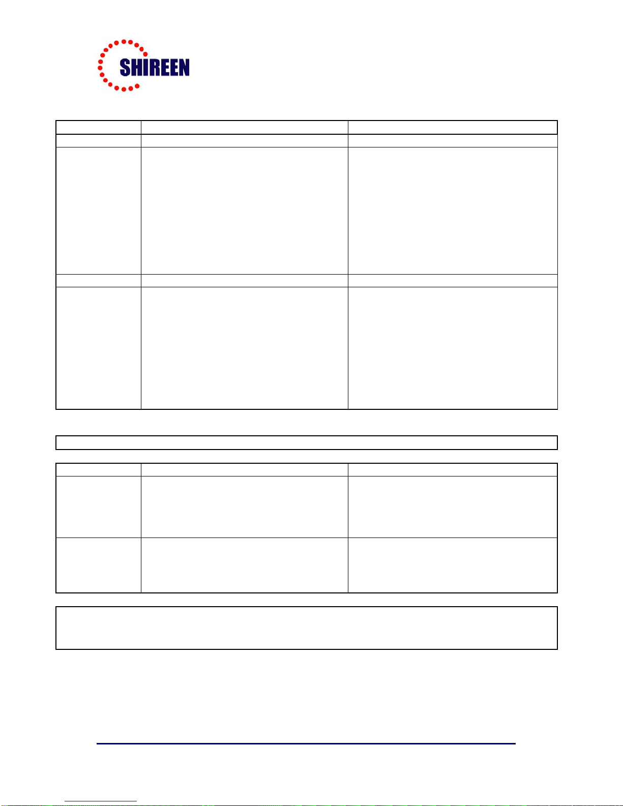
D1 D2
Red Oscillations - Unit will turn off Oscillations - Unit will turn off
Blinking Red
Strong signal coming from Base station:
Operation will be unaffected: In order to avoid
saturation of the repeater, the Installer can
increase the cable length between antenna
and dual band repeater, such that the LED
indicator on the repeater shows a Green light.
It should be noted that the amplifier
functionality will not be affected by this and
the signal coming in will get amplified. Please
see datasheet for max. input and output
power settings.
Strong signal coming from Base station:
Operation will be unaffected: In order to avoid
saturation of the repeater, the Installer can
increase the cable length between antenna
and dual band repeater, such that the LED
indicator on the repeater shows a Green light.
It should be noted that the amplifier
functionality will not be affected by this and the
signal coming in will get amplified. Please see
datasheet for max. input and output power
settings.
Green Normal Operation Normal Operation
Blinking Green
Strong signal coming from the cell phone into
the Dual band repeater. This signal also
comes up when multiple users are talking
over the cell phone; this indication shows
activity in the respective band. Cell phone
users change their position and talk for a
limited time no action is required when such
an indication is shown.
Strong signal coming from the cell phone into
the Dual band repeater. This signal also
comes up when multiple users are talking over
the cell phone; this indication shows activity in
the respective band. Cell phone users change
their position and talk for a limited time no
action is required when such an indication is
shown.
Internal LED Software settings**
1900MHz band 850MHz Band
Blinking Red
When the amplified output of the dual band
repeater for the signal coming from the BTS
reaches 12dBm the Red LED starts to blink
indicating a strong BTS signal coming into the
dual band repeater.
When the amplified output of the dual band
repeater for the signal coming from the BTS
reaches 20dBm the Red LED starts to blink
indicating a strong BTS signal coming into the
dual band repeater.
Blinking Green
When the amplified output of the dual band
repeater for the signal coming from the cell
phone is high the Green LED starts to blink
indicating cell phone activity
When the amplified output of the dual band
repeater for the signal coming from the cell
phone is high the Green LED starts to blink
indicating cell phone activity
**these settings can be modified by rewriting the software in the dual band repeater unit. The thresholds used to trigger the LED response are as per common
knowledge of cell phone and BTS signal strengths. It is assumed that a high BTS signal indicates possibility that the cell phones will directly communicate with the
BTS and hence, a repeater will not be required for that particular location. This will enable the Installer to choose a proper location for the installation of the repeater
and provide optimum Indoor to the customer.
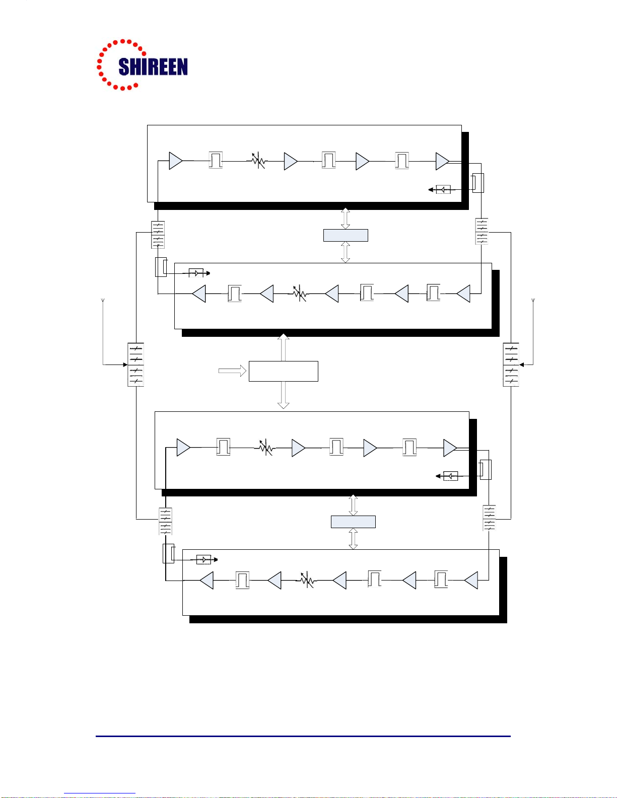
Appendix
B
Block Diagram
Shireen Inc Dual Band Repeater Amplifier
Shireen Inc. 7636A Standish Pl. Rockville, MD 20855 Tel:
301-838-4380
www
.
shireeninc
.
com
15
LNA RF SAW
Filter Digital
Attenuator RF SAW
Filter
RF
AMP BPF RF
AMP Power
Amplifier
Controller
LNARF SAW
Filter
Digital
Attenuator
RF SAW
Filter RF AMP BPF
RF AMP
Power
Amplifier RF AMP
UL Output Detector
UL Output Detector
Duplexer Duplexer
UL (Up Link) Path
UL (Down Link) Path
LNA RF SAW
Filter Digital
Attenuator RF SAW
Filter
RF AMP BPF RF AMP Power
Amplifier
Controller
LNARF SAW
Filter
Digital
Attenuator
RF SAW
Filter RF AMP BPF
RF AMP
Power
Amplifier RF AMP
UL Output Detector
UL Output Detector
Duplexer Duplexer
UL (Up Link) Path
UL (Down Link) Path
DUPLEXER DUPLEXER
INDOOR ANTENNA
OUTDOOR ANTENNA
POWER ADAPTER
(+5V/2A)
AC110-220V ±20%
824-849
MHz
869-894
MHz
1930-1990
MHz
1850-1910
MHz
824-849
MHz
869-894
MHz
1850-1910
MHz
1930-1990
MHz
Table of contents


