Shivvers BLUE FLAME II FH1527C1P240LP Manual

P-13246
01-07-2020
BLUE FLAME II
CROP DRYER FOR SINGLE WIDTH,
SINGLE INLET CENTRIFUGAL FANS
Installation &
Operating Instructions
For Models:
FH1527C1P240LP -- 15 Hp, 1 Phase, 240V, LP, CSA W/ CONTROLS
FH1527C1P240NG -- 15 Hp, 1 Phase, 240V, NG, CSA W/ CONTROLS
FH1527-1P240LP-CSA -- 15 Hp, 1 Phase, 240V, LP, CSA
FH1527-1P240NG-CSA -- 15 Hp, 1 Phase, 240V, NG, CSA
FH1527-3P230LP-CSA -- 15 Hp, 3 Phase, 230V, LP, CSA
FH1527-3P230NG-CSA -- 15 Hp, 3 Phase, 230V, NG, CSA
FH1527-3P460LP-CSA -- 15 Hp, 3 Phase, 460V, LP, CSA
FH1527-3P460NG-CSA -- 15 Hp, 3 Phase, 460V, NG, CSA
FH1527-3P575LP-CSA -- 15 Hp, 3 Phase, 575V, LP, CSA
FH1527-3P575NG-CSA -- 15 Hp, 3 Phase, 575V, NG, CSA
FH2030-3P230LP-CSA -- 20 Hp, 3 Phase, 230V, LP, CSA
FH2030-3P230NG-CSA -- 20 Hp, 3 Phase, 230V, NG, CSA
FH2030-3P460LP-CSA -- 20 Hp, 3 Phase, 460V, LP, CSA
FH2030-3P460NG-CSA -- 20 Hp, 3 Phase, 460V, NG, CSA
FH2030-3P575LP-CSA -- 20 Hp, 3 Phase, 575V, LP, CSA
FH2030-3P575NG-CSA -- 20 Hp, 3 Phase, 575V, NG, CSA
For outdoor installation only.
Use heated air for non-occupied spaces only.
Shivvers Manufacturing, Inc.
614 West English St.
Corydon, IA 50060 USA
Ph. (641)872-1005 ** Fax (641)872-1593

2
www.shivvers.com
WARNING: Improper installation, adjustment, alteration,
service or maintenance can cause property damage, injury or death.
Read the installation, operating and maintenance instructions
thoroughly before installing or servicing this equipment.
WARNING: If the information in this manual is not followed exactly,
a fire or explosion may result causing property damage, personal
injury or loss of life.
-Do not store or use gasoline or other flammable vapors and
liquids in the vicinity of this or any other appliance.
-WHAT TO DO IF YOU SMELL GAS
• Do not try to light any appliance.
• Extinguish any open flames.
• Do not touch any electrical switch.
• Immediately call your gas supplier. Follow the
gas supplier’s instructions.
• If you cannot reach your gas supplier, call the
fire department.
-Installation and service must be performed by a qualified
installer, service agency or the gas supplier.
FOR YOUR SAFETY
The use and storage of gasoline and other flammable vapors and
liquids in open containers in the vicinity of this appliance is hazardous.

3
TABLE OF CONTENTS
PAGE
DEALER INFORMATION ........................……………………………………. 4
INTRODUCTION .....................................…………………………………….……. 5-6
SAFETY INFORMATION ..................................…………………………….…….. 7-8
LOCATION OF SAFETY DECALS ON CROP DRYER ...……………….………. 9-10
LOCATION OF OTHER DECALS ON CROP DRYER ……………………..……. 11-15
IDENTIFICATION OF PARTS ..............................………………………….…….. 16-22
MECHANICAL INSTALLATION …………………………………………………… 23-39
DRYING BIN LAYOUT ………………………………………………………. 24
PAD LAYOUT ………………………………………………………………... 25-26
HEATER INSTALLATION ………………………………………………..…. 27-30
FAN INSTALLATION …………………………………………………..……. 31
FAN CONTROL INSTALLATION …………..….………………………..…. 31
OPERATING CONTROL & TRANSITION HI LIMIT INSTALLATION … 32-36
LIQUID PROPANE INSTALLATION AND GAS HOOKUP …………..… 37-38
NATURAL GAS INSTALLATION AND GAS HOOKUP…..…………..… 39
PAINT …………………….……………..…………………………..………… 39
ELECTRICAL INSTALLATION ………………………………………..…………… 40-48
INCOMING FAN POWER HOOKUP ………………………………...……. 40-41
15 HP C-FAN 1 PHASE WITH VFD INCOMING POWER WIRING…….. 41
OTHER C-FAN INCOMING POWER WIRING ………………………..……. 42
OTHER C-FAN WIRING FROM CONTROL TO MOTOR…………..……. 42
15 HP C-FAN WIRING FROM DRIVE TO MOTOR……………………….. 43
FIELD INSTALLED CONTROL WIRING …………………………….……. 44
TYPICAL FIELD INSTALLED CONTROL WIRING CONDUIT RUNS…. 45
CONTROL WIRING FOR FAN CONTROL PANEL ON BACK OF FAN.. 46-47
INITIAL CHECKOUT ……………………………………………………..….. 48
OPERATING INSTRUCTIONS ………………………………………………………. 49-52
MAINTENANCE ...............................……………………………………………….. 53
OPERATING CONTROL SCHEMATIC ……………………………………………... 54
LP HEATER SCHEMATIC…………………………………………………………….. 55
FAN CONTROL SCHEMATIC …………………….………………………………….. 56
FAN VFD CONTROL SCHEMATIC …………………….………………...………….. 57

4
DEALER INFORMATION
DEALER
Name:
Address:
Phone #:
INSTALLING CONTRACTOR (if different from above)
Name:
Address:
Phone #:
SERVICE CONTRACTOR (if different from above)
Name:
Address:
Phone #:
MODEL: □ FH1527C1P240LP □ FH1527C1P240NG
□ FH1527-1P240LP-CSA □ FH1527-1P240NG-CSA
□ FH1527-3P230LP-CSA □ FH1527-3P230NG-CSA
□ FH1527-3P460LP-CSA □ FH1527-3P460NG-CSA
□ FH1527-3P575LP-CSA □ FH1527-3P575NG-CSA
□ FH2030-3P230LP-CSA □ FH2030-3P230NG-CSA
□ FH2030-3P460LP-CSA □ FH2030-3P460NG-CSA
□ FH2030-3P575LP-CSA □ FH2030-3P575NG-CSA
SERIAL NUMBER:
DATE OF INSTALLATION:

5
INTRODUCTION
COMPLETELY READ THIS MANUAL BEFORE INSTALLING OR USING THE BLUE
FLAME II CROP DRYER (FAN AND HEATER), CSA Version.
This manual is intended for use with the Shivvers 15 or 20 Hp Blue Flame II Crop Dryer
which is CSA (Canadian Standards Association) certified. The Crop Dryer consists of a
Blue Flame II heater connected to a Shivvers 15 or 20 Hp Centrifugal Fan. The heater
may not be used with any other manufacturer’s centrifugal fan. The complete crop
dryer is shipped in three or four separate pieces which must be installed and wired
together at the installation site.
FH1527C1P240LP
118X-001A 15 Hp C-Fan
119M-001A BFII Heater, LP, 15 Hp, CSA
119N-001A Op. Control & H.L.
E-6617 Freq. Drive, 240V,1P
FH1527-1P240LP-CSA
118Y-001A 15 Hp C-Fan, 1 Phase
119M-001A BFII Heater, LP, 15 Hp, CSA
119N-001A Op. Control & H.L.
FH1527-3P230LP-CSA
118X-001A 15 Hp C-Fan
119M-001A BFII Heater, LP, 15 Hp, CSA
119N-001A Op. Control & H.L.
FH1527-3P460LP-CSA
118X-001A 15 Hp C-Fan
119M-001A BFII Heater, LP, 15 Hp, CSA
119N-001A Op. Control & H.L.
FH1527-3P575LP-CSA
118Z-001A 15 Hp C-Fan, 575V
119M-001A BFII Heater, LP, 15 Hp, CSA
119N-001A Op. Control & H.L.
FH2030-3P230LP-CSA
118AA-001A 20 Hp C-Fan
119P-001A BFII Heater, LP, 20 Hp, CSA
119N-001A Op. Control & H.L.
FH2030-3P460LP-CSA
118AA-001A 20 Hp C-Fan
119P-001A BFII Heater, LP, 20 Hp, CSA
119N-001A Op. Control & H.L.
FH1527C1P240NG
118X-001A 15 Hp C-Fan
119Q-001A BFII Heater, NG, 15 Hp, CSA
119N-001A Op. Control & H.L.
E-6617 Freq. Drive, 240V,1P
FH1527-1P240NG-CSA
118Y-001A 15 Hp C-Fan, 1 Phase
119Q-001A BFII Heater, NG, 15 Hp, CSA
119N-001A Op. Control & H.L.
FH1527-3P230NG-CSA
118X-001A 15 Hp C-Fan
119Q-001A BFII Heater, NG, 15 Hp, CSA
119N-001A Op. Control & H.L.
FH1527-3P460NG-CSA
118X-001A 15 Hp C-Fan
119Q-001A BFII Heater, NG, 15 Hp, CSA
119N-001A Op. Control & H.L.
FH1527-3P575NG-CSA
118Z-001A 15 Hp C-Fan, 575V
119Q-001A BFII Heater, NG, 15 Hp, CSA
119N-001A Op. Control & H.L.
FH2030-3P230NG-CSA
118AA-001A 20 Hp C-Fan
119R-001A BFII Heater, NG, 20 Hp, CSA
119N-001A Op. Control & H.L.
FH2030-3P460NG-CSA
118AA-001A 20 Hp C-Fan
119R-001A BFII Heater, NG, 20 Hp, CSA
119N-001A Op. Control & H.L.

6
FH2030-3P575LP-CSA
118AB-001A 20 Hp C-Fan, 575V
119P-001A BFII Heater, LP, 20 Hp, CSA
119N-001A Op. Control & H.L.
FH2030-3P575NG-CSA
118AB-001A 20 Hp C-Fan, 575V
119R-001A BFII Heater, NG, 20 Hp, CSA
119N-001A Op. Control & H.L.
For best results and ease of installation and service, the Shivvers 565D-001A Transition
and 74C-001A or 74D-001A Entrance Collars are recommended.
The Blue Flame II heaters provide from approx. 0.75 million to 3.6 million BTU/Hr of
heat utilizing Liquid Propane or Natural Gas fuel. This heater would not normally be
considered a low temperature rise heater for applications such as drying rice. The LP
Heater is equipped with a built in vaporizer. The pipe train is configured in a hi-low-off
configuration for a wide temperature operating range. A 3-wire thermostat system is
included to control the heater.
This series of Blue Flame II heaters are similar to the centrifugal heaters manufactured
by Shivvers in the past. These dryers use a flame sensing system called flame
rectification. There are no moving parts in the flame rod. It just has to be in the flame
but not touching the burner element or housing. The flame sense module will apply an
AC current to the flame rod. If a flame is present, the flame will rectify or change it to a
DC current. If the flame sense module detects this DC current, it will turn off the ignition
transformer and the burner will continue to burn. If the DC current is not detected, the
flame sense module will lockout the burner, and the heater power switch will have to be
shut off for a few seconds, then turned back on and re-started, to reset the module.
The Blue Flame II Crop Dryers, CSA versions, were first introduced in the fall of 2015.
Additional models were added in 2019.
The equipment shall be installed in accordance with the Natural Gas and Propane
Installation Code, CSA B149.1 and the Propane Storage and Handling Code, CSA
B149.2, or applicable Provincial Regulations, which should be carefully followed in all
cases. Authorities having jurisdiction should be consulted before installations are made.

7
SAFETY INFORMATION
The operator of this machinery must assume the responsibility for his own safety, and
that of those who are working with him. He must also make sure the equipment was
installed properly. Factors that contribute to the overall safety of operation are: proper
use, maintenance, and frequent inspection of the equipment. All of these are the
operator's responsibility.
If any items covered in this manual are not completely understood, or there is a concern
with the safety of the product, contact SHIVVERS Manufacturing Incorporated at the
address shown on the front cover.
SHIVVERS is genuinely interested in providing the safest practical equipment to our
customers. If you have a suggestion which you believe will enhance the safety of this
product, please write us and let us know.
The safety alert symbol will be accompanied by one of three signal words whose
definitions are given as:
DANGER: Red and white. Indicates an imminently hazardous situation that, if not
avoided, will result in death or serious injury. This signal word is to be
limited to the most extreme situations, typically for machine components
that, for functional purposes, cannot be guarded.
WARNING: Orange and black. Indicates a potentially hazardous situation that, if not
avoided, could result in death or serious injury, and includes hazards that
are exposed when guards are removed. It may also be used to alert
against unsafe practices.
CAUTION: Yellow and black. Indicates a potentially hazardous situation that, if not
avoided, may result in minor or moderate injury. It may also be used to
alert against unsafe practices.
TAKE NOTE ANYTIME THIS SAFETY ALERT
SYMBOL APPEARS.
YOUR SAFETY, AND THAT OF PERSONS AROUND
YOU IS AT STAKE.

8
Be sure to observe these common sense rules when working with the dryer equipment:
1). All units must be equipped with a main power disconnect switch. This disconnect
switch must shut power off to the complete drying system. It must have the
capability of being locked into the OFF or OUT position. Disconnect and LOCK
OUT this main power disconnect switch before conducting any inspection,
maintenance, repair, adjustment, or cleaning of the drying system. When you
must have the electrical power on to troubleshoot equipment, do it from a safe
distance, and always from outside the bin.
2). Keep the bin entrances locked at all times. To unlock the bin, first lower the
Level-Dry (if so equipped), then shut the main power disconnect off. Take the
safety lock off the bin entrance and place it on the main power disconnect before
opening the bin entrance. Never enter the drying bin unless the Level-Dry (if
so equipped), is completely lowered, and all power is disconnected and
locked out.
3). Always keep all shields and guards in place. If shields or guards must be
removed for inspection or maintenance, replace them before unlocking and
turning the power back on.
4). Be sure everyone is clear of all the drying and transferring equipment, and
outside of all bins, before unlocking and turning the power on. Some equipment
may run upon re-application of power.
5). Make sure that all decals are in place and are easy to read. Do not operate the
equipment with missing or illegible decals. If replacements are needed, contact
SHIVVERS Manufacturing Incorporated or your dealer.
6). Prior to use, inspect all equipment to insure that it is in good operating condition.
Do not operate with missing, damaged, or worn parts. Use only SHIVVERS
approved replacement parts.
7). Metal edges can be sharp. Wear protective clothing and handle equipment and
parts with care.
8). Keep children and bystanders away from drying and transferring equipment at all
times.
9). If going up the bin ladder and/or performing maintenance on the top of the bin,
take precautions to prevent accidental falls. When on top of the bin, wear a
safety harness or other safety device.
10). At least annually, review all operating and safety manuals with any personnel
working with this equipment. Always train new employees before they operate
the drying equipment. Insist that they read and understand the operating and
safety manuals.

9
LOCATION OF SAFETY DECALS ON CROP DRYER
This manual shows the location of safety decals that apply to the Blue Flame II Crop
Dryer.
LOCATION OF SAFETY DECALS ON FAN
LOCATION OF SAFETY DECALS ON FREQUENCY DRIVE (if used)
P-10221 (QTY 1)
DECAL, WARNING,
ROTATING BLADES

10
LOCATION OF SAFETY DECALS ON HEATER
P-11146 (QTY 1)
DECAL, DANGER,
ELECTROCUTION
HAZARD
P-11157 (QTY 1)
DECAL, CAUTION,
HOT SURFACES
P-10367 (QTY 1)
DECAL, WARNING,
READ MANUAL

11
LOCATION OF OTHER DECALS ON CROP DRYER
LOCATION OF OTHER DECALS ON HEATER
P-13234 (QTY 1)
DECAL, CROP
DRYER, CSA
P-13236 (QTY 2, ONE
ON OTHER SIDE, ON
ACCESS DOOR)
DECAL, FLAMMABLE
LIQUIDS

12
LOCATION OF OTHER DECALS ON CROP DRYER
PRESSURE RATINGS DECAL, MODEL SPECIFIC
P-13239 (QTY 1)
FOR 15 HP LP
UNITS
P-13440 (QTY 1)
FOR 20 HP LP
UNITS
P-13441 (QTY 1)
FOR 15 HP NG
UNITS
P-13442 (QTY 1)
FOR 20 HP NG
UNITS
OR
OR OR

13
LOCATION OF OTHER DECALS ON CROP DRYER
RATINGS, SERIAL TAG DECAL, MODEL SPECIFIC
P-13243 (QTY 1)
FOR 15 HP LP
UNITS
P-13443 (QTY 1)
FOR 15 HP NG
UNITS
P-13444 (QTY 1)
FOR 20 HP LP
UNITS
P-13445 (QTY 1)
FOR 20 HP NG
UNITS
OR
OR OR
14
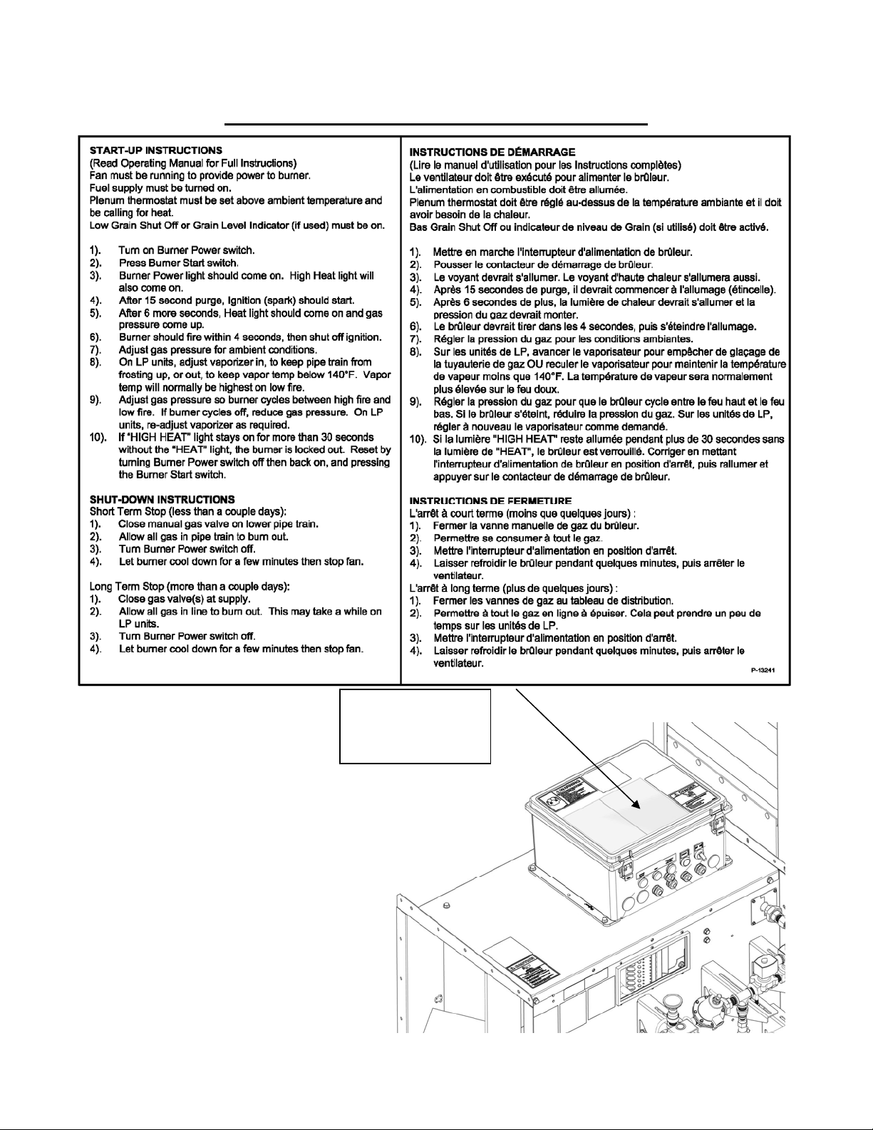
LOCATION OF OTHER DECALS ON HEATER
P-13241 (QTY 1)
DECAL, START-UP
INSTRUCTIONS
ENGLISH/FRENCH

15
LOCATION OF OTHER DECALS ON HEATER
LOCATION OF OTHER DECALS ON FAN
P-8875 (QTY 1)
DECAL, DIRECTION
OF ROTATION, CCW
P-13227 (QTY 1)
DECAL,
VAPORIZER HI-
LIMIT (LP ONLY)

16
IDENTIFICATION OF PARTS
Refer to other installed equipment manuals for a complete understanding of the total
drying and grain handling system.
FAN
118X-001A, 118Y-001A, OR 118Z-001A (15 HP)
118AA-001A OR 118AB-001A (20 HP)
LIFT BRACKET
689-091P (15 HP
AND 20HP)
MOTOR, 15 HP 3
PHASE
M-5387 (118X-001A)
MOTOR, 15 HP
1 PHASE
M-5411 (118Y-001A)
MOTOR, 15 HP 3
PHASE, 575V
M-5422 (118Z-001A)
MOTOR, 20 HP 3
PHASE, 230/460V
M-5423 (118AA-001A)
MOTOR, 20 HP 3
PHASE, 575V
M-5424 (118AB-001A)
TOP MOUNT,
CONTROL BOX
119-282P (15 HP
AND 20 HP)
BOTTOM MOUNT,
CONTROL BOX
119-283P (15 HP)
or
CONTROL BOTTOM
SUPPORT
119-296P (20 HP)
FAN GRILL GUARD
118-153W (15 HP)
FAN GRILL GUARD
118-172W (20 HP)

17
Identification of parts, con’t:
FAN FREQUENCY DRIVE CONTROL (if used)
E-6617
15 Hp, 1 Phase Input

18
Identification of parts, con’t:
LIQUID PROPANE HEATER
MANUAL GAS
VALVE, 3/8”
(
H-2956
)
NOT SHOWN:
69-220A – IGNITION WIRE, 37”
119-233P – VAPORIZER
E-6273 – IGNITION PLUG, SIDE
WIRE (For LP)
119-276A – 20” STRAIGHT
BURNER ASSEMBLY, LP
CONTROL BOX
LIQUID FILLED
PRESSURE GAUGE
30 PSI (H-2618)
SOLENOID VALVE W/
ORIFICE (691-081A)
SOLENOID VALVE
ASSY. (691-090A)
STRAINER
(H-2810)
LIQUID SOLENOID
VALVE ASSY.
(691-084A)
1/2” LP HOSE (H-1304)
VAPOR TEMP.
THERMOMETER
(H-2646)
VAPOR HIGH LIMIT OPEN
AT 120 DEG., AUTO RESET
(E-6564)
PRESSURE REGULATOR
(H-1209)
3/8” LP HOSE
(H-1306)
SAFETY VALVE
50 PSI (H-2929)
PIPE AWAY ADAPTER
(H-2880)
(FIELD INSTALLED)
RELIEF VALVE
375 PSI (H-2957) (QTY 3)
PIPE AWAY ADAPTER
(H-2879) (QTY 3)
KNOB, 3 ARM
(H-2635) (QTY 2)

19
Identification of parts, con’t:
NATURAL GAS HEATER
NOT SHOWN:
69-220A – IGNITION WIRE, 37”
E-6701 – IGNITION PLUG,
SHORT REACH (For NG)
119-291P – SPACER RING
119-300A – 20” STRAIGHT
BURNER ASSEMBLY, NG
MANUAL
REGULATING
GAS VALVE, 3/4”
(H-3126)
RELIEF VALVE
26 PSI (H-3057)
PIPE AWAY ADAPTER
(H-2880)
CONTROL BOX
SILICONE FILLED
PRESSURE GAUGE
10 PSI (H-3127)
WITH
VENT PLUG (H-3130)
3/4” SOLENOID
VALVE W/ ORIFICE
(119-288A)
3/4” SOLENOID
VALVE W/ TEST
PORTS (E-6693)
Y STRAINER
(H-3125)

20
Identification of parts, con’t:
BLUE FLAME II CONTROL BOX, CSA
119-278A 15HP LP, 119-292A 15 HP NG
119-294A 20HP LP, 119-295A 20HP NG
RELAY (E-5764)
RELAY SPRING
(E-6068)
RELAY SOCKET
(E-6069)
LIGHT AND LIGHT
LENS, C22
(E-6622, E-6623) (3)
TERMINAL BLOCK
4 COND. WAGO
(E-6368) (14)
DECAL, 1-14
(P-13237)
TERMINAL END
PLATE W/ FLANGE
(E-6367)
PUSHBUTTON
SWITCH, START,
1NO
(E- 6624)
(E-6625)
SWITCH TOGGLE,
OFF/ON, 6 AMP
(E- 6557)
(E-6558)
GROUND BAR KIT
(E-6289)
FUSE
HOLDER
(E-6556)
DIN RAIL
(E-6568)
FUSE , 5 AMP
SLO-BLO
(E-5267) (2)
BURNER HIGH-LIMIT
220 DEG. F, MANUAL
RESET
(E-5133)
FENWAL HARNESS
(691-091A)
FENWAL FLAME
SENSE MODULE
(E-6569)
FLAME ROD ASSY.
(119-261A)
IGNITION
TRANSFORMER 120
VAC PRIMARY 6000
VOLTS SEC.
(E-6195)
AIR FLOW SWITCH
ASSEMBLY
(119-279A, 0.75”
W.C.)(15 Hp)
Or
(119-293A, 1.5”
W.C.)(20 Hp)
This manual suits for next models
15
Table of contents
Popular Dryer manuals by other brands


Beko
Beko B5T692343WBPB user manual

LG
LG Steam Dryer DLEX7177SM User's guide & installation instructions

Hotpoint
Hotpoint TCEL 87C Instruction booklet

Pneumatech
Pneumatech PE Series owner's manual

Ingersoll-Rand
Ingersoll-Rand TS1A Operation and maintenance manual

Ingersoll-Rand
Ingersoll-Rand D127NC Operator's manual