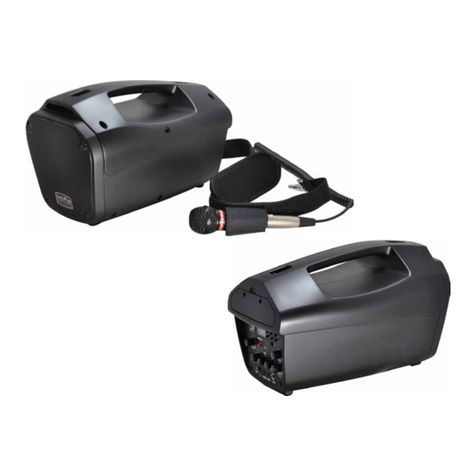
Show PSA Series User manual

R
www.show-pa.com
User's Manual
c
SEIKAKU TECHNICAL GROUP LIMITED
No.1, Lane 17, Sec. 2, Han Shi West Road, Taichung, 401 TAIWAN
Tel:886-4-22313737 Fax:886-4-22346757
All rights reserved to SEIKAKU. All features and content might be changed
without prior notice. Any photocopy, translation, or reproduction of part of this
manual without written permission is forbidden. Copyright 2008 SEIKAKU Group
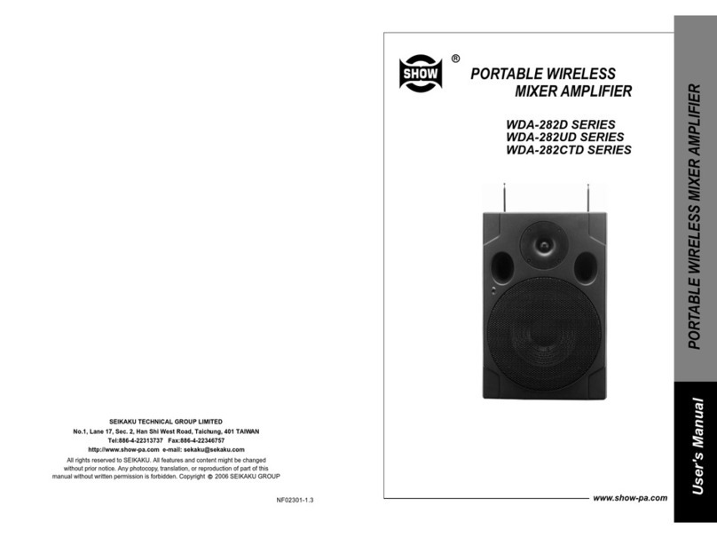
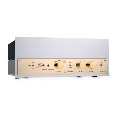
PROFESSIONAL STEREO AMPLIFIER
PSA Series
Professional Stereo Amplifiers
PSA-3600
PSA-3900
PSA-31500

IMPORTANT!
Please read this manual carefully before operating
this unit for the first time.
All rights reserved to SHOW. All features and content might be changed
without prior notice. Any photocopy, translation, or reproduction of part of
this manual without written permission is forbidden.
-10-
ELECTRICAL SPECIFICATIONS
INPUT SENSITIVITY
INPUT IMPEDANCE
FREQUENCY RESPONSE
(@10dB below rated output
power)
VOLTAGE GAIN
DISTORTION(SMPTE-1M)
S/N Ratio
Full short circuit, open circuit, thermal, ultrasonic, and RF protection
stable into reactive or mismatched loads, turn ON/OFF, muting, tried
crowbar
GENERAL SPECIFICATIONS
PROTECTIONS
1.15 V (+3.4 dBu)
10 K Unbalanced 20 K Balanced
25 Hz~25 KHz +0/-1 dB
-3 dB points: 5 Hz~50 KHz
28 dB
<0.03%
100 dB
32dB 34 dB
4 Ohms (RMS)
4 Ohms (EIAJ)
2 Ohms (EIAJ)
8 Ohms (RMS)
8 Ohms (RMS)
POWER SPECIFICATIONS
750 W 2x
350 W x 2
230 W x 2
710 W
1500 W
PSA-3600
Stereo Mode
(Both channels driven)
20Hz~20KHz
Bridge Mono Mode
20Hz~20kHz
CONTROLS
INDICATORS
CONNECTORS
POWER SUPPLY
DIMENSIONS
WEIGHT
Front: AC switch, Input level control for each channel
Rear: stereo/ parallel/ bridged selector, 30Hz filter selector clip
ON/OFF selector.
INPUT : Active balanced XLR and 1/4"(6.3 mm)TRS
OUTPUT: "Touch-proof" binding posts and speak-on jacks.
Available for 110-120 V or 220~240 V AC, 50/60 Hz
483(W) 460(D) 88.8(H)mm
14.5 kg 17.3 kg 20.7 kg
SIGNAL: 2 green LED CLIP: 2 red LED
POWER: 1 Green LED
1000 W
510 W
285 W
1000 W
2200 W
PSA-3900
1800 W
900 W
560 W
1800 W
3100 W
PSA-31500
9. TECHNICAL SPECIFICATIONS

INPUT
LINK
E.R 30Hz-9dB LA DIF PWR AMP OUTPUT
CH-A
CH-A
1.15VRMS
+4dB
15Kohm
BALANCED
SUB WOOFER
(OPTION)
+/-
MODE
INPUT
LINK
E.B LA DIF PWR AMP OUTPUT
CH-B
CH-B
AUTORAMP
TURN-ON CIRCUIT SHOCK
DC OFFSET
DC SERVO
OVER TEMP
SHORTCIRCUIT
CURRENT LIMITER
TURN-ON/TURN-OFF
TRANSIENTS
BRIDGED
PARALLEL
MONO
ACTIVE
CLIP
CH-A
CH-B
AMP
SIG
CH-A
CH-B
OPTION
BINDING POST
TERMINALS
AC PWR
DETECTOR
POWER TRANS
CH-A
CH-B
PROT&PRE
PWR
INDR
2-SPEED FANS
IN-RUSH
CURRENT
POWER
SWITCH
CIRCUIT
BREAKER
AC POWER
120V/220V/230V
/240V 50/60Hz
(OPTION)
:XLR CONNECTOR
:1/4" PHONE JACK
:SPEAKON CONNECTOR
NOTICE
30Hz-9dB
8. BLOCK DIAGRAM
-9-
SAFETY RELATED SYMBOLS
The symbol is used to indicate that
some hazardous live terminals are
involved within this apparatus, even
under the normal operating conditions.
The symbol is used in the service
documentation to indicate that specific
component shall be only replaced by
the component specified in that
Documentation for safety reasons.
Protective grounding terminal.
Alternating current /voltage.
ON: Denotes the apparatus turns on.
OFF: Denotes the apparatus turns off,
because of using the single pole switch,
be sure to unplug the AC power to prevent
any electric shock before you proceed your
service.
WARNING: Describes precautions that
should be observed to prevent the danger
of injury or death to the user.
CAUTION: Describes precautions that
should be observed to prevent danger of the
apparatus.
WARNING
Power Supply
Ensure the source voltage matches the
voltage of the power supply before turning
ON the apparatus.
Unplug this apparatus during
lightning storms or when unused for
long periods of time.
External Connection
The external wiring connected to the
output hazardous live terminals requires
installation by an instructed person, or
the use of ready made leads or cords.
Do not Remove any Cover
There are maybe some areas with
high voltages inside, to reduce the risk
of electric shock, do not remove any
cover if the power supply is connected.
The cover should be removed by the
qualified personnel only.
No user serviceable parts inside.
Fuse
To prevent a fire, make sure to use fuses
with specified standard(current,voltage,
type). Do not use a different fuse or short
circuit the fuse holder.
Before replacing the fuse, turn OFF
the apparatus and disconnected the
power source.
Protective Grounding
Never cut off the internal or external pro-
tective grounding wire or disconnect the
wiring of protective grounding terminal.
Hazardous live terminal .
Disposing of this product should
not be placed in municipal waste
and should be separate collection.
Before turning the product ON, make sure
that it is connected to Ground. This is to
prevent the risk of electric shock. Never
cut internal or external Ground wires.
Likewise, never remove Ground wiring
from the Protective Ground Terminal.
The apparatus shall be connected to a
mains socket outlet with a protective
earthing connection.

Operate PSA Professional Stereo Amplifiers Bridged Mode
In this mode, the channel A input signal will be output from the bridge output
Connectors (The 2 RED binding post). In this case, use the channel A volume
control to adjust the volume, keep the volume control of channel B turned completely
down (counterclockwise ). Bridged mode is intended for driving loads with a total
impedance of 4 ohms or greater. In Bridge Mode you will combine the power of
both channels into one speaker. You will have available massive amount of power
so check carefully the power handling of your speaker before operation.
Input wiring tips
BALANCED UNBALANCED
PARALLEL
(MONO)
NO USING
STEREO
BRIDGED
1
2
3
GND
INPUT FROM
SOURCE
1
2
3
INPUT FROM
SOURCE
SHIELD
+ +
SHIELD SHIELD
channel A
channel B+
+
NO USING
channel A+
+
channel 2+
channel 1+
-8-
ventilation openings.
youarequalifiedtodoso.
normally, or has been dropped.
Servicing
Refer all servicing to qualified personnel.
To reduce the risk of electric shock, do not
perform any servicing other than that
contained in the operating instructions unless
Servicing is required when the apparatus has
been damaged in any way , such as power
supply cord or plug is damaged , liquid has
been spilled or objects have fallen into the
apparatus, the apparatus has been exposed
to rain or moisture , does not operate
To reduce the risk of fire or electric
shock, do not expose this apparatus
to rain or moisture.
Do not use this apparatus near water.
Install in accordance with the manufa
-cturer's instructions. Do not install
near any heat sources such as
radiators, heat registers, stoves, or
other apparatus (including amplifiers)
that produce heat. Do not block any
IMPORTANT SAFETY INSTRUCTIONS
Read these instructions.
Keep these instructions.
Heed all warnings.
Only use attachments/accessories
specified by the manufacturer.
Power Cord and Plug
Do not defeat the safety purpose of
the polarized or grounding type plug.
A polarized plug has two blades with
one wider than the other. A grounding
type plug has two blades and a third
grounding prong. The wide blade or the
third prong are provided for your safety.
If the provided plug does not fit into
your outlet,consult an electrician for
replacement of the obsolete outlet.
Protect the power cord from being walk-
ed on or pinched particularly at plugs,
convenience receptacles, and the point
where they exit from the apparatus.
Follow all instructions.
No naked flame sources,such as lighted
candles, should be placed on the
apparatus.
Cleaning
When the apparatus needs a cleaning, you
can blow off dust from the apparatus with
ablowerorcleanwithragetc.
Don't use solvents such as benzol, alcohol,
or other fluids with very strong volatility and
flammability for cleaning the apparatus body.
Clean only with dry cloth.
The mains plug is used as the disconnect
device,the disconnect device shall
remain readily operable.
Operating Conditions
This apparatus shall not be exposed to
dripping or splashing and that no
objects filled with liquids, such as
vases, shall be placed on this apparatus.
12
3
BRIDGED INPUT
CH-B
LINE
BALANCED
INPUT
LINE
CH-A
CLIP LIMT
OFF ON
BRIDGED
STEREO
PARALLEL
(MONO)
OFF ON
LF 30HZ
FILTER
1.15V/20K
INPUT
CONNECTION
(+)
-
()
(GND)
SRT
T(+)
S(GND)
R( )
-
CH-A CH-B
BRIDGED
MONO
CHANNELA CHANNEL B
BREAKER
SERIAL
MODEL
CHA
1+
1+
1+
1
+
2
BRIDGEDBRIDGED
CHB
1
21
3
PUSH
21
3
PUSH
1. INTRODUCTION...............................................................................1
2. FEATURES........................................................................................1
3. PREPARATION BEFORE STARING.................................................1
4. CONTROL ELEMENTS.....................................................................2
5. WIRING CONFIGURATION..............................................................4
6. CONNECTION FOR INPUT SIGNAL...............................................5
7. INSTALLATION AND CONNECTION................................................6
8. BLOCK DIAGRAM............................................................................9
9. TECHNICAL SPECIFICATIONS.....................................................10
TABLE OF CONTENTS
-7-
Operate PSA Professional Stereo Amplifiers in Parallel Mode
In this mode, the channel A input signal will be output from the output connectors of
both channels. The channel B input jack is not used; the channel A and channel B
volumes can be adjusted independently. Use the parallel mode when you want to drive
two speakers with only one input signal keeping separate control of the volume of the
two channels.
NOTE: since you are not using the channel B input you can use this socket to "daisy
chain" the signal to another amplifier.
Input wiring tips
BALANCED UNBALANCED
1
2
3
GND
INPUT FROM
SOURCE
1
2
3
INPUT FROM
SOURCE
SHIELD
+ +
SHIELD SHIELD
PARALLEL
(MONO)
STEREO
NO USING
BRIDGED
+
+
channel B
channel A
channel A

2. FEATURES
Clip-limiter circuit that is user-adjustable
Switchable low-frequency filter at 30Hz
Operating mode are stereo, parallel or bridge
Balanced XLR and 1/4" TRS input connectors
Output connectors are speakon jacks and binding post terminals
Low-noise, variable speed fan
Front panel LED indicating signal and clipping and protection status
Manufactured under QS9000, VDA6.1 certified management system
3. PREPARATION BEFORE STARTING
Check the AC voltage used in your country. Proper grounding prevents user from
electric shock
Before switching on the power, make sure gains are turned to minimum to prevent
damaging other equipments
Check your cables regularly and label each end clearly for easy identification
Always turn off the power before connecting or disconnecting the unit
NEVER use solvents to clean the unit. Clean it with a soft and damp or dry cloth
1. INTRODUCTION
Thank you for purchasing one of our PSA Series Professional Stereo Amplifiers. The
PSA Series includes PSA-3600, PSA-3900, PSA-31500. All models are rugged, 2
rack-unit professional stereo amplifiers fan-cooled. Despite their compact dimensions
they provide a lot of power and a high value performance. They are all designed for
heavy-duty application and they all can drive 2 ohm loads for long periods without
overheating. Therefore they are suited to drive subwoofers with a minimum load of
-1-
The PSA Professional Stereo Amplifiers provide three operating modes: stereo mode,
parallel (mono) mode and bridged mode, you can decide each specific operating mode
according to your actual application circumstance.
Operate PSA Professional Stereo Amplifiers in Stereo Mode
In this mode, channel A and channel B operate independently (as a conventional
stereo amplifier). The channel 1 input signal will be output from the channel A output
connectors, and the channel B input signal will be output from the channel B output
connectors.
Input wiring tips
BALANCED UNBALANCED
1
2
3
GND
INPUT FROM
SOURCE
1
2
3
INPUT FROM
SOURCE
SHIELD
+ +
SHIELD SHIELD
+
channel A
+
PARALLEL
(MONO)
STEREO
BRIDGED
channel B
channel A
channel B
7. INSTALLATION AND CONNECTION
-6-
12
3
BRIDGED INPUT
CH-B
LINE
BALANCED
INPUT
LINE
CH-A
CLIP LIMT
OFF ON
BRIDGED
STEREO
PARALLEL
(MONO)
OFF ON
LF 30HZ
FILTER
1.15V/20K
INPUT
CONNECTION
(+)
-
()
(GND)
SRT
T(+)
S(GND)
R( )
-
CH-A CH-B
BRIDGED
MONO
CHANNELA CHANNEL B
BREAKER
SERIAL
MODEL
CHA
1+
1+
1+
1
+
2
BRIDGED
CHB
1
21
3
PUSH
21
3
PUSH
4 ohms when working in Bridge Mode.

4. CONTROL ELEMENTS
Power Switch
It powers the PSA Professional Stereo Amplifier ON and OFF.
Power LED
This power LED lights up when the unit is powered up.
Clip LEDs
These LEDs will light up when distortion reaches a level of 0.5%, turn the relative
gain control down so that the clip LEDs only flash occasionally. And these LEDs
will light up when the unit is in protection mode due to overheating, exist DC output
or other causes.
Signal LEDs
These LEDs will light up when the signal at the output is at least 100 mV.
Gain Controls
These controls are used to adjust the output signal level. In stereo mode, they
are used to control the level of respective channel; In bridge mode, only the gain
control of channel A is used to control the volume of the whole system.
1
2
3
4
6
Front Panel
-2-
Rear Panel
7
61012
914
118
13
Connect input signal to mix balanced MIC input socket: balanced input (6-1),
unbalanced input (6-2). It is suggested to use the balanced input especially
when the audio cable is very long, this will effectively reduce "hum" noise
caused by AC power.
6. CONNECTION FOR INPUT SIGNAL
Pin1( )
Pin2 (+)Pin3 (-)
GROUND
HOT (+)
COLD ( )
3
2
1
-5-
GND
(-) Input
(+) Input
(+) Input
(-) Input
GND
Fig. (6-1) Balanced input
(+) Input
GND GND
(+) Input
Fig. (6-2) Unbalanced input
12
3
BRIDGED INPUT
CH-B
LINE
BALANCED
INPUT
LINE
CH-A
CLIP LIMT
OFF ON
BRIDGED
STEREO
PARALLEL
(MONO)
OFF ON
LF 30HZ
FILTER
1.15V/20K
INPUT
CONNECTION
(+)
-
()
(GND)
SRT
T(+)
S(GND)
R( )
-
CH-A CH-B
BRIDGED
MONO
CHANNEL A CHANNELB
BREAKER
SERIAL
MODEL
CHA
1+
1+
1+
1
+
2
BRIDGEDBRIDGED
CHB
1
21
3
PUSH
21
3
PUSH
In normal operation, the Led will not illume; If the Led is red, it means the unit is in
heat protection, no sound is output. The speaker system is actually disconnected
from the amplifier outputs when this LED is red, the temperature must be lowered
by better ventilation and decrease the signal level etc. if the problem is corrected,
the protection systems deactivate automatically, and normal amplifier operation is
resumed.
1 2
4
3
5
6 6
5
4Protection LEDs

Low Frequency Filter
This filter rolls off audio signals below 30 Hz. In this way bass performance will be
improved, because the subsonic motion of the cone will be cut out and more power
is made available to the woofer in the audible range of frequencies. If you want our
view: keep the filter on most of the time unless you are filtering the signal before the
input of the amplifier. Especially vented speakers (bass-reflex) are very sensitive to
subsonic frequencies (below 30 Hz).
12
Circuit Breaker
This is an electronic fuse for protecting the unit from possible damage. When the unit
is overloaded or the temperature inside the unit is too high, this push-type button will
spring out and disconnect the power supply. Push the breaker to restore normal
working conditions.
IEC Socket for AC Power Cable
Connect the supplied main cord. Do not insert the power cord into the amplifier and
into the AC outlet until voltage has been correctly set.
XLR Balanced Input Connectors
Each channel features balanced XLR and 1/4" jack sockets wired in parallel. The
balanced signals are less sensitive to hum noise generated by AC.
Speakon Outputs (channel A & channel B)
These connectors are specifically designed to connect high power speakers. The
correct polarity is secured automatically, they prevent shock hazard and they lock-in
securely.
Binding Post Outputs (channel A & channel B)
Please make sure to respect the speaker polarity when using binding post.
urn off the unit before connecting an audio signal to the binding post toCaution: T
avoid any electric shock!
6
7
8
9
10
Clip-limiter switch
If a very high level signal is driven into the amplifier, the output signal will clip, that
the peaks of the waveform will be flattered. The clip limiter circuit automatically
reduces the gain to prevent the overdrive. You can switch the clip limiter circuit on
and off via the switch on the rear panel of your amplifier. If you use full range speakers,
the clip limiter circuit will reduce the high frequency distortion and it will also protect
the high frequency drivers. However, some users prefer to switch the limiter off to
get more punch from kick drums and other sounds in the low frequencies area.
11
-3- -4-
5. WIRING CONFIGURATION
- Parallel Mono Mode
In this mode, channel A input signal will be output from the output connectors
of both channels.
- Bridged Mode
In this mode, channel A input signal will be output from the bridge-mono output
connector.
Output Mode Selector
The PSA series professional stereo amplifiers present three operating modes:
- Stereo Mode
In this mode, channel A and channel B operate independently (as a normal stereo
amplifier). The channel A input signal will be output from the channel A output
connector, and channel B input signal will be output from the channel B output
connector.
14
Cooling Fan
This fan secures enough cooling for your amplifier. The airflow is front-to-rear.
The fan speed is electronically regulated depending on the temperature of the
power devices.
13
1
2
3
1
2
3
12
3
21
3
Tip
Sleeve
1
2
3
TIP SLEEVE
12
3
Tip
Ring
Sleeve
1
2
3
TIP RING SLEEVE
12
3
Tip
Sleeve
Tip
Sleeve
TIP SLEEVE SLEEVE TIP
Tip
Ring
Sleeve
Tip
Ring
Sleeve
TIP RING SLEEVE SLEEVE RING TIP
Tip
Ring
Sleeve
1
2
3
TIP RING SLEEVE
12
3
1
2
3
1
2
3
21
3
12
3
Tip
Ring
Sleeve
Tip
Ring
Sleeve
TIP RING SLEEVE SLEEVE RING TIP
Unbalanced Input
Balanced Input
This manual suits for next models
3
Table of contents
Other Show Amplifier manuals
