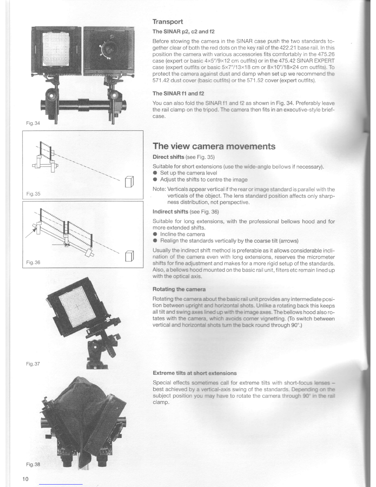
Sinar p2 User manual

lnstruction
Manual

iT
The
cameras
Operating
controls
oftheSINAR
p2andc2
1 Coarse-focus
clampinglever
2 Finefocusing
drive
with
depth
offield
scale
3 Micrometer
driveforvertical(rise
andfall)
shift
4 Micrometer
drivefor lateral
(cross)
shift
5 Micrometer
drive
forhorizontal-axis
tilts
6 Micrometer
drive
for vertical-axis
swings
7 lmage
plane
mark
8 Coarse-tilt (horizontalaxis) clamping lever;
movement
usedfor vertical
alignment
of stan-
dards
with
camerainclined
upordown,
alsofor
coarse
tilting
to reserve
full micrometer
tilt (5)
range
forsharpness
distribution
control.
Fig.1
Contents The cameras 2
- Controls 2
- Zerosettings 3
- Mounting
thecamera 4
- The
spiritlevels 4
- The baserail 4
- Changing
components 4
- The
bellows 5
- Camerabacks s
- Switching
formats
ontheSTNAR
p2 and
c2 6
- Switchingformats
ontheSINARf2 andtl g
- The
convertible
camera g
- The
bellows
hood 9
- Viewing
aids 9
- Transport l0
Theview cameramovements 10
The
plane
ofsharpness
anddepth
offield 11
Fufiher accessories
- SINAR
COLOR
CONTROLfitters
- Exposure
meters
- Automatic
SINARfilmholder
andshutter
coupling
- Film
holders
Finalpoints
- Maintenance
- Cleaning
- Adjustingthe drives
- Cleaning
lenses,
filters
andmirrors
- Warranty
- Further
instruction
manuals
12
12
12
12
13
14
14
14
14
14
14
14
Remark: The
camera
c2 isno longer
part
oftheSINAR
sales
programme,
butcanstiltr
becombined
bytheindividual
SINAR
components.

Operating
controls
ofthe
S|NAR
t2andtl
1 Coarse-focus
clamping
knob
2 Finefocussing
drive
with
depth
offield
scale
3 Clampingwheelfor
vertical
shift
4 Clampingleverforlateral
shift
5 Clampinglever
for
swing
(vertical
axis)
6 Clamping
leverfor
tilt
(horizontal
axis)
7 Angle-metering
scalefortilt
and
swing
angles
8 lmage
plane
mark
Zero setting points of the cameras
CAMERAMODELS REAR
(IMAGE)
STANDARD FRONT
(LENS)
STANDARD NOTES
SINARo2
Withregular
orspecial 4x5 / gxi|2
standard
bearer 5x7 /13x18
WithF/Sback Bxl)/18x24
With
metering
back Bxl}/18x24
White l
Green i dots
Red )
Red rings j or.
nngs
White
White
Red.
Red
- Whitedotfor
lateral
shifton
speciallens
standard
SINAR
c2
Withregular
standard 4xS / 9x12
bearer 5x7 /13x18
With
F/Sback Bxl)/18x24
With
metering
back Bxj0/18x24
With
specialstandard 4xS/ 9x12
bearer Sx7 /13xj8
WithF/S
back Bxl}/18x24
With
metering
back Bxl)/18x24 ] o,
"o*"
White
Green
Red
Red ] o*.
nngs
2nd
vert,
eng.
stop
2ndvertical
engagement
stop
3rdvert.
eng.
stop
lI As
above
)
I Lens
standard
I atzero
point
J for lateral
shift
White
dot for lateral
shift
(at
32.5mm)
I Lens
standard
l atzero
point
J for lateial
shift
SINAR
f2 4xS/ 9x12
With4x5"/9x12
cm
lens
standard Sx7 /13x19
8x1O/18x24
4x5"
f2standard:
'1st
(lowest)
vert.
eng.stop
5xT"
standard:
lowest
position
8x10"
standard:
lowest
position
4x5"f2standard:
1st
(lowest)
verl.
eng.stop
2ndvert.
eng.stop
4th
(top)
vert.
eng.stop
SINARf2 5x7 /13x18
With
speciallens
standard 8x1o/18x24
5x7"f2
standard:
lowest
position
Bxl0"
standard:
lowest
position
8x1
0"
f2special
stand.:
1st
(lowest)
vert.
eng.
stop
3rd(top)
vert.
eng.stop
SlNARfl 4x5 / 9x12 4x5"
f2stand.:
1
st
(lowest)
vertical
engagement
stop Multipurpose
stand.:
1
st
(lowest)
vert.
eng.
stop

Fig.5
Fig.6
Fig.7
Mounting
thecamera
Withthe 411.21
rail
clampor 411.41railclampfor higher
stability
youcan
mount
the
SINARcameras
eitheronthe
516.41
pan
tilthead
ordirectlvona
triood.
O Turntheclampinglever
A againstthearrowto release
it,fitthecamera
andtighten
thetripod
screwCfinger
tight.
O Turnthe clampinglever
A in the directionof the arrowto securetne
camera
firmly.
O To
adjusttheleverA useacointo unscrew
the
centrescrew.Remove
tne
lever
andrefitintherequired
position.
Replace
thesecuringscrew.
O SlackofftheknobB bya fewturnsto shiftthecamera
alongtherailfor
balancing
orto swivelitaboutthe rail.
Slackoff bv afewturnsmorero
remove
thecamera
altogether.
Therail
clamp
alsotakesthe519.11universal
cameraholder
for mountinq
35mmandrollfilm
reflex
cameras.
Zero
setting
Before
starting
operations
set all movements
to their zero engagement
points.
Q marksthe
image
plane.
The
spiritlevels
Toread
the
spiritlevels
precisely,
viewwith
one
eyecentred
abovethem.
you
seethem
correctly
when
eachmarking
ring
appears
truly
edge-onasathin
line.
lf
thelevels
should
eventuallyneed
resetting,
you
candothis
yourself.
Slack
offone
screw
completely
andthesecondone
slighfly,realign
the
spiritlevel
and
tighten
thescrewsagain.
Thebaserail
Thecamera
outfitincludes
a 12"/30
cm 422.21
baserail,
capped
at both
ends
andsuitable
for
allSINAR
cameras.Rail
extensions
screw
toeither
end
tomake
upanyrequired
length.
A longer
36'790cm 425.21
baserailis
avail-
ableforconstant
usewithlong
extensions.
Ghanging
components
When
switching
metering
backs,bellows,
lens
boards,
etconthecoupling
frame,
always
push
insuchitems
straightfrom
above
andlock.To
avoidlight
leaks
besureto closethelocking
lever
fully.
But
don'tuseforceif
thelever
ishardto close
- check
rather
thatthe
component
is
correcilyfitted.
Fg8q
+
Fig.9

Whenfittinglenses
lineupthereddot attherear
ofthelens
board
withthe
red dot on the behind-lens
shutter.
Insert
the lensboard and lock.The
aperturecontrolsthencouple
automatically.
Lensboardholder
Itisrecommended
to mount
the531.41lensboard
holder.
The
bellows
Folding
bellows
Thefolding
bellows
shouldnever
sag
- sodo notplace
anything
ontop of
them.Also,to counteract
sagging,
periodically
refitthe bellows
inverteo
about
theiraxis.
The
wide-anglebellows
To
permit
infinity
focusing
with
shortcamera
extensions
pull
anyfolds
of
the
wide-angle
bellows1fully
outfrom
between
thecamera
standards.
Usethe455.46
wide-angle
bellows
2for
4x5"/'1
9x12cmpictures
with
65mm
lenses
andvery
short
extensions.
Gamera
backs
The
sINARmodels
p2,
c2 and
f2include
ametering
backwith
probe
holder
(462.16tor
4x5"/9x12
cm,462.17
tor
5x7"/13x18
cmand 462.S1for
8x10,7
''|8x24
cm).
The461
.36
backofthe4x5"/9x12
cmSINAR
f1has
nometer
probe
holder
andnoliftinglevers.
To
convertto themetering
back
replace
thefilm
holder
frame
bythe462.96
frame
with
probe
holder.
lfyou
alsowant
thelifting
lev-
ers,replace
themodel
1screen
frame
bythemodel
2,461.56.
Fitting
the backonthe camera
open thelocking
lever
atthetop left
(4x5'79x12
cm)orattheleft
andright
(5x7"/13x18
cmand8x10"/18x24
cm)
ofthe
rear
coupling
frame,
insert
the
backatthebaseofthecoupling
frame,
push
home
andlock
(also
seeFigs.
8and
9).
For
upright
and
horizontal
shots
you
canfitthebacksin
alternative
positions
turned
through
90".
(For
horizontal
shots
position
the
meter
probe
holder
atthe
top,forupright
shots
attheleft.)
Fig.10
Fig.
14
I
Fig.13

Removing
the screenframe
(4x5"/9x12
cm back)
To
separatethe
screenframefromthefilmholder
frameuse
both
thumbs
to
depressthe
serratedcouplinglevers
attheleft
and
right
while
pushing
the
screenframe
upwards
(see
Fig.15).The
"Graflock"
typelatchesatthe
sides
ofthefilmholder
frame
permit
directattachment
ofbulkyrollfilmholders.
Toreassemble,
fitthescreenframe
shiftedupwardsthrough
about
1
cm(so
thattheholes
at
the
sidesarelevel)
and
push
downtillit
engages.
lnserting
film holders
Themetering
backhasliftinglevers
atthe bottomleftand rightto liftthe
screenframe
offthefilmholderframe.
Thislifting
systemfacilitates
smooth
insertion
offilmholders.
Forthinfilmholders
slightly
depress
one
lever,
push
in
theholder
and
let
go.
Forthickerholders
fully
openbothlevers,
push
in
the
filmholder
and
close
thelevers.
Ona back
withoutlifting
leverslifithe
screenframe
asshowninFig.18
and
push
inthe
filmholder.
Switching
formatsontheSINAR
p2 andc2
Release
thebellows
atthelens
end.Releasetherear
couplingframe
byturn-
ing
theknobF
anticlockwise.
Youonly
changetheformat
set,consisting
of
the rear
coupling
frame,
bellowsandback.Setthestandards
to theirzero
positions
- colour-codedwith engagement
stops(see
tableon page3)-
before
switchingformats.
TheSINAR
p2specialfront standard
The zero settingson this standard
are speciallylocatedfor the 8x1O"/
18x24
cmformat
to make
best
useoftheshiftranges.
Usealsothe
special
rear
standardbearerwith
thespecialfront
standard.
TheSINAR
p2undc2 specialrearstandardbearer
This heavy-duty
standard bearer,specifically
designedfor the 8x1O"/
18x24cm format,forms
thebottom
sectionoftheSINAR
p2 andc2 rear
standard.lt makes
bestuseofall
shift,
tiltandswingrangesand
alsohasa
deoth
offield
scale.
Fis.19

Themultipurpose
standard
Thisserves
as
thelens
standard
ontheSINARf1
.ltcanalso
beused
asan
object
stage
for
close-ups
andmacro
shots
andas
an
intermediate
standard
forlong
cameraextensions.
Setthevertical
andlateral
shifts
tothe
appropriate
engagement
stop
orcol-
oured
mark
(see
table
onpage
3)to match
thelocation
ofthe
optical
axisto
theformat
combination
used.
Raising: Slack
offthe
clamping
screw
and
push
upthe
columns
asshown
inFig.
21.
Lowering:
SeeFig.22.
Fitting/removal:
Fully
unscrewthe
coarse-focus
clamping
screw
toopenthehinged
collarof
themultipurpose
standard.You
can
thenremove
thestandard
without
dis-
mantlingthe
camera.
You
canalsoreset
the clamping
levers
ofthe multipurpose
standard.
Un-
screwthe retaining
screwwitha coin,remove
thelever
andrefitin
there-
quiredposition.

L
r26d
Switchingformats onthe SINAR
f2 andfl
Release
thebellowsatthelensendandremovetogetherwiththewhole
rear
standard
(the
coupling
frameisherefixedtoits
standardbearer).Now
fit
the
required
alternativerearstandard
(5x7'713x18
cmor8x10'7'18x24cm)
with
itsmatchingtaperedbellowsintheusualway.Formatchangingisthussim-
ple
andrapid.The
basicdesignoftherear
standard
isthesame
forall
three
formatsbutthetwolargersizesarereinforcedandtheopticalaxisisrecen-
tered.
Operation
isthesameaswiththe4x5"/9x12
cm rearstandard.
The
rear
standardleftoverafterswitchingformatsremains
partof theSINAR
system
toserveasanauxiliaryorintermediatestandard.
TheSINARf2 specialfront standard
For
the5x7"
/13x18cmandthe8x10'7'l8x24cmversions
ofthecamerawe
recommend
the431.62
SINARf2specialfront
standard.lt provides
alarger
shiftrange
asitszero
positions
arespecially
alignedfortheselargerformats.
Theheavy-duty
construction
isalsomorerigid.
Thisspeciallens
standardis
partofthe 5x7"
/13x18 cm andthe 8x10,718
x24cm SINARf2outfit.
Theconvertiblecamera
TheSINARf2 istheentry
point
to theversatile
SINARsystemwithitsfully
compatible
components.Asrequirements
becomemore
ambitious,chang-
ing
therear
standardconvertsthef2
totheSINAR
c2.
lf
you
then
replacethe
lens
standard
bythat
of
the
p2,you
have
acompleteSINAR
p2.
All
elements
otherthan
thealternative
camerastandardsremain
thesame.
Components
left
overhavefurther
applicationsinthe
SINARsystem.With
just
afewaddi-
tional
partsyou
canevenusethemtoassembleasecond
camera.
Fig.26e

The
bellows
hood
The SINAR
universar
beilows,
two beilows
horders
and a betows rod or
jointed
rod
form
the
simpre
rens
hood.
srNAR
accessories
can
arso
make
up
a professionar
beilows
h.ood,
consisting
ofthebeilows
hoodmask
10r2,a
bellows
rod,
beilows
horder,
murtipurpose
standard
anduniversar
beilows.
Thebetowshoodmask
2 has
four
micrometer-adjustabre
roterbrinds
with
mm
scales
for
precise
masking.
Topermit
unobstructed
shifts
withshort
extensions
oo notattach
theber_
lows
to
the
lens.
Indirect
shifts
arepreferabre
with
theprofessionar
beilows
hood
_ which
rs
more
frequenily
used
with
long
extensions.
For
aclear
view
ofthehoodlimits,
to avoid
image
vignetting,
stopdown
to
theworking
aperture
and
sight
through
thecutiway corners
oftheground
glass
screen,
with
the
eye
close
tothä
screen.
Viewingaids
Fresnel
screens
with.aFresner
screenyoumore
easiry
take
in
the
whore
screen
image
- and
see
itbrighter
and
withbetter
contrait.Fresner
screens
are
avairabre
forarl
threesrNARback sizes.
Thegroundgrass
screen
frames
have
retaining
springs
forquick
fitting
and
removal
oftheFresnet
screen.
Thebinocularmagnifier
andbinocularreflex
magnifier
A wide-angle
oruniversar
beilows
attached
tothe
screen
frame
keeps
stray
light
offthe ground
glass
screen.
This
viewing
bellows
inturn
takes
the
binocular
magnifier
and
its
hood.
With
the
magnifiers
swung
in,
the
screen
image
appears
magnified
2x.fhe
binocular
reflex
magnifier.arso
shows
theimaleupright;
it
atLches
direcay
tothe
4x5"/9x12
cm back.
To
view
the
whore-screen
image
with
the
rarger
sizes
youalso
need
a murtipurpose
standard
andatapered
orwide-angre
bellows
behind
the
back.
pairs
of
4.2b-diopter
magnifier
renses
are
avairabre
forboth
versions
as
an
alternative
tothesiandard
3_diopter
lenses.
Masks
To,.T""fdown
theimage
on
the
ground
glass
screen
wnen
working
with
the
rollfilm
holders
we recommend
thetranJparent
ye*owmasks
ofthesg4..r6
mask
set or the s34j2 vario
mask.
Themasks
areavairabre
withcutouts
from
4'5xG
to
8.5x10.5
cm
andfit
the
srNAR
mask
and
Fresner
rroroer.
rLy
are
inserted
in,
and
removed
from,
the
screen
frame
in
the
same
way
asthe
Fresnel
screens.
Fig.30

Fig.36
Fig.37
Fig.38
{n
Transport
TheSINAR
p2,c2andt2
BeforestowingthecameraintheSINARcase
push
the
twostandardsto-
gether
clearofboththereddotsonthe
keyrail
of
the422.21
base
rail.In
this
position
thecamerawith
various
accessories
fits
comfortably
inthe475,26
case
(expert
orbasic
4x5"/9x12cmoutfits)orinthe475.42SINAREXPERT
case
(expert
outfits
or
basic5x7"/13x1Bcmor8x10"/1
8x24
cmoutfits).To
protect
thecameraagainstdustanddamp
when
setupwe
recommend
the
571.42dustcover
(basic
outfits)or
the571.52
cover
(expert
outfits).
The
Sf
NAR11
andf2
You
canalsofoldtheSINAR
t1andt2asshowninFig.34.
Preferably
leave
therailclamp
on
thetripod.The
camera
thenfitsin
anexecutive-stylebrief-
case.
The
view
cameramovements
Directshifts (see
Fig.35)
Suitablefor
shortextensions
(use
the
wide-angle
bellows
if
necessary).
O Setupthecameralevel
O Adjust
theshiftstocentre
theimage
Note:
Verticals
appearverticaliftherearorimage
standardis
parallel
withthe
vedicals
ofthe
object.
Thelens
standard
position
affectsonlysharp-
ness
distribution,not
perspective-
Indirectshifts(see
Fig.
36)
Suitablefor long
extensions,withtheprofessional
bellowshoodandfor
more
extended
shifts.
O Incline
the
camera
O Realign
thestandardsvertically
by
the
coarsetilt(arrows)
Usuallytheindirect
shift
method
is
preferable
asit
allowsconsiderableincli-
nation
of the cameraevenwith long
extensions,
reserves
the micrometer
shiftsforfine
adjustment
and
makesforamore
rigidsetup
of
the
standards.
Also,
abellowshoodmounted
onthebasicrailunit,filters
etc
remain
linedup
withthe
optical
axis.
Rotating the camera
Rotatingthecamera
about
thebasic
rail
unitprovides
anyintermediate
posi-
tion between
upr(1ht
andhoruontalshots.Unlikearotatingbackthiskeeps
all
tiltandswing
axeslined
upwiththeimage
axes.
The
bellows
hoodalsoro-
tates with the camera,wfii<t'lavcfdscomer vignetting.
[o switch between
vertical
andhorizontal
shotstum the backroundthrough90'.)
Extreme tilts at short extensions
Specialeffects
sornetimescallfor extremetiltswith short-focus
lens€s
-
bestachieved
by a vertical-axis
swingofthestandards.
Dependrrp
onthe
subject
position
youmayhave
to rotatethecamerathrough
90' In
therail
ctamo.

The
plane
ofsharpness
and
depth
offield
Locating
the plane
of sharpness
with theSINAR
p2undc2
Always
establish
the plane
of maximum
sharpness
before
stopping
down.
select
this
asanimaginary
subject
plane
with
the
greatest
near-io-faispreao
ofrequired
object
points.
Locating
the
plane
ofsharpness
with
therear
standard(controls
both
sharp-
ness
distribution
and
perspective)
- Always
set
the
standards
vertically
with
thecoarse
tilt
g.
- with the
fine
focusing
drive2sharply
focus
asuitable
first
imagepoint-
on
thehorizontal
axisH(or
on
thevertical
axisV
foravertical-axG
swing).
- with themicrometer
drive
5(or
6for
vertical-axis
swings)
focus
on
asuit-
able
second
image
point
- roughly
opposite
the
first
-ln theshaded
area
ofthe
screen.
Locating
theplane
ofsharpness
with
thelens
standard(controls
sharpness
distribution
butnot
perspective)
- Locate
the plane
of maximum
sharpness
withthe rear
standard
asoe-
scribed
above,
then
read
offthe
tiltorswing
angle.
Direct
tilting
and
swinging
with
the
lens
standard
is
not
satisfactory
asits
optical
setup
always
involves
an
overall
sharpness
shift.
- Then
tilt
thelens
standard
- in
the
same
direction
- tothe
same
angle.
- Return
therear
standard
toits
zero
engagementpoint.
- Refocus
with
thefine
focusing
drive
2for
maximum
overallsharpness.
Ad-
just
therear
standard
forany
final
correction
totheplane
ofshäpness.
.,lf
thereis
nosuitable
image
point
on
thetilt
or
swing
axisitself,
select
onenearest
to
that
axis
andfocus
asdescribed.
Repeat
the
adjustäent
sequence
until
theimage
is
sharpall
over.
Locating
the plane
of sharpness
with theSINAR
f2 andfl
Always
establish
theprane
of maximum
sharpness
before
stopping
down.
select
this
as
animaginary
subject
plane
with
the
greatest
near-to-faispread
ofrequire
object
points.
- with thefine
focusing
drive
2sharpry
focus
afirst
image
point
onthe
horr-
zontal
axisH(or
onthevertical
axisV
foravertical_axis
swing).
- Settheangle-metering
scale
6tozero.
- with thefine
focusing
drive
2 sharply
focus
asecond
image
point
onthe
opposite
axis
H'(or
V').
- Read
offthe
tiltangle
and
direction(+
or
-) on
the
angle-metering
scale
6
(for
example
+12').
lf
therange
ofthe
angre-metering
scare
isnot
sufficient,
tirtthe
camera
setup
ap-
proximately
before
measurement,
using
the
intersectingpranes
principi".
---- '
- set thisangle
(12")
anddirection
(here
+)on either
theimage
orthelens
standard.
- Fine-focus
2foroptimum
overall
sharpness.
Adjust
therear
standard
for
anyfinal
correction
totheplane
ofsharpness.
Lens
tilts andswingswith close-ups
with close-ups
(subject
distance
less
thanfive
times
thefocallength)
any
lens
tiltcauses
additional
problems
asitalso
modifies
the
subject
oi-sänce.
Here
itis
therefore
better
tocontrol
sharpness
distribution
with
therear
stan-
dard
only.lfyoustill
want
totiltthelens
standard,
adjust
thelens
tilt
first
by
visual
sighting
(Fig.
a4 to make
theplanes
ofthesubject,
lens
andimage
meet
ina common
axis.
Make
anyfinal
adjustments
again
ontherear
stan-
dard.
__L
Fig.39
Fig.40
Fig.41
i-
,a lF;E
(ti Hlo+
r-@-;
DO
11

Depthof field- with allSINAR
models
Afier
locating
and
focusing
on
the
plane
of
maximum
sharpness,
stop
down
the
lens
as
faras
necessary
toextend
sharpness
at
rightangles
tothis
plane.
Thesimplest
and
quickestway
iswiththe
SINAR
depth
offield
scale:
- At fullaperture
focuson the mostdistant
subject
pointrequired
sharp
(i.e.
focused
withtheshortest
camera
extension).
- Without
changing
thefocussetting,
zero
thedepth
offield
scale
(arrow
against
index).
- Atfullaperture
focus
onthenearest
subject
point
required
sharp
(i.e.
focused
with
thelongestcamera
extension).
- Read
offtheworking
aperture
nowshown
onthescale
(e.9.
here
'f/22'1
and
setthisonthe lens.
- Turn
the
fine
focusing
drive
2 back
through
two lensstop
intervals
onthedepth
of fieldscale
(shorteningthecamera
extension
- to
f/'l1inthis
case).
This
then
yields
optimum
focus.
Further
accessories
TheSINAR
COLOR
CONTROL
filtersystem
TheSINAR
COLOR
CONTROL
filtersystem
100and125
withover
200 different
dyed-in-the-mass
plastic
filters
pluspolarising
filters
meets
allneeds
ofpresent-day
viewcamera
photography.
Thefilter
holder
'1
00
holdsup
tothree
1
00
mmfiltersata
time.Arapidclamping
screw
secures
adaptors
tofittheholder
inthefilterthreadofalmost
any lens.
Thefilterholder'l
00 furthertakesclip-onlenshoodsof
varioussizes.
The
filtersystem
125comprises
125mmfilters
heldinthefilter
holder
1(for
one
filter)
or2(taking
twofilters)similar
tothesystem
1
00
hold-
ers.
Fifterholders
1 and
2 also
clip
togetherand
rotateagainsteach
other.
Further,
thefilterholders
maybe
mountedonany
SINARstan-
dard with the bellows
holderand rod or fitted inthe multipurpose
standard.
SINAR
exposure
metersandshutters
Mouptingexposuremeters
A probe
holderbuilt
intothefilmholder
frameofthe meteringback
takes
themetering
probes
oftheSINAR
exposure
meters.
Themeter
itselfismounted
on
the
probe
holderviathe
462.96.001
meterholder
plate.
O With
themillingscrew
secure
themeter
holder
plate
ontheprobe
holder
orononeofthesidecover
panels
ofthestandard.
O Place
themeteron
themeterholder
plate
and
lockinplace.
O Release
thelockon
theprobe
holder.
O Insertthe
probe
in
the
probe
holder,
withtheSINAR
logofacing
to
therear,and
lock.
Automatic
SINAR
film holderandshutter
couplang
SINAR
backs
carry
acoupling
socket
forautomatic
shutter
operation
viaa
cable
linkagebetween
thecamera
back
and
theshutter.
Thisau-
tomatically
closestheSINAR
shutter
oninsertingafilmholder
inthe
SINAR
back.
Theconnecting
points
are
marked.
Withthe
SINAR/COPAL
shutter
Once
the521.91
bayonet
connector
is
adjusted,
screw
ittighton
the
back
and
leave
itthere.
Youcan
then
quickly
switch
automatic
coup-
lingcables
without
readjustment.
Aconnector
can
linktwoautomatic
cables
tobridge
longextensions.
12
Fig.47

Withthe
SINAR
DIGITALshutter
Thereleaseandautomatic
couplingcable
needsno
adjustment-
just
screw
itinfully.
Automaticfilm holdercouplingand lateral
shiftsonthe
SfNARt2andtl
Whentheautomaticcoupling
cableisfittedwiththefilmholderup-
rightand
you
wantto shift
theback
totheright,
shift
thelensinstead
totheleft.Forlargeshiftsuse
theindirect
shifting
procedure
(see
ar-
rowst.
Filmholders
Filmsfortheview
cameraareloadedin
separateholders.
The
camera
can
take
sheetfilm,rollfilm
andinstant-picture
materialin
sizes
from
4.5x6cm(13/d21/t')
to8x10"/18x24
cm.
Doublesheetfilmholders
Thefilmholdersare
easy
to load.
Butnote:
O To
avoid
focusing
errorsandlightleakage
always
push
thefilmin
fully.
O Filmsthat have been stored dry lie flatter.Also avoid major
tem
perature
fluctuations.
O Afterwithdrawing
the
drawslide,taponthe
groundglass
screento
relieve
anyfilm
strain.
UsingLISCORegalll sheetfilm holders
The
filmholderframe
ofthe
8x10"/18x24cmmetering
back
already
carriesascrewed-inadapter462.58.005.
Thisfacilitates
connection
of automaticcoupling
cablesand is essentialif you usethe new
LISCO
Regalllfilmholderswithrounded
corners.ltensures
perfect
operationoftheautomaticfilmholder
couplingwith
aSINARbehind-
lens
shutter.
Inserting
thefilmholder:
See
"camera
backs"
on page
6.
UsingSINARsheet-and rollfilmholders
Fortheuseofthevarious
SINARsheet-androllfilmholders
please
consultthe respectiveinstruction
manuals.
Fig.49
Fig.a8
't3

Final
points
Maintenance
Cleaning
Resetting
thedrives
Cleaning
lenses,filters
andmirrors
Warranty
Further
instructionmanuals
Theplastic
guides
and slidebearings
of the SINARcameras
arefactory-
lubricated
and require
no oilingor otherlubrication.
Dust,
sand,
etc.can
however
cause
heavywear.
Sowhenthe
outfitisin
use
protect
itwith
SINAR
dustcovers.
When
required,
cleansoiledrubber
linings
onthecontrolknobs
with
soapy
water.
Through
wear,
excessive
strainor dirtthe drives
mayneedreadjustment.
This
canbecarried
outbyyourlocal
agency
or bySINARLID.
Lenses,
glassfiltersand SINARsurface-coated
mirrors
shouldonly be
cleaned
with
agents
speciallyrecommended
forlens
cleaning
- e.g.Kodak
LensCleaner
and suitable
cleaningtissues.
Usethe 542.79
SINARfilter
cleaningsetforcleaningtheSINAR
COLOR
CONTROLfilters.
The
supplier
guarantees
new
equipmentfor
12months
from
theinvoice
date.
Thewarranty
coverstheuse
of materialfaults
andoperation.
The
supplier
undertakesto rectify
immediately
andathis
ownexpense
any
damage
and
faultsthatbecome
apparent
on theSINARcamera
and/oritsaccessories
through
failure
to meetthe abovespecifications.
Thewarranty
covers
no
claimsbeyond
this,
nor
consequential
damages.lt becomes
invalidin
the
caseof alterations
or repairs
carried
out by the customer
or thirdparties
without
thewritten
agreement
bySINARLID.
Separate
instruction
manuals
areavailablefor
thefollowing
SINAR
cameras
andaccessories.
Orderfrom
your
local
agencyorfromSINARLTD:
SINAR/COPAL
shutter
SINARDIGITAL
shutter
Module
1
and2
SINARcases
SINARrollfilm
holders
SINARsheet
filmholder
SINARbooster
1
Lenseswithspring-loaded
SINARaperture
control
SINAR
metering
backs
Allthe
subjects
mentioned
inthis
instruction
manual
are
coveredin
deothrn
"THE
I-ARGE
FORMAT
- a handbook
ontheSINAR
system".
SINARAG
CH8245Feuerlhalen/Switzerland
Telephone+411526470707
Fax +411526470606
E-mail [email protected]
Website www.sinarcameras.com
Printedin
Switzerland
Technicalmodifications
andavailabilityreserved
937.04105.41,000.5e-02.2102
OSINARAG,
Switzerland
$nar
Other manuals for p2
1
This manual suits for next models
3