Thank you for choosing a Shakespeare product.
Shakespeare works hard to build reliability and durability
into all of its products for maximum customer satisfaction.
Customer comments are welcome. Before installing, please
study the diagram and check parts supplied against those listed.
The Shakespeare Galaxy®Style SRA-25 Satellite Radio Antenna
is a versatile antenna for receiving Sirius Satellite Radio. The
antenna’s versatile mounting permits attaching the antenna directly
to a at surface, or to the Style SM-32 Surface Mount Kit, which is
supplied with some versions of the SRA-25, enabling the antenna
to be mounted with or without its coax cable passing through the
mounting surface and with or without access to the area underneath
it. In all cases, a receiver capable of receiving Sirius Satellite Radio
is required (not supplied).
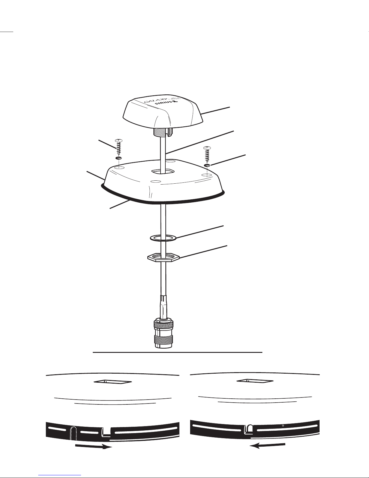
Supplied parts (all versions):
(1) SRA-25 Antenna with 6” cable and TNC Female connector
(1) 25’ Coax Cable with TNC Male and SMB connectors
(1) Bag containing: (1) Extension shaft, (1) Lockwasher, (1) Retaining nut
This instruction sheet
Some versions may also include the following supplied parts:
(1) Surface Mounting Base
(1) Mounting Gasket with slot for passing the coax cable
(4) Self-tapping stainless steel mounting screws
Tools required: Screwdriver. Marking pencil, drill and drill bits (9/16”,
7/64”), needle nose pliers, or other tools appropriate to your specic application
may also be needed.
Required materials: Silicone Sealer (RTV) when ush mounting
DO NOT CUT OR ALTER THE ANTENNA CABLE.
DO NOT REMOVE ITS CONNECTOR.
IMPORTANT: Please read all instructions before installing.
Optional Accessories
SRS-1 DC Voltage Splitter for antenna cables up to 50’
SRS-2 DC Voltage Splitter for antenna cables over 50’
SRS-3 Connects two Sirius receivers to one Galaxy Satellite Antenna
SRC-35 35’ RG-58 cable kit with connectors
SRC-50 50’ RG-58 cable kit with connectors
SRC-90 90’ RG-8X cable kit with connectors
SRC-135 135’RG-8Xcablekitwithconnectorsandinlineamplier
SM-32 Low-ProleSurfaceMountingKitforlocationswithoutaccess
under the antenna for attaching nuts and bolts.
The length of the cable run from the antenna to the satellite radio receiver can be
extended by using one of the optional cable kits listed above. Note: These cables
replace the 25’ cable supplied with the antenna, and must be used as supplied. They
cannot be lengthened, shortened, or connected together as extensions.
Galaxy®Style SRA-25
Electronic Products Group
6111 Shakespeare Rd., Columbia, SC 29223 · 803-227-1590 · Fax: 803-419-3099
www.shakespeare-marine.com
rev. 10-19-2006
Satellite Shooter Template
Trace the triangle below on a sheet of paper, then cut out the triangle
and use as a template on thick paper or poster-board.
1. Tape this edge to paper tube or straight edge.
2. Sight through tube or top of straight edge for
clear view of sky.
This corner should be next to the mounting hole
when scanning.
This edge must be kept horizontal at the mounting location
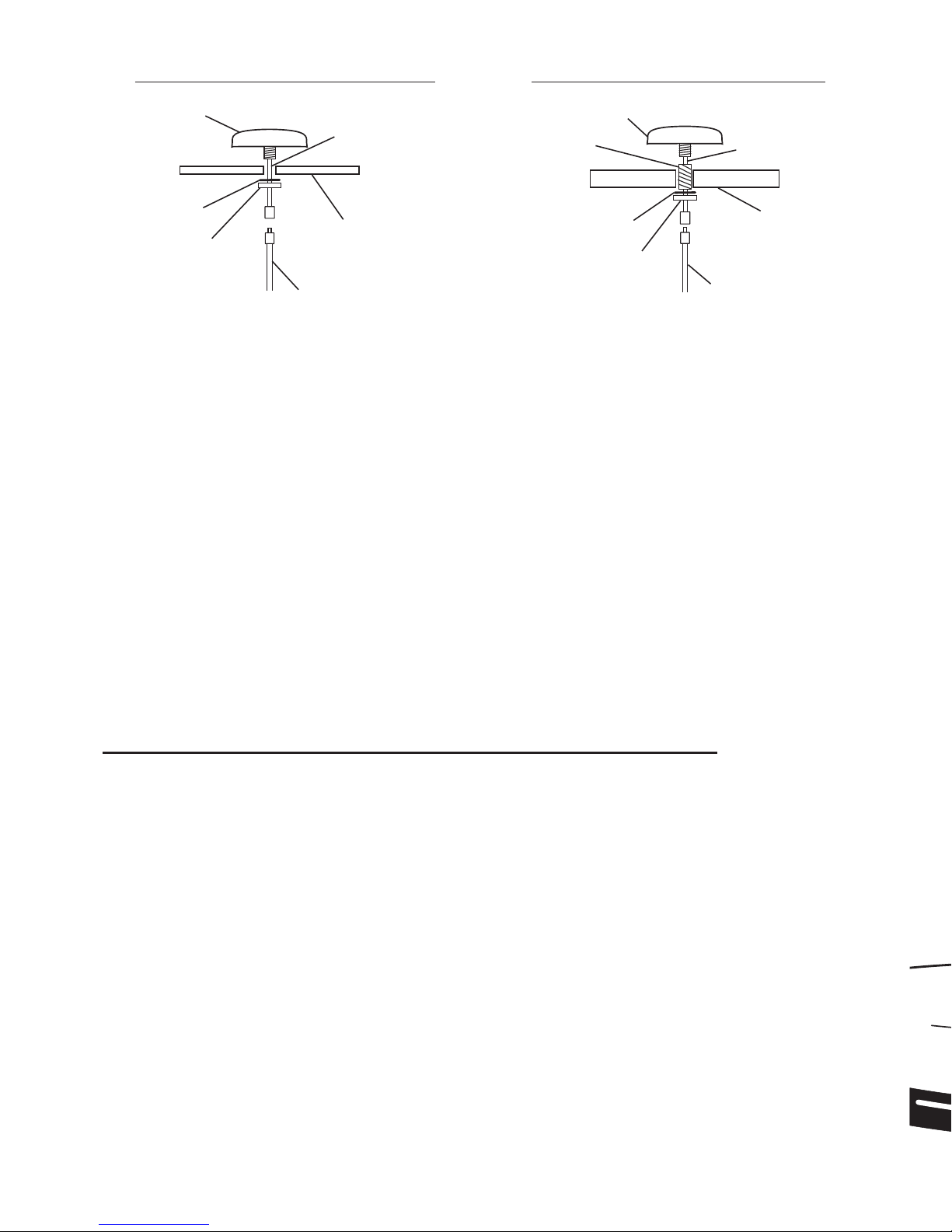
If you are running the cable through the side of the Mounting Base:
(Option b)
Step 1b: Attach the SRA-25 antenna to the Mounting Base using the washer
and nut as shown in the diagram at right). Use the assembly as a template to
mark locations for the mounting screws
Step 2b: Position the gasket so that the cable exit notch is available to make a
neat seal, as illustrated on page 4, and route the cable through the base.
Step 4b: Position the cable in the gasket’s slot while tting the gasket into
position in the Mounting Base.
Step 5b: Attach the assembly to the surface, orienting it so that the cable notch
faces away from oncoming wind. Do not overtighten.
The supplied mounting screws will accommodate most surfaces. If you nd
them too long, too short, or otherwise unsuitable for your application, substitute
wood screws, machine screws/washers/nuts, or other hardware (not supplied).
Be sure to use only stainless steel hardware, and be sure to use the four supplied
grommets with the hardware you choose. If you nd it too difcult to start the
screws, drill 7/64” pilot holes.
Skip to “Completing the installation” below.
Completing the installation
Step 1: Route the cable to your satellite radio receiver.
IMPORTANT: If your satellite receiver is an older model that has two
antenna input terminals, the optional SRS-1 Splitter may be required. Newer
models may differ, so consult your dealer or Shakespeare for up-to-date
information.
Step 2: Attach the SMB connector to your satellite radio receiver. See the
receiver’s manual for precautions and instructions. Done!
“Sirius” and related marks are trademarks of Sirius Satellite Radio, Inc.