Wood and Douglas RSX150G User manual

1892 1139 - RSX Range of Intelligent Modems User Guide - v7.1 / Nov 2007 1
RSX RANGE OF INTELLIGENT MODEMS
USER GUIDE
1892 1139
Figure 1 - RSX Series Radio Modem Figure 2 - OEM version
This manual is intended to provide you with sufficient information to install and operate an
RSX radio modem correctly.

21892 1139 - RSX Range of Intelligent Modems User Guide - v7.1 / Nov 2007
Contents
INTRODUCTION ....................................................... 3
Part One: Installation and Normal Operation ................................ 4
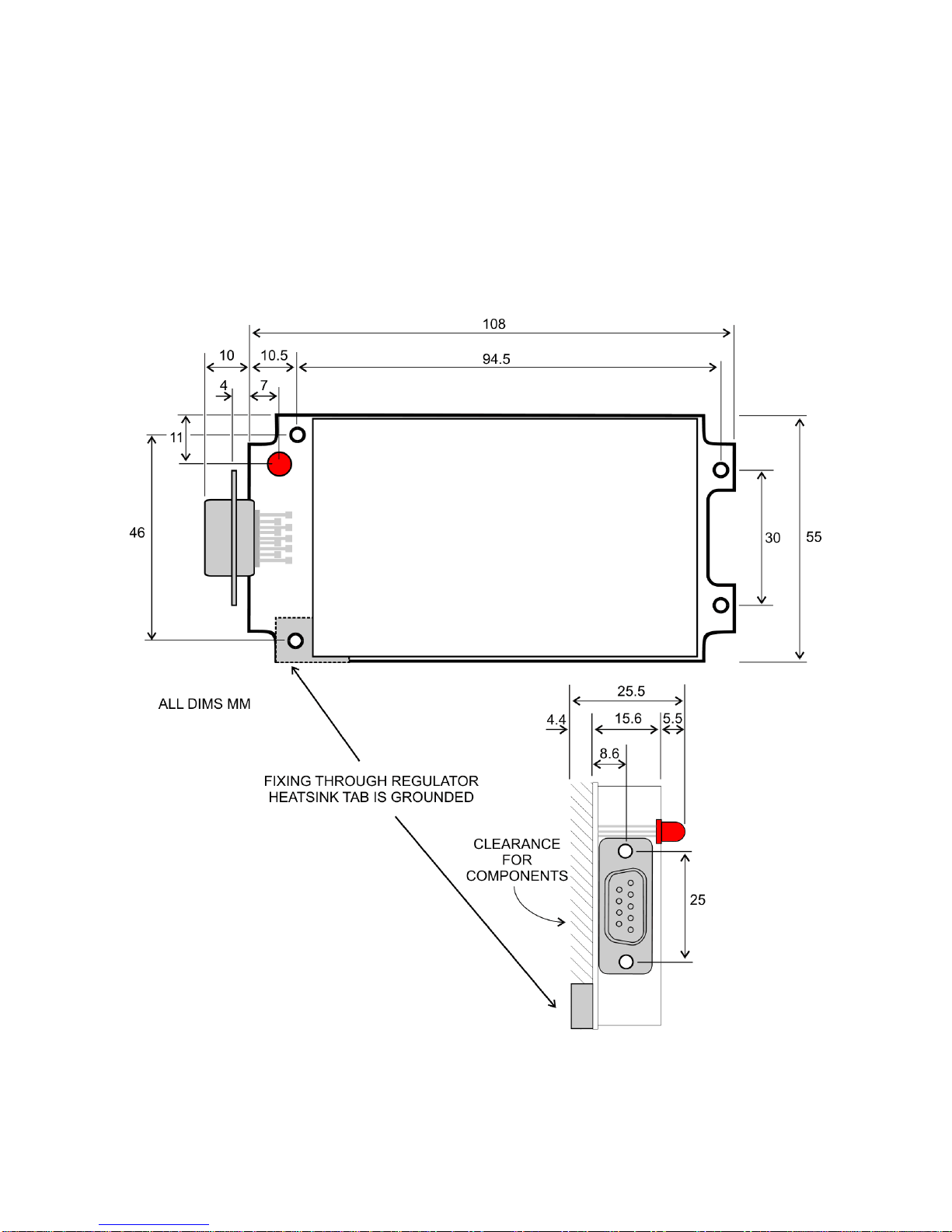
1.1 DIMENSIONS AND INSTALLATION .............................. 4
1.1.1 Standard Die-Cast Enclosure .............................. 4
1.1.2 OEM PCB ............................................. 5
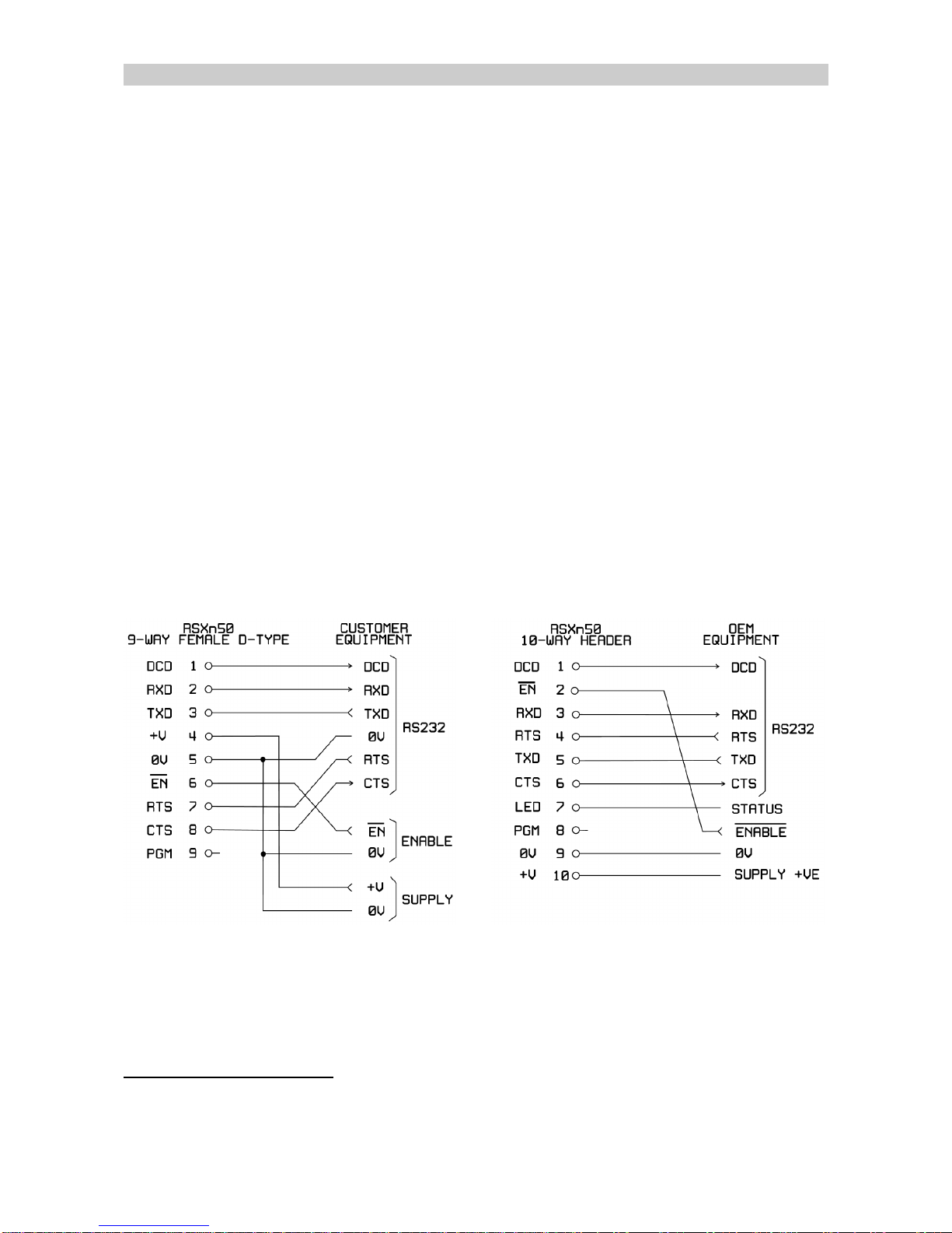
1.2 CONNECTIONS ............................................. 6
1.2.1 Connections to Customer Equipment ........................ 6
1.2.2 Connections to a PC .................................... 7
1.2.3 Detailed Information ..................................... 8
1.2.4 Power Supply and Current Consumption .................... 10
1.3 DURING OPERATION ....................................... 10
1.3.1 Control Signals ........................................ 10
1.3.2 LED Indications ....................................... 11
Part Two: Programming the Radio ....................................... 12
2.1 HARDWARE LINK SETTINGS ................................. 12
2.2 PROGRAMMING RADIO PARAMETERS - SXN50 ................. 13
2.2.1 Programming Adaptor for use with SNx50.exe software ........ 14
2.2.2 Obtaining and Running the Programming Software ............ 14
2.2.3 Changing unit settings .................................. 15
2.3 CHANGING CHANNEL USING SERIAL COMMANDS ............... 18
Part Three: Programming the Modem ..................................... 20
3.1 CHANGING MODEM PARAMETERS - WINSETGMSK .............. 20
3.1.1 Adaptor Cable ........................................ 20
3.1.2 Obtaining and Running the Programming Software ............ 20
3.1.3 Connecting ........................................... 21
3.1.4 Editing Parameters ..................................... 21
3.2 WINSETGMSK ADDITIONAL FEATURES ........................ 23
3.2.1 Terminal Mode ........................................ 23
3.2.2 Telemetry Test ........................................ 24
3.2.3 Closing WinSetGMSK .................................. 25
3.3 CHANGING MODEM PARAMETERS USING SERIAL COMMANDS .... 25
Part Four: Additional Information ........................................ 27
4.1 RANGE ................................................... 27
4.2 VARIANT MODELS .......................................... 28
4.3 TIMING ................................................... 29
4.4 TECHNICAL SPECIFICATIONS ................................ 30
APPENDIX: PCs WITHOUT RS232 SERIAL PORTS (COM PORTS) ............. 31
APPENDIX: SXn50 RADIO PROGRAMMING SOFTWARE REFERENCE .......... 32
APPENDIX: TERMINAL KEYSTROKES .................................... 36

1892 1139 - RSX Range of Intelligent Modems User Guide - v7.1 / Nov 2007 3
INTRODUCTION
The Wood & Douglas RSX Series Radio Modems are high-speed intelligent radio
modems providing a half-duplex data link over a distance of up to several kilometres,
depending on the frequency chosen. They use GMSK (Gaussian Minimum Shift Keying)
modulation to achieve an RF data rate of 4800 baud in a 12.5kHz channel and 9600 baud
in a 25kHz channel. Serial data is passed to and from the modem via an RS232 port at
speeds of up to 38,400 baud, and all buffering and radio management is carried out
transparently by the unit.
The unit will typically be used as supplied with no setup required, wired to customer data
equipment and a power supply. However, the modem and radio parameters are user-
configurable if required, either by sending serial codes or using proprietary set-up
software obtained from the Wood & Douglas website (www.woodanddouglas.co.uk) or
Sales at Wood & Douglas.
The modem uses the SXn50G range of radios which are high quality, very compact
synthesized transceivers producing 500mW maximum RF output. The SXn50G range is
approved to EN 300 220 and ETS 300 086. The UHF SX450G is also approved to
MPT1411. The RSXn50G is approved to ETS 300 113 making it universally attractive for
both telemetry and mobile radio data.
The three variants in the RSX series are:
RSX150G covering the range 100 - 225MHz
RSX450G covering the range 400 - 490MHz
RSX850G covering the range 868 - 870MHz
collectively referred to as RSXn50.
Units can be ordered covering a frequency band within these ranges, and operate by
default on a particular frequency within that band.
The RSXn50 is available in a rugged diecast enclosure for general use, or as an OEM
PCB for inclusion in other equipment.

41892 1139 - RSX Range of Intelligent Modems User Guide - v7.1 / Nov 2007
1Part One: Installation and Normal Operation
1.1 DIMENSIONS AND INSTALLATION
Unless supplied as an OEM PCB, the RSXn50G is supplied in a die-cast enclosure.
1.1.1 Standard Die-Cast Enclosure
Dimensions and mounting by means of four off M4 holes is shown in Figure 3.
Figure 3 Mounting details
Figure 4 - RSX in use
A whip antenna may be attached directly to the BNC
connector, and in this case the unit would typically
be mounted vertically. The antenna must be in a
suitable position - for example, against a metal
panel would not be suitable. See Figure 4.
Otherwise, the connection to the antenna should be
made with a short length of high-quality coaxial
cable. This is particularly important at higher
frequencies to avoid losses.
The data connector should be secured with screws
to the bushes provided for a reliable connection.

1892 1139 - RSX Range of Intelligent Modems User Guide - v7.1 / Nov 2007 5
1.1.2 OEM PCB
If supplied as an OEM PCB, the unit has dimensions and mounting as shown in Figure 5.
It can also be supplied with a PCB connector rather than the 9-way D-type connector
shown.
The unit requires a small amount of heatsinking for the on-board regulator to dissipate of
the order of 2W. This is provided in the cased version by the regulator being screwed
down to a supporting pillar in the diecast case. The heatsink tab is connected to system
0V, and so requires no insulators where the heatsink may be grounded.
Figure 5 - OEM PCB version mounting details

1Older models required 9V - 15V. Models are listed on page 28, and you can check the
model of your unit from the label on the bottom of it.
61892 1139 - RSX Range of Intelligent Modems User Guide - v7.1 / Nov 2007
1.2 CONNECTIONS
The antenna connects by means of a 50OBNC connector on the standard unit. A 200mm
coaxial flying lead is supplied with the OEM PCB.
All other connections to the unit are made via a male 9-way D-type connector (optionally a
10-way IDC connector on an OEM PCB), incorporating a serial interface, supply input and
a remote on/off control. This interface is used for three separate functions: radio
programming, modem programming and normal operation.
If you are using a computer which has no serial port, see the Appendix on page 31 for
USB to serial adaptors.
A power supply of 5 to 15V DC is required1. The current drawn depends on the supply
voltage and unit activity as shown on page 10.
The remote on/off (Enable) input must be held low (0V) when the unit is to operate. At
other times, it can be held high (+2V to supply positive) to reduce the supply current to a
very low level (‘sleep mode’), for example where power is supplied from a battery.
1.2.1 Connections to Customer Equipment
The diagrams in Figure 6 and Figure 7 show the connections for the standard version
and the IDC header option (OEM PCB versions only) respectively.
Figure 6 - 9-way D-type connector Figure 7 - 10-way IDC connector
vNote that if there is no remote on/off, EN must be linked to 0V in order for the radio
modem to function.

1892 1139 - RSX Range of Intelligent Modems User Guide - v7.1 / Nov 2007 7
1.2.2 Connections to a PC
The standard version of the RSXn50 may be connected to the serial port of an IBM-
compatible personal computer using the connections shown in Figure 8.
Figure 8 - Connections to a PC serial port
vThese connections are also used when programming the modem (not the radio).
If you are using a computer which has no serial port, see the Appendix on page 31 for
USB to serial adaptors.

81892 1139 - RSX Range of Intelligent Modems User Guide - v7.1 / Nov 2007
1.2.3 Detailed Information
9-way D-type socket
10-way IDC header
Pin Pin Name Function In/out Remarks
1* 1* DCD Data Carrier
Detect/Readback RS232
output +10V = signal received, squelch open
-10V = no signal received, squelch closed.
In radio configuration mode, Readback.
23RXD Data output from
modem RS232
output Serial data from modem to external device
35TXD Data input to
modem RS232
input Serial data from external device to modem
410 +V Supply Input 5 to 15V DC supply (but see p.28 for
earlier models)
59GND 0V Ground System Ground
62EN Enable Input Remote ON/OFF
0V = ON, +V (supply) or floating = OFF
74RTS Ready To Send
input RS232
input From external device to RSX. See below.
86CTS Clear To Send
output RS232
output From RSX to external device. See below.
98PGM Program radio RS232
input Note: this input should be left open circuit
during normal use.
n/a 7LED LED Status Output Logic low (0V) indicates No Lock error
(equivalent to orange LED indication)
Table 1 - Connection details
1.2.3.1 RTS
This table summarises what the RSXn50 expects to see on the RTS input under various
circumstances:
Modem
function
Normal Operation Programming
modem with
WinSetGMSK
Programming
radio
Transmitting data Idle
RTS
state High Don’t care True connection to PC Ignored
May be wired high or true connection
1.2.3.2 CTS
During normal operation, the RSXn50 takes the CTS output low to inhibit data input from
customer equipment. This is necessary under two circumstances:

1892 1139 - RSX Range of Intelligent Modems User Guide - v7.1 / Nov 2007 9
1. When the modem buffer is full
2. When there is a signal on-channel (indicated by the squelch being active high) and
transmission cannot therefore take place. When the TX squelch override is
enabled, transmission is permitted, and CTS remains high.
If the input data rate is less than the over-air data rate and there is therefore no danger of
buffer overrun, and transmission will never be inhibited by the squelch because the TX
squelch override is enabled, the CTS output can be left disconnected and the
corresponding input at the customer equipment can be wired high.
vA true connection to the PC is essential when programming the modem using the
WinSetGMSK software.
This table summarises the RSXn50 CTS output state under various circumstances:
Normal Operation Programming
modem with
WinSetGMSK
Programming
radio
TX Buffer state Full Not full N/A N/A
Squelch state Don’t care Inactive Active N/A N/A
TX Squelch
Override Don’t care Don’t care Disabled Enabled N/A N/A
CTS output Low High Low High Used by software N/A
1.2.3.3 PGM
This input is used solely for radio programming, and has no function during normal use. It
should be left open-circuit, as any spurious signals applied could cause the SXn50
transceiver to become incorrectly programmed, indicated by the orange LED lighting or a
logic low on the LED output (OEM version with IDC connector only).
1.2.3.4 RS232 Levels
The RSXn50 provides a bipolar output of +10V on RS232 lines which should be
acceptable to the vast majority of RS232 interfaces. These levels have the conventional
significance, as follows:
Voltage Name Logic level Assertion (RTS etc) Bit value (data)
+10V Space High True 0
-10V Mark Low False 1
It will also accept non-RS232 level inputs as supplied by some PCs, where
high is between +2V and +supply
and low is between -supply and 0V.

2Older models required 9V - 15V. Models are listed on page 28, and you can check the
model of your unit from the label on the bottom of it.
10 1892 1139 - RSX Range of Intelligent Modems User Guide - v7.1 / Nov 2007
Note: The information in this section applies to normal operation, and not to the PGM (pin
9) and Readback (pin 1) interface during radio programming.
1.2.4 Power Supply and Current Consumption
The RSXn50 requires a power supply of 5 to 15V DC (12V DC nominal)2. Because the
circuitry includes switched-mode power supplies, the current consumed varies inversely
with input voltage, and the external power supply must be capable of supplying the
corresponding current shown in the table below.
Input
State 5V 9V 12V 15V
Standby 100mA 70mA 60mA 50mA
RX 120mA 80mA 70mA 60mA
TX 5mW 120mA 80mA 70mA 60mA
TX 500mW 400mA 250mA 200mA 160mA
Table 2 - Supply current for various input voltages and activities
Note: Connection to a vehicle supply without proper external transient suppression can
cause the internal configuration data to be corrupted. Under these circumstances
the modem will revert to the default modem settings.
1.3 DURING OPERATION
1.3.1 Control Signals
The RSXn50 modem uses hardware flow control. Whenever customer equipment wishes
to send data, it should ensure that RTS is high. Provided it is answered with CTS high
from the RSXn50, it may start to send serial data at any of the permissible rates (see
specification). Do not send data with RTS low, as this could be interpreted as a command
code.
The RSXn50 brings CTS low if its transmit buffer becomes full and it cannot accept further
data to transmit at present. CTS is also brought low if transmission is not possible
because the squelch has operated, indicating received signals on the channel (provided
the option to override it has not been enabled). Any data sent during this condition will be
lost.
The DCD line is brought high to indicate that a signal is being received (squelch is open).
Received data is output to the customer equipment.

1892 1139 - RSX Range of Intelligent Modems User Guide - v7.1 / Nov 2007 11
The unit normally suppresses transmission when the squelch is open, but may be
configured to ignore it if required. (See page 22.)
1.3.2 LED Indications
LED
Figure 9 - RSX Series Radio Modem
A three-colour LED visible through the top of the enclosure confirms the functional state of
the modem:
RED -The modem is in transmit mode
GREEN -The modem is in receive mode
ORANGE -The radio has failed (i.e. is out of lock).
Out of lock may occur if the radio has been programmed incorrectly such that the
synthesiser will not lock. One cause of this is setting a frequency out of the radio’s
bandwidth, which is set at manufacture.
The Out-of-lock state is duplicated as a logic low on the LED output available on the OEM
IDC connector version only.

12 1892 1139 - RSX Range of Intelligent Modems User Guide - v7.1 / Nov 2007
2Part Two: Programming the Radio
2.1 HARDWARE LINK SETTINGS
Some options may be configured to user requirements using the on-board links as
detailed in the following table. With the exception of LK7, they all relate to radio
operation.
Link Function Settings
LK3 +Vin/LED closed when 9-way D-type connector is fitted
open when 10 way IDC is fitted*
LK4
Over-air baud rate
closed
= 4800
open
= 9600LK5 closed open
LK6 open closed
LK7 EEPROM write enable (applies
to modem settings only) closed = enable (default setting)
open = write protect
LK9 +Vin/LED open when 9-way D-type connector is fitted
closed when 10 way IDC is fitted*
LK10 LED enable closed = enable (default setting)
open = disable
LK11 Transmitter power 1 - 2 = 500mW (default setting)
2 - 3 = 5mW
Table 3 - Link Settings *OEM version only
These links are only accessible with the PCB removed from the enclosure, and are all on
the underside of the board (the radio module being on the upper side).
To remove the PCB from the enclosure:
1. Undo the four screws on the top of the unit and remove the lid.
2. Undo the two hexagonal bushes which secure the D-type connector, being careful
to retain the mounting plate and any nuts and washers from the inside of the
enclosure.
3. Undo the four screws which hold the PCB in place in the enclosure.
4. Lift the PCB out of the case, and pull the miniature coaxial connector out of the
radio module socket so that the PCB is completely free of the enclosure.
vIt is not necessary to remove the BNC antenna socket.
To reassemble the unit, reverse the instructions.

1892 1139 - RSX Range of Intelligent Modems User Guide - v7.1 / Nov 2007 13
The links can be found as shown in Figure 10.
Figure 10 - Link Positions on RSXn50 PCB underside
Links are made and broken by adding and removing a solder bridge between pads on the
board as shown below.
Figure 11 - Link adjustments
2.2 PROGRAMMING RADIO PARAMETERS - SXN50
The RSXn50 is normally supplied with a table of channel frequencies preset, and the
radio set to use channel 0. However, you can select another channel as the current
operating channel and/or reprogram the table to other frequencies (within the ‘switching
bandwidth’ which is a fixed attribute of the radio hardware). Certain other parameters are
also programmable, as detailed below.
Radio parameters are programmed by connecting a unit to a standard PC serial port using
a special adaptor cable and using a program, SXn50.exe, which you can download from
the Wood & Douglas website (www.woodanddouglas.co.uk).
vIf you are using a computer which has no serial port, see the Appendix on page 31
for USB to serial adaptors.

3Older models required 9V - 15V. Models are listed on page 28, and you can check the
model of your unit from the label on the bottom of it.
14 1892 1139 - RSX Range of Intelligent Modems User Guide - v7.1 / Nov 2007
Alternatively, you can send single serial bytes (for example, from a terminal) to select a
new channel. See page 18.
Modem parameters are set separately: see page 20.
2.2.1 Programming Adaptor for use with SNx50.exe software
The RSXn50 requires a special adaptor cable between itself and the PC serial port, which
also connects the 5 to 15V DC supply3. This cable is shown in Figure 12.
Figure 12 - Radio programming adaptor
vThe RSXn50 provides true RS232 readback from pin 1, and so should be
compatible with any PC.
2.2.2 Obtaining and Running the Programming Software
vIf you have already obtained and installed the software, go to step 3
vThe Appendix on page 32 contains a reference covering the functions of the
SXn50.exe software.
.
1. Download the latest version of the programming software SXn50.exe from the
Wood & Douglas site on the internet. The URL (address) is:
www.woodanddouglas.co.uk
(In case of difficulty, contact Sales at Wood & Douglas, contact details on the last

1892 1139 - RSX Range of Intelligent Modems User Guide - v7.1 / Nov 2007 15
page of this manual.)
2. Open the Zip file and run setup.exe, which will install the software for you.
3. Run the SXn50.EXE program. It will run in a normal window with both mouse and
keyboard support.
At this stage, the main window is displayed as shown in Figure 13.
Figure 13 - Programming screen
The screen shows the default settings which are displayed whenever the software is run.
The menu bar at the top lists a number of headings, under which there are usually
additional menu items, representing actions. Below this, there is the Frequency Table.
The leftmost column lists the channel numbers. Ignore the Parallel column. The next
column, TX Frequency, is used to set and display channel frequencies.
Use the Port Setup > Com Port > COM1 etc. menu selection to select the port to which
your adaptor is connected.
2.2.3 Changing unit settings
Three steps are necessary:
vUpload information from the unit
vEdit the information
vDownload information to the unit

16 1892 1139 - RSX Range of Intelligent Modems User Guide - v7.1 / Nov 2007
2.2.3.1 Reading Current Unit Settings
First, you must read into the computer what is in the unit’s memory at present. To do this,
press F5 or select Link > Read from the Unit > Upload All from SXn50G. The data
replaces the defaults on the screen and fills in the unit details.
vThe program insists that you do this before allowing you to reprogram the unit to
make it less likely that inappropriate values be entered.
vHowever, once you have uploaded during a session, you may edit and download
the data to as many units as you wish.
If you just want to change the operational channel, skip to section Setting Operational
Channel on page 17.
2.2.3.2 Selecting Table Type
The SXn50G can hold either a table of 80 individually-chosen Tx frequencies and Rx
offsets, or a table of 256 equally-spaced Tx frequencies all with the same Rx offset.
To select the table type, select Parameters > Number of Channels > 80 or 256.
2.2.3.3 Programming 256 Channels as a Block
It is necessary to specify the starting frequency (the lowest, corresponding to channel 0),
a spacing or step value, and an Rx offset. The spacing is expressed in multiples of the
Comparison Frequency (including 0, which makes all frequencies the same).
Double-click the Tx Frequency value for channel 0 in the main frequency table, which
brings up this dialog:
Figure 14 - Frequency Programming Dialog
vThe list displays all valid values for the starting frequency, that is, frequencies
within the switching bandwidth which are multiples of the Comparison Frequency.
Select a Table Start frequency from the list and a Table Step and click OK. The dialog is
removed and the main table shows the channel frequencies.

1892 1139 - RSX Range of Intelligent Modems User Guide - v7.1 / Nov 2007 17
To set the Rx Offset for the whole table, select Parameters > Rx Offset and pick from the
list of possible values.
2.2.3.4 Programming Up To 80 Channels Individually
Double-click the Tx Frequency value for the channel to program in the main frequency
table, which brings up this dialog:
Figure 15 - Frequency Programming Dialog
vValid values for the starting frequency are frequencies within the switching
bandwidth which are multiples of the Comparison Frequency.
Select a Table Start frequency, ignoring the other parameters, and click OK. The dialog is
removed and the main table shows the channel with its new frequency.
To set the Rx Offset for the channel, select Parameters > Rx Offset and pick from the list
of possible values.
It is also possible to program a range of channels automatically in a similar way to the 256
channel block. In the Frequency Programming Dialog, select the range of channels
required (the From and To drop-downs), a Table Start and Channel Step, and click OK.
The dialog is removed and the main table shows the channels with their new frequencies.
It is not possible to select Rx Offset for a range of channels; this must be done
individually.
2.2.3.5 Setting Operational Channel
The unit must be told which of the 80 or 256 channel settings to use when it is powered
up. To set the operational channel, double-click on the channel number in the frequency
table. The row is highlighted to indicate that this is the operational channel.
2.2.3.6 Downloading New Settings to Unit
As yet, the settings have only been edited in the program. To download them to the unit,
press F6 or select Link > Write to the Unit > Download All to SXn50G

18 1892 1139 - RSX Range of Intelligent Modems User Guide - v7.1 / Nov 2007
vThis is only permitted if the Read from Unit command was previously used to
upload settings at some point during the session.
vIf you did not do this, save the configuration to disk, read the unit, and then retrieve
the configuration again. See below.
2.2.3.7 Completing Programming
This completes programming and the unit may be disconnected. It is not necessary to
switch off power or stop the program first.
2.2.3.8 Programming Further Units
Further units may be programmed by disconnecting one unit and connecting the next,
which may be done without switching the power off.
Proceed as above, downloading the configuration when all the channel parameters are
correct. For identically-programmed units, downloading is all that is necessary.
2.2.3.9 Saving and Retrieving Configurations
It is possible to save and retrieve configurations on disk for later use.
To save a new configuration, select File > Save Parameters As. To save a previously
saved configuration, select File > Save Parameters.
To retrieve a configuration, overwriting any existing configuration on the screen, select
File > Load Parameters.
vThis feature is also useful if you find that you cannot program a unit because you
omitted to read it first. Save your edited configuration, read the unit, then retrieve
the configuration.
2.3 CHANGING CHANNEL USING SERIAL COMMANDS
The channel can be changed by sending a serial channel number 0-255 as a single
RS232 byte on pin 9 (PGM). The protocol is:
9600 baud, RS232 levels, 1 start bit - 8 bit data - no parity - 1 stop bit
Single-byte, channel number in binary, LSB first (decimal 0 to 255)
Idle state for at least 40ms before and after byte.
As soon as the message is recognised as a valid command, the channel is changed. No
confirmation is required, and the setting is remembered during unit power off.

1892 1139 - RSX Range of Intelligent Modems User Guide - v7.1 / Nov 2007 19
This can be achieved by any equipment with an RS232 serial port which can send the
required byte. Only the TXD (to pin 9) and ground (to pin 5) connections are required.
Figure 16 - Serial channel change connections (terminal pinout shown)
vIf you use a terminal, the equivalent keystrokes for channels 0 to 127 are listed in
the appendix on page 36.

20 1892 1139 - RSX Range of Intelligent Modems User Guide - v7.1 / Nov 2007
3Part Three: Programming the Modem
3.1 CHANGING MODEM PARAMETERS - WINSETGMSK
vModem parameters may be protected from change by a hardware link setting
described on page 12.
If you want to change modem parameters, they can be programmed by connecting a unit
to a standard PC serial port and using a program, WinSetGMSK.exe, which you can
download from the Wood & Douglas website, www.woodanddouglas.co.uk.
It is also possible to program the modem using command sequences of serial bytes. See
page 25.
Radio parameters are set separately: see page 13.
3.1.1 Adaptor Cable
The unit should be connected to the computer serial port using the type of cable shown in
Figure 8 on page 7. The RTS and CTS connections are essential in this case.
3.1.2 Obtaining and Running the Programming Software
vIf you have already obtained and installed the software, go to step 3
1. Download the latest version of the programming software WinSetGMSK.exe from
the Wood & Douglas site on the internet. The URL (address) is:
www.woodanddouglas.co.uk
(In case of difficulty, contact Sales at Wood & Douglas, contact details on the last
page of this manual.)
2. Open the Zip file and run setup.exe, which will install the software for you.
3. Run the WinSetGMSK program. It will run in a normal window with both mouse
and keyboard support.
At this stage, the main window is displayed but behind a dialog shown in Figure 17.
This manual suits for next models
2
Table of contents