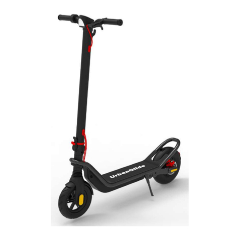
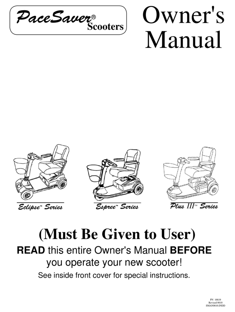
Skoot-Eze TBSC79020 User manual

CAUTION
Read all warnings and instructions
in this manual before using the
scooter. Keep this manual for future
reference.
User’s Manual
Model No. TBSC79020
Model No. TBSC79920
Table of Contents
Important Precautions . . . . . . . . . .2
Before You Begin . . . . . . . . . . . . .3
How to Set Up the Scooter . . . . . . .4
How to Operate the Scooter . . . . . .6
Maintenance and
Troubleshooting . . . . . . . . . . . . . . .8
Part List . . . . . . . . . . . . . . . . . . . .11
How to Order
Replacement Parts . . . . . . . . . . . .11
Limited Warranty . . . . . .Back Cover

2
Important Precautions
WARNING:To reduce the risk of serious injury, read these warnings before using the scooter.
1. Read, understand, and follow all warnings and
instructions on the scooter and in this manual.
Save this manual for future reference.
2. It is the owner’s responsibility to ensure that all
users of the scooter are adequately informed of,
and follow, all warnings and instructions.
3. Inspect the scooter and tighten or replace any
loose or missing parts before each use. In addi-
tion, make sure that the wheels rotate freely; the
wheel bolts are tight; the horn, turn signals, mir-
ror, and front light function well; and the brake
is properly adjusted and working.
4. Keep the tires properly inflated. Do not use the
scooter if the tires are underinflated; this can
cause loss of control and can damage the motor
or batteries.
5. Always wear protective equipment, including a
helmet, knee pads, wrist guards, elbow pads, and
closed-toed shoes, when using the scooter.
6. Keep children away from the scooter at all times.
Always turn the key to the off position and
remove it when the scooter is not in use. Always
store the scooter in a protected area where unau-
thorized use is prevented.
7. The scooter should not be used by children.
8. Never ride the scooter on streets, roadways, or
driveways that enter vehicle traffic routes. Always
comply with all local laws and regulations. Use
the turn signals before turning.
9. The scooter is not recommended for riders
weighing more than 300 pounds. To prevent seri-
ous injury or damage to the scooter, do not
exceed this maximum user weight limit.
10. Never ride the scooter on wet or uneven surfaces
or when visibility is poor. Use the front light in
darkened conditions.
11. Do not allow more than one person to ride the
scooter at a time. Never tow another person or
vehicle behind the scooter. Never allow the scoot-
er to be towed behind a bicycle, motorcycle, or
vehicle.
12. Never place hands near moving parts when the
power is on. Make sure the on/off switch is in the
off position before performing any of the mainte-
nance or troubleshooting procedures described
in this manual.
13. Do not ride the scooter on unpaved surfaces. Do
not leave the scooter in dusty, wet, or rainy
areas. Clean the scooter after each use with a
damp cloth and a small amount of mild deter-
gent. Keep the batteries and electronics dry and
protected from dirt and contaminants. Charge
the scooter only in a dry, well-ventilated area
and follow all instructions.
14. Ride the scooter only in the restricted speed set-
ting until you have familiarized yourself with the
operation of the scooter. Always use the restrict-
ed speed setting when riding the scooter indoors
or when riding the scooter in reverse.
15. The scooter is capable of high speeds, even when
the motor is first started. Adjust the speed in
small increments to avoid sudden jumps in
speed.
16. Use only the supplied charger to charge the
scooter. Do not use the charger or the scooter if
any wires or electric components become dam-
aged or frayed. Use only components or parts
supplied by the manufacturer for all repairs and
replacements.
17. Never remove the nuts holding the rims together
without first deflating the tires.

3
Before You Begin
Thank you for selecting the new SCOOT-EZE™motorized scooter. The SCOOT-EZE motorized scooter combines
quiet electric power with a sturdy, compact design to provide you with comfortable motorized transportation. For
your safety and benefit, carefully read all of the warnings and instructions in this manual before using the
scooter.
Before reading further, please take a moment to familiarize yourself with the parts of the scooter that are labeled in
the drawing below.
A caution decal has been placed on the scooter in the location shown above. If the decal is missing or illegible,
please call our Customer Service Department toll-free at 1-800-999-3756, Monday through Friday, 6 a.m. until
6 p.m. Mountain Time, to order a free replacement decal. Apply the replacement decal in the location shown.
Headlight
Seat Clamp
Seat
Horn
On/Off Keys
Handlebar
Handgrip Throttle
Battery Cover
Basket
Cover Keys
Bumper
Caution Decal Upright Latch
Brake Handle
Power Display
Upright
Mirror

4
How to Set Up the Scooter
Follow the steps below to set up the scooter for use. Assembly requires the included tool kit.
2. Insert the Right Handlebar (26) into the crossbar on the
Upright (41) as shown. Attach the Right Handlebar by
tightening a Handlebar Screw and Handlebar Washer
(22) into the outer hole in the crossbar.
Attach the Left Handlebar (27) to the crossbar in the
same manner.
See the inset photograph. Remove the screw (not
shown) from the indicated hole. Tighten the Mirror (24)
into the hole until the Brake Handle (28) is held securely.
3. Insert the Bumper (8) into the indicated tubes on the
frame. Note: It may be necessary to use a rubber mallet
to fully insert the Bumper.
Tighten a Bumper Screw (not shown) into the indicated
hole in each of the tubes on the frame.
4. Open the lever on the Seat Clamp (3). Insert the Seat
Post (2) into the frame. Close the lever on the Seat
Clamp.
2
1. See the inset photograph. Press and hold down the
Upright Latch (19). While holding down the Upright
Latch, fully raise the Upright (41).
Raise the Upright Latch (19), making sure that the latch
pins snap securely into the holes in the bracket on the
Upright (41). Securely fasten the Upright Latch by fold-
ing down the lever on the Upright Latch to the position
shown.
3
1
Latch Pin
19
41
41
19
Lever
Hole
Tube
8
Hole
24
28
26
22
41
27
4
2
Frame
3

6. The Basket (4) can be attached to either the rear of the
scooter or the front of the scooter. To attach the Basket
to the rear of the scooter, follow the instructions in this
step. To attach the Basket to the front of the scooter,
refer to step 7.
Place the Basket (4) in the position shown. Hold the
Saddle Bracket (7) around the Seat Post (2) as shown in
the inset photograph, and hold a Flat Bracket (43) on the
opposite side of the Basket. Attach the Flat Bracket and
the Basket to the Saddle Bracket with the two Saddle
Bracket Bolts (5) and the two Saddle Bracket Nuts (6).
5. Make sure that the on/off key is removed from the
on/off switch (see USING THE ON/OFF KEY on page
6). Unlock and open the battery cover (not shown).
Locate the plastic fuse holder. See the inset photograph.
Press the long tab in the center of the fuse holder, and
open the fuse holder. Remove the fuse from the small
plastic clips inside of the fuse holder. Slide the ends of
the red wires onto the ends of the fuse, and then press
the ends of the red wires into the large plastic clips
inside of the fuse holder. Close the fuse holder. Note: An
extra fuse can be stored in the fuse holder.
Close and lock the battery cover.
7. Locate the two black posts on the front of the Upright
(41). Hold a Flat Bracket (43) against the two posts.
Hold the Basket (4) in the position shown, and hold
another Flat Bracket (43) on the opposite side of the
Basket. Attach the Flat Brackets and the Basket to the
two posts with the two Flat Bracket Screws (44).
IMPORTANT: Before using the scooter, make sure that the scooter is set up as described and that all parts are
securely tightened.
The batteries must be charged before the scooter can be used. Refer to CHARGING THE BATTERIES on page
6 for instructions.
7
6
5
7
2
44
4
43
41
44
4
Fuse
Holder
543
6
Fuse
Red Wires
5

6
How to Operate the Scooter
Important: Read all instructions in this section before
using the scooter.
CHARGING THE BATTERIES
The scooter’s sealed lead-acid batteries should be
charged and stored at temperatures between 50°F and
100°F (10°C and 38°C). If the temperature is warmer,
the batteries will discharge more rapidly. If the tempera-
ture is cooler, the scooter should be moved to a warmer
area while the batteries are being charged. Follow the
steps below to charge the batteries.
1. Make sure the on/off key has been removed before
recharging the battery. Important: If the motor is
operated while the batteries are being charged, the
battery charger will be damaged and the scooter
may also be damaged.
2. Locate the charging socket. Identify the cord on the
battery charger that fits into the charging socket and
plug the cord into the charging socket. Plug the other
cord on the battery charger into a 110-volt outlet. A
red light on the battery charger will illuminate.
3. Allow the batteries to charge until the red light on the
battery charger changes to green; the green light indi-
cates that the battery is full. After the batteries are
charged, unplug the battery charger from the 110-volt
outlet first and then unplug the battery charger from
the charging socket on the scooter.
For maximum battery life, avoid leaving the on/off key
in the ON position when the scooter is not in use. Avoid
draining the batteries. It is recommended that the batter-
ies be charged after each use. The batteries should be
charged at least once each month, even if the scooter is
not used.
If the batteries need to be replaced, refer to HOW TO
ORDER REPLACEMENT PARTS on page 11. Recycle
batteries according to federal and state laws.
STORING THE BATTERY CHARGER
The battery
charger can be
stored on top
of the batteries
inside the bat-
tery compart-
ment. To store
the battery
charger, unlock
and open the
battery cover, and place the charger on top of the batteries.
Close and lock the battery cover.
USING THE ON/OFF KEY
The on/off
switch on the
upright is the
main power
switch.
Inserting the
on/off key and
turning it to
either the
“ON” or the
“R” position will turn on the power and light the power
display. Each light in the power display represents 20%
of the batteries’ full charge. If all five lights are lit, the
batteries are fully charged; if 4 lights are lit, the batteries
currently hold 80% of their full charge, and so forth.
Turning the key to the “OFF” position will turn off the
power. Always turn the key to the “OFF” position and
remove it when the scooter is not in use.
Power
Display On/Off
Switch
Charging
Socket
Charging
Socket
Battery Cover
Battery Charger

OPERATING THE SCOOTER
To use the scooter, first hold the handlebars securely,
step onto the deck, and sit down onto the seat. Next, turn
the on/off key to the restricted speed (“R”) position or to
the “ON” position. Note: If the restricted speed setting is
selected, the scooter will be restricted from reaching full
speed. Always use the restricted speed setting when
riding the scooter indoors or when riding the scooter
in reverse.
The scooter
can then be
started with
the handgrip
throttle on the
right handle-
bar. To start
the scooter,
securely grip
the handgrip
throttle and slowly roll it backward (counterclockwise).
The scooter will immediately begin to move. Move
your hand to roll the throttle slowly forward or backward
until the scooter moves at the desired speed.
Pull the brake
handle on the
left handlebar
to slow the
scooter quick-
ly. When the
handgrip
throttle is
released or the
brakes are
used, the
motor will stop. Important: Avoid frequently starting
and stopping the motor; frequent starting reduces the
batteries’ charge and may diminish battery life. Do
not repeatedly roll and release the handgrip throttle
in an attempt to move the scooter at a slower speed;
doing this may damage the motor.
Using the direction switch on the right handlebar (see the
photograph at the left), the scooter can be made to drive
backward as well as forward. Press the top of the switch,
marked “R,” to drive the scooter in reverse. When the
switch is set to reverse, a red light in the switch will be
lit. Adjust the speed with the throttle and brake as
described above. To drive the scooter forward, press the
bottom of the switch, marked “F.”
The left handlebar has several controls and a rear-view
mirror for your convenience and safety while riding the
scooter. (See the photograph at the lower left.) Use the
turn signal switch and horn button to signal your inten-
tions to others. The front light switch allows you to turn
on the front light in darkened conditions or when visibili-
ty is poor. Adjust the mirror to allow for a clear view of
what lies behind you.
Use the scooter only on paved, smooth, level surfaces.
Avoid using the scooter on grades steeper than 5% for
extended periods. Important: Avoid starting the motor
on an upward slope; starting the motor uphill strains
the motor and may diminish battery life.
The scooter is rated for use on a hard, level surface with
a surrounding temperature of 50°F and a maximum user
weight of 300 pounds; the batteries’ charge will be used
faster by heavier riders. With the batteries fully charged,
the scooter can travel up to 12 miles under optimal con-
ditions. Important: Make sure the tires are inflated to
the pressure listed on the sides of the tires; underin-
flated tires will strain the motor and batteries.
SELECTING A TONE FOR THE HORN
The horn on
the handlebars
can produce
eight different
tones. Turn the
indicated
selector knob
to select the
desired tone.
ADJUSTING THE HANDLEBARS
The handlebars can be adjusted for a closer grip. Refer to
assembly step 2 on page 4 and attach the handlebars at
the inner holes, rather than at the outer holes.
Throttle
CAUTION:Use the scooter only in
the restricted speed setting until you have famil-
iarized yourself with the scooter’s operation; the
scooter is capable of high speeds even when the
motor is first started. Adjust the speed in small
increments to avoid sudden jumps in speed.
Direction Switch
Turn Signal
Front Light
Horn
Brake Handle Horn
Selector
Knob
7

8
Maintenance and Troubleshooting
Regularly check the scooter and make sure that all parts
are properly tightened. If the scooter does not function
properly, follow the steps below. IMPORTANT: Always
turn the on/off key to the “OFF” position and remove
it before performing any of the steps below.
Symptom 1—The motor does not start when the
handgrip throttle is turned.
1. Make sure that the on/off key is in the on/off switch
and that the key is turned to either the “ON” or the
“R” position.
2. Make sure that the batteries are charged.
3. Make sure that the brake handle is not being pulled.
Symptom 2—The batteries discharge quickly.
1. Make sure that the tires are inflated to the pressure
listed on the sides of the tires.
2. Use the scooter on level, smooth surfaces. Avoid
using the scooter on grades steeper than 5%.
3. Charge and store the batteries at temperatures
between 50°F and 100°F (10°C and 38°C).
4. If the batteries still discharge quickly, new batteries
may be needed. Refer to HOW TO ORDER
REPLACEMENT PARTS on page 11.
Symptom 3—The brake is too loose or too tight.
1. Locate the
locknut and
adjustment
barrel on
the brake
handle.
Turn the
locknut
counter-
clockwise
to loosen it. Next, turn the adjustment barrel counter-
clockwise to tighten the brake or clockwise to loosen
it. Then, turn the locknut clockwise and retighten it.
Repeat until the brake is properly adjusted.
If the brake requires further adjustment, locate the
locknut and adjustment barrel near the lower end of
the brake
cable. Using
a small
open-end
wrench,
loosen the
locknut.
Next, turn
the adjust-
ment barrel
counterclockwise to tighten the brake or clockwise to
loosen it. Then, retighten the locknut. Repeat until the
brake is properly adjusted.
Symptom 4—The seat clamp is too loose or too tight.
1. If the seat
clamp does
not hold the
seat post
tightly, open
the lever.
Turn the
adjustment
nut clock-
wise one
half turn while keeping the lever from turning. Close
the lever. Repeat until the seat post is held tightly.
If the seat clamp cannot be closed, open the lever and
turn the adjustment nut counterclockwise one quarter
turn while keeping the lever from turning. Close the
lever. Repeat until the seat clamp closes and holds
the seat post tightly.
Symptom 5—The volume of the horn becomes weak.
1. The batter-
ies should
be replaced,
using two
“AA” bat-
teries (alka-
line batteries
are recom-
mended).
Remove the
two screws and remove the cover of the horn.
Replace the batteries. Make sure to match the + and
– symbols on the batteries with the symbols in the
battery compartment of the horn. Reattach the cover.
Locknut
Adjustment
Barrel
Locknut
Cable
Adjustment
Barrel
Lever
Seat
Clamp
Adjustment
Nut
Screws

Notes
9

10
Notes

How to Order Replacement Parts
To order replacement parts, call toll-free 1-800-999-3756, Monday through Friday, 6 a.m. until 6 p.m. Mountain Time
(excluding holidays). When ordering parts, please mention the model number of the scooter (TBSC79020 or
TBSC79920) and the key number and description of the needed parts.
1 1 Seat
2 1 Seat Post
3 1 Seat Clamp
4 1 Basket
5 2 Saddle Bracket Bolt
6 2 Saddle Bracket Nut
7 1 Saddle Bracket
8 1 Bumper
9 2 Bumper Screw
10 2 Safety Wheel
11 2 Safety Wheel Bolt
12 2 Safety Wheel Nut
13 3 Signal/Stop Light Bulb
14 1 Signal Light Lens
15 1 Stop Light Lens
16 2 Battery
17 1 Battery Charger
18 1 Carpet Mat
19 1 Upright Latch
20 1 Headlight w/Bracket
21 1 On/Off Key
22 2 Handlebar Screw w/Washer
23 1 Horn
24 1 Mirror
25 2 Bumper Endcap
26 1 Right Handlebar w/Throttle
27 1 Left Handlebar w/Light Controls
28 1 Brake Handle
29 1 Motor Assembly
30 3 Tire
31 3 Tube
32 1 Chain
33 1 Brake Cable
34 3 Front Wheel Bolt
35 3 Front Wheel Nut
36 6 Rear Wheel Screw
37 1 Front Wheel
38 2 Rear Wheel
39 1 Headlight Bulb
40 1 Brake Shoe Set
41 1 Upright
42 1 Tool Kit
43 3 Flat Bracket
44 2 Flat Bracket Screw
45 1 Fuse
Note: Specifications are subject to change without
notice.
Key No. Qty. Description Key No. Qty. Description
Part List—Model No. TBSC79020/TBSC79920 R0103A
11

Part No. 194679 R0103A Printed in USA © 2003 ICON Health & Fitness, Inc.
Limited Warranty
ICON Health & Fitness, Inc. (ICON) warrants this product to be free from defects in workmanship and material,
under normal use and service conditions, for a period of ninety (90) days from the date of purchase. This warran-
ty extends only to the original purchaser. ICON's obligation under this warranty is limited to the replacement of
parts only. No returns will be accepted by ICON. This warranty does not extend to any product or damage to a
product caused by or attributable to freight damage, abuse, misuse, improper or abnormal usage or repairs not
provided by an ICON authorized service center; to products used for commercial or rental purposes; or to prod-
ucts used as store display models. No other warranty beyond that specifically set forth above is authorized by
ICON.
ICON is not responsible or liable for indirect, special or consequential damages arising out of or in connection
with the use or performance of the product or damages with respect to any economic loss, loss of property, loss
of revenues or profits, loss of enjoyment or use, costs of removal, installation or other consequential damages of
whatsoever nature. Some states do not allow the exclusion or limitation of incidental or consequential damages.
Accordingly, the above limitation may not apply to you.
The warranty extended hereunder is in lieu of any and all other warranties and any implied warranties of mer-
chantability or fitness for a particular purpose is limited in its scope and duration to the terms set forth herein.
Some states do not allow limitations on how long an implied warranty lasts. Accordingly, the above limitation
may not apply to you. This warranty gives you specific legal rights. You may also have other rights which vary
from state to state.
ICON HEALTH & FITNESS, INC., 1500 S. 1000 W., LOGAN, UT 84321-9813
This manual suits for next models
1
Table of contents


