Smalvic CU 36P OE/ISPH User manual

1 9880023200-CU 36P NEUTRO 120312
FREE STANDING RANGE
GAS AND ELECTRIC
APPLIANCES
CU 36P OE/ISPH
MOD: Oven Gas Range – Oven Dual Fuel Range
MOD.: Oven Gas Range
Oven Dual Fuel Range
INSTRUCTION GUIDE, INSTALLATION
AND MAINTENANCE
IMPORTANT: SAVE THESE INSTRUCTIONS.
■IMPORTANT SAFETY INSTRUCTIONS ■
Read and follow all instructions before using this appliance to prevent
the potential risk of fire, electrical shock, personal injury or damage to the
appliance as a result of improper usage of the appliance. Use appliance only
for its intended purpose as described in this manual. The Installer must leave
these instructions with the appliance and to the consumer to retain them for
future reference.
WARNING: If the information in this manual is not followed exactly, a
fire or explosion may result causing property damage, personal injury
or death.
Do not store or use gasoline or other flammable vapors and liquids in
the vicinity of this appliance.
WHAT TO DO IF YOU SMELL GAS:
-Do not to light any appliance.
-Do not touch any electrical switch.
-Do not use any phone in your building.
-Immediately call your gas supplier from a neighbour’s phone. Follow
the gas supplier’s instructions.
-If you cannot reach your gas supplier, call the fire department.
Installation and service must be performed by a qualified installer,
service agency or the gas supplier.
2 9880023200-CU 36P NEUTRO 120312
WARNING: To avoid risk of property damage, personal injury or death;
follow information in this manual exactly to prevent a fire or explosion.
DO NOT store or use gasoline or other flammable vapors and liquids in
the vicinity of this or any appliance.
To ensure proper and safe operation: Appliance must be properly installed
and grounded by a qualified installer. Have the installer show you the location
of the gas shut off valve and how to shut it off in an emergency.
Always disconnect power to appliance before servicing.
IMPORTANT SAFEGUARDS.
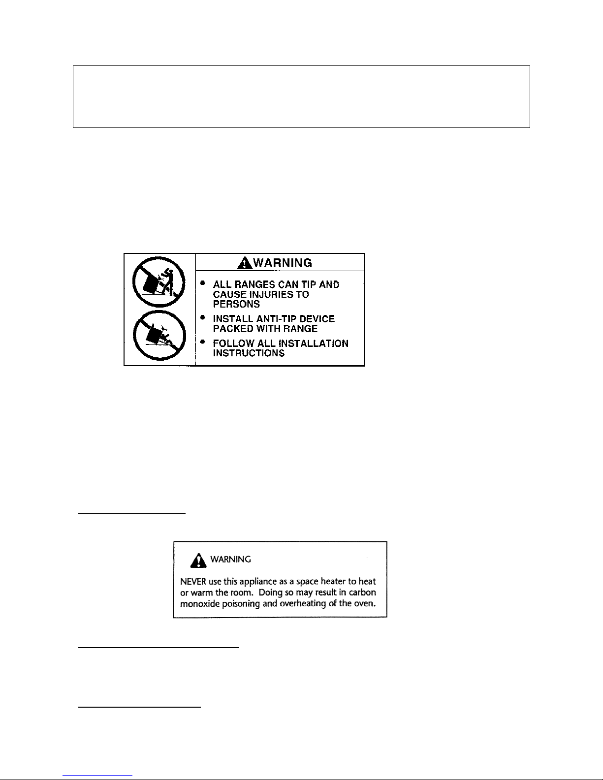
Warning:
To reduce risk of tipping of the appliance from abnormal usage or
by excessive loading of the oven door, the appliance must be secured by a
properly installed anti-tip device. To check if the device is installed properly,
remove lower storage drawer and look beneath the lower frame sheet at the
back area, and verify that the anti-tip device plate is properly engaged in the
rear cover slot just above the frame sheet. You should check this anytime the
range has been moved.
Proper installation. Be sure your appliance is properly installed and grounded
by a qualified technician.
Do not leave children alone. Children should not be left alone or unattended
in area where appliance is in use. They should never be allowed to sit or
stand on any part of the appliance.
Wear proper apparel. Loose fitting or hanging garments should never be worn
while using the appliance.
3 9880023200-CU 36P NEUTRO 120312
User servicing. Do not repair or replace any part of the appliance unless
specifically recommended in the manual. All other servicing should be
referred to a qualified technician.
Storage in or on appliance. Flammable materials should not be stored in an
oven or near surface units.
Do not use water on grease fires. Smother fire or flame by using dry chemical
or foam-type extinguisher.
Use only dry potholders. Moist or damp potholders on hot surfaces may result
in burns from steam. Do not let potholder touch heating elements. Do not use
a towel or other bulky cloth.
Use proper pan size. This appliance is equipped with one or more surface
units of different size. Select utensils having flat bottoms large enough to
cover the surface unit gas burner. The use of undersized utensils will expose
flame out of the pot bottom to direct contact and may result in ignition of
clothing. Proper relationship of utensil to burner will also improve efficiency.
Never leave surface units unattended at high heat settings. Boil-over causes
smoking and greasy spill-over that may ignite.
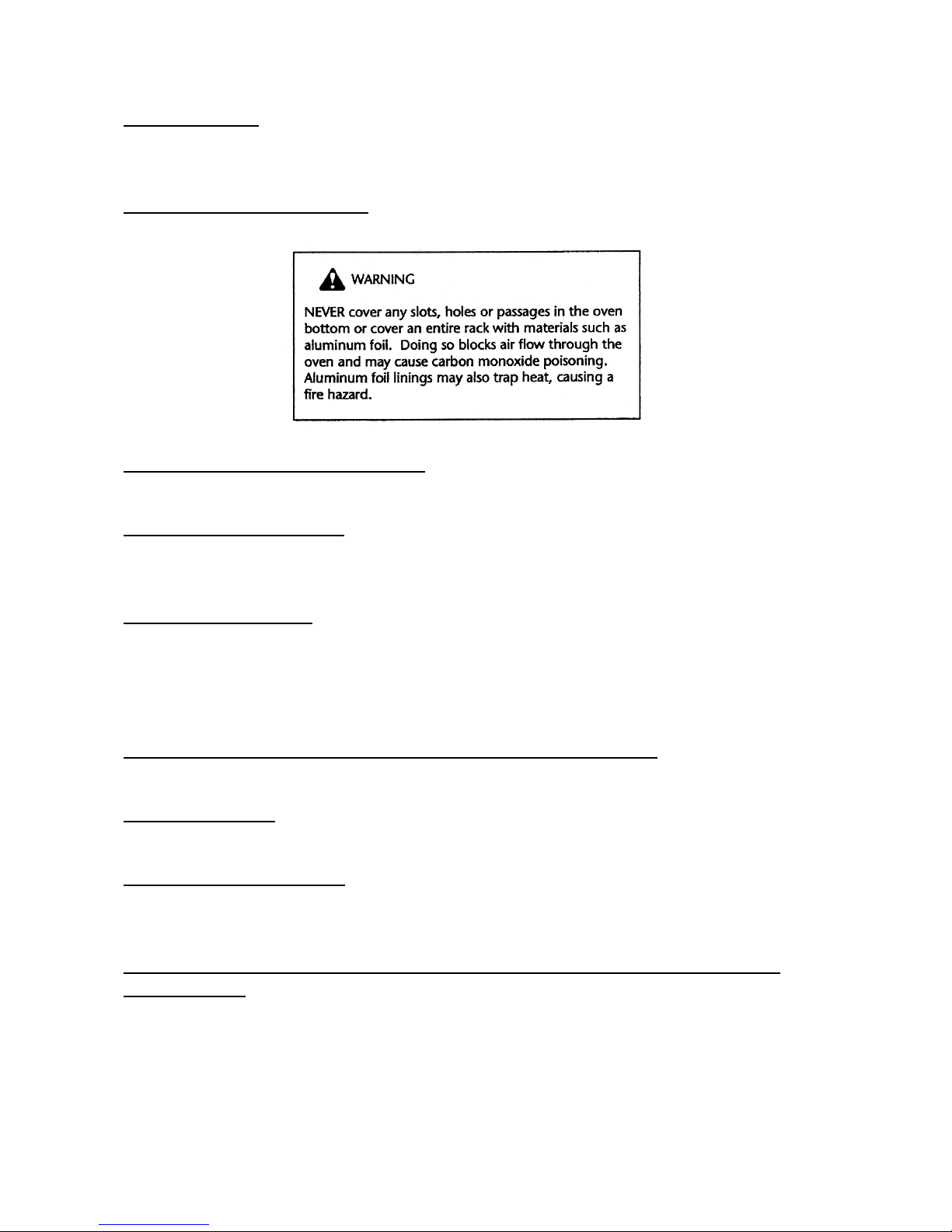
Protective liners. Do not use aluminium foil to line surface unit drip areas and
oven bottoms.
Glazed cooking utensils. Only certain types of glass, glass/ceramic, ceramic,
earthenware, or other glaze utensils are suitable for cooking range use
without breaking due to the sudden change in temperature.
Utensil handles should be turned inward and not extended over adjacent
surface units. To reduce the risk of burns, ignition of flammable materials, and
spillage due to unintentional contact with the utensil, the handle of a utensil
should be positioned so that it is turned inward, and does not extend over
adjacent surface units.

4 9880023200-CU 36P NEUTRO 120312
Do not touch surface units or areas near units as well as oven gas burner or
interior oven surface. Surface units and oven gas burners may be hot even
though they have no flame. Areas near surface units and interior oven
surfaces may become hot enough to cause burns. Make sure hot areas have
had sufficient time to cool, before touching them.
Use care when opening door. Let hot air or steam escape before removing or
replacing food.
Do not heat unopened food containers. Build-up of pressure may cause
container to burst and result in injury. Keep oven vent ducts unobstructed.
Placement of oven racks. Always place oven racks in desired location while
oven is cool. If rack must be moved while oven is hot, do not let potholder
contact hot heating element in oven.
Clean ventilating hoods frequently. Grease should not be allowed to
accumulate on hood and hood filter. (When a cooking hood is installed with
appliance).
When flaming food under the hood, turn the fan off. The fan, if operating, may
spread the flame. (When a cooking hood is installed with appliance).
Do not misuse the appliance door. Misuse of the appliance door can cause
possible hazards or injuries which may result from stepping, leaning or sitting
on it.
CAUTION:
Do not store items of interest to children in cabinets above a
range or on the backguard of a range, children climbing on the range to reach
items could be seriously injured.
■INSTRUCTION GUIDE FOR GAS RANGETOP ■
■RANGETOP GAS BURNER IGNITION AND REGULATION
MOD: Oven Gas Range – Oven Dual Fuel Range
For models with single action automatic ignition, place a pan on the burner
grate. Push in and turn the knob counter clockwise to the LIGHT-HIGH
setting. A clicking sound will be heard and the burner will light, fig. 02. (Only
the desired burner igniter will spark when the control knob is turned to the
LIGHT-HIGH position). After the burner lights, turn the knob to the desired
flame size.

5 9880023200-CU 36P NEUTRO 120312
In case of power failure, hold a lit match to the desired burner head. Push in
and turn the knob counter clockwise to the LIGHT-HIGH setting. After the
burner lights, turn the knob to the desired flame size.
Caution: When lighting the burner, be sure all of the controls are in the OFF
position. Strike the match first and hold it in position before turning to knob to
LIGHT-HIGH.
■INSTRUCTION GUIDE FOR GAS OVEN ■
■INSTRUCTION GUIDE FOR GAS OVEN, CONTROL FEATURES.
MOD: Oven Gas Range
OVEN GAS BURNER IGNITION, REGULATION AND THERMOSTAT
Open the oven door completely, and then push in and turn the thermostat
knob counter clockwise to 500 °F setting. See fig. 03 and 04. A clicking sound
will be heard and the burner will light. Look through orifice “F” for burner
ignition. Keep pushing knob to allow thermocouple of the safety device to
warm up enough, for a period of approx. 5 seconds. Then release the knob
and verify the flame stays on. Turn to desired temperature setting.
Attention: When using the gas burner for the first time, or after a long non
working period, the burner may not ignite at once, so try again until gas
comes out to allow ignition. If problem persists, call an authorized technician
for repair. Note, pre-heat the oven for at least 10 minutes before putting food
in.
GAS BROIL BURNER USE
Set thermostat to Broil mode by turning knob clockwise. See fig. 04.
Follow oven gas burner ignition procedure paragraph. Once broil burner is on,
allow a period of time for preheating the oven cavity before broiling food.
■ELECTRONIC TIMER
MOD: Oven Gas Range
After first electrical power on and in case of any electrical power failure and
power has been restored, the electronic timer will start flashing, fig. Control
Panel VEFSGGL65S.
TO SET TIME OF DAY
Press button. Set time of day with “+” and “-” buttons.
This function remains activated 7 seconds after the last “+” / “-” operation.

6 9880023200-CU 36P NEUTRO 120312
TO CHANGE TIME OF DAY
Press the button for 4 seconds until the hours display will flash.
Change the hours only by using the “+” or “-” button. The minutes and hidden
seconds will not be affected.
TO SET TIMER FUNCTION
This function will be activated with “+” button. Press “+” button again to
increase duration time.
During setting the units are in 10 seconds steps or minutes.
During count down the timer has priority on the display. The bell-symbol
illuminated. The units are in seconds or minutes in the long time section.
The maximum time is 10h. The format change will happen after 99 minutes
and 50 seconds to 1 hour and 40 minutes.
To show time of day press button, after 6 seconds, the count down
comes back on.
TO RESET TIMER
Count down to zero by holding in the “-” button (automatic stop at zero).
SIGNAL
The signal after “time out” will stay on for 7 minutes if it has not been reset
with button. The following signal will be skipped if time of day is
pressed during the last 15 seconds of the timer.
SIGNAL FREQUENCY
If no function is activated, the signal frequency can be selected by pressing
the “-“ button. Three different frequencies are selectable.

7 9880023200-CU 36P NEUTRO 120312
■SELECTOR SWITCH ON GAS OVEN RANGE
MOD: Oven Gas Range
This control allows you to turn on the Oven Internal Light or Oven Forced Air
Convection Fan for cooking or defrosting purposes. See fig. 07.
LIGHT OVEN;
Use this setting to turn on Oven light, light also remains on in all
other modes.
FAN OVEN;
Forced air convection fan or defrost.
Use this setting when Forced air convection is necessary for a
more even cooking finish. Also, use this setting to defrost frozen
food by speeding up air circulation.
■INSTRUCTION GUIDE FOR ELECTRIC OVEN ■
■INSTRUCTION GUIDE FOR ELECTRIC OVEN, CONTROL FEATURES.
MOD: Oven Dual Fuel Range
Note, pre-heat the oven for at least 10 minutes before putting food in.
ON AND OFF PILOT LIGHT
B
Whenever it is on, the oven is electrically powered and functioning, see fig.
Control Panel, page 31
TEMPERATURE PILOT LIGHT
A
It turns on and off to indicate the elements are turning on and off to maintain
the desired oven temperature, see fig. Control Panel, page 31
– MOD. VEFSGEL65.
ELECTRONIC PROGRAMMER
The clock has a maximum setting of Time of day 11h 59 Min. or 23h 59 Min.,
Cooking end time 11h 59 Min. or 23h 59 Min., Minute minder 23h 59 Min.,
and Cooking duration 10h.
Functions:
Cooking duration , Cooking end time , Time of day, Minute
minder , , , Manual selection , Automatic
program
A
.

8 9880023200-CU 36P NEUTRO 120312
Displays:
4-digit 7-segment display for time of day and switching times.
“Dialogue” display to identify condition of timer.
Setting:
Select a function by pressing the function button and set the required time
with and buttons.
+/- Buttons:
Pressing the button increases the time set, pressing decreases it.
The count-up or count-down speed increases the longer the button is held in
the appropriate position.
Setting Time of Day:
Select Time of day function by keeping and buttons pressed together
while setting time of day with and buttons. Any program which has
been set is cancelled and the outputs switched on.
Manual Operation: FOR NON-PROGRAMMABLE OPERATION, THE UNIT
MUST BE IN MANUAL MODE.
Press and buttons together. The relay contacts will switch on. The “A”
symbol will be erased, the cookpot symbol will come on. Any program
which has been set is cancelled.
Semi-Automatic Operation with cooking duration:
Select function and set required end time with the and button.
The “A” and cookpot symbols appear. The relay output becomes active.
If time of day = cooking end time the relay output and the cookpot symbol are
switched off. The audible signal sounds and “A” blinks.
Fully Automatic Operation:
Select function and set required duration with the and button.
The “A” symbol appears. The relay is switched on and the cookpot symbol
appears. Then select function and the earliest possible end time is
displayed. Set the required end time with the and button. The relay and
the cookpot symbol are switched off. The cookpot symbol appears again
when time of day = the calculated start time. At this point you can put the food
in the cooking chamber, set desired oven function and cooking temperature.
After the automatic program has ended, the symbol “A” blinks. The audible
signal is heard and the cookpot symbol and the relay are switched off.

9 9880023200-CU 36P NEUTRO 120312
Minute Minder:
Select button and set required time with and button. As the time
set elapses the bell symbol is displayed. After the time set has elapsed, the
audible signal sounds.
Audible Signal:
The audible signal (1 Hz interval) sounds at the end of a minute minder cycle
or of a cooking program for a period of 7 minutes. The signal can be
cancelled by pressing any function button. Pressing the button without
having previously selecting a function will change the frequency signal.
A selection from 3 possibilities can be made. The selected signal is audible
as long as the button is pressed.
Program Start and Verification:
A program which has been set is carried out after setting the time required.
The “time-to-turn” can be verified at any time by selecting the appropriate
function.
Setting Error Identification:
The setting is incorrect if time of day is in between the calculated cooking
start and end times. If an error has been made, this will be indicated by the
audible signal and by the symbol “A” flashing. The faulty setting can be
corrected by changing one or both functions.
Cancelling a Program:
A program can be cancelled by selecting the manual function. After a
programme which has been set comes to an end, it is automatically
cancelled.
■SELECTOR SWITCH ELECTRIC OVENS
MOD: Oven Dual Fuel Range
This control allows you to choose the desired Oven function mode. The
following illustration gives an overview of what happens in the oven with each
mode setting. It also explains which elements heat up for each specific mode.
The lower and circular elements are concealed under the floor and behind
back wall of the oven respectively. The elements will turn on and off to
maintain the oven temperature.

10 9880023200-CU 36P NEUTRO 120312
ROAST
Use this setting for standard roasting. The bottom
and top elements heat up the air.
BAKE
Use this setting for bottom baking. This intensive heat is best for
cooking less tender meats.
CONVECTION ROAST
Use this setting for Roasting on one rack. The bottom
and top elements heat up. For even heating and faster cooking
with circulation assisted air by the convection fan. The result is a
drier, crisper exterior that seals in the interior juices. It is perfect
for roasting tender meats in an uncovered low sided pan.
CONVECTION BAKE
Use this setting for soft and more even bottom baking. This
intensive heat is best for baking less tender meats.
CONVECTION BROIL
Use this setting to combine the intense heat from the inner top
element with the circulation assisted by the convection fan. This
air circulation crisps the exterior surface and retains inner
moisture in thick cuts of meat.
■BROIL USE
MOD: Oven Dual Fuel Range
Set selector switch to Broiling mode and turn the thermostat knob to
maximum temperature. Allow a period of time for preheating the oven cavity
before broiling food. Always broil with oven door opened and for a maximum
cooking time of 15 minutes.
■RACK PLACEMENT FOR SPECIFIC FOODS
MOD: Oven Gas Range – Oven Dual Fuel Range
Always place oven racks in desired location while oven is cool. If rack must
be moved while oven is hot, do not let potholder contact hot heating element
in oven.

11 9880023200-CU 36P NEUTRO 120312
■GENERAL NOTES
MOD: Oven Gas Range – Oven Dual Fuel Range
CAUTION
1) Do not store or use gasoline or other flammable vapours, liquids
or items in the vicinity of this or any other appliance.
2) Never use appliance as a space heater to heat or warm a room.
3) Do not obstruct the flow of combustion and ventilation air by blocking the
room vents or air intakes. Restriction of air flow to the gas appliance prevents
proper performance and increases carbon monoxide emission to unsafe
levels.
4) Continuous use of the appliance may need extra ventilation, this can be
solved by just opening a window or increasing exhaust power of a cooking
hood.
5) If flame should go out during operation, turn the burner off. If a strong gas
order is detected, open a window and wait five minutes before relighting the
burner.
6) Be sure all control knobs are set in the OFF position prior to supplying gas
to the range.
COOKWARE
To achieve optimum surface cooking performance, select heavy gauge, flat,
smooth bottom pans that conform to the diameter of the cooking area as well
as straight sides.
Pan size should match the size of the cooking area. Pan should not extend
more that 2” beyond the cooking area on gas cooking surface.
Proper pans will reduce cooking times, use less energy and cook food more
evenly.
Remember to use pans with flat bottoms and handles that are easily grasped
and stay cool. To minimize burns, ignition of flammable materials and spillage
due to unintentional contact with the utensil, do not extend handles over
adjacent surface burners. Always turn pan handles toward the side or back of
the appliance, not out into the room where they are easily hit or reached by
children.
NOTES FOR COOKWARE ON GAS BURNERS
We recommend the following pan size per each type of burner, fig. 08:
BURNER TYPE
COOKING PAN BOTTOM SIZE
Power Med (14000 BTU) - on VEFSGGL/GEL65 from 6 to 8 in Ø
Power Larg (17000 BTU) - on VEFSGGL/GEL65 from 8 to 12 in Ø
U-Power (18500 BTU) - on VEFSGGL/GEL65 from 8 to 12 in Ø

12 9880023200-CU 36P NEUTRO 120312
Burner operational Notes, fig. 08A:
-A properly adjusted burner with clean ports will light within a few seconds.
If using natural gas the flame will be blue with a deeper blue inner cone.
-If the burner flame is yellow or is noisy the air/gas mixture maybe incorrect.
Contact a service technician to adjust.
-With LP gas, some yellow tips on the flames are acceptable. This is
normal and adjustment is not necessary.
-If soot is noticed on pan bottom, contact a service technician to adjust.
-If the control knob is turned very quickly from HIGH to LOW, the flame may
go out, particularly if the burner is cold. If this occurs, turn the knob to the
OFF position, wait several seconds and relight the burner. Refer to LOW
SETTING VALVE ADJUSTMENT chapter to adjust LOW setting, if
needed.
-The flame should not extend beyond the edge of the pan, fig. 08B .
■MAINTENANCE
MOD: Oven Gas Range – Oven Dual Fuel Range
CLEANING SAFETY
Turn off all controls and wait for appliance parts to cool before touching or
cleaning them. Do not touch the burner grates, oven inner surface or
surrounding areas until they have had sufficient time to cool.
Clean appliance with caution. Use care to avoid steam burns if a wet sponge
or cloth is used to wipe spills on a hot surface. Some cleaners can produce
noxious fumes if applied to a hot surface.
RANGETOP GAS BURNERS
Take off the removable parts and put them in soapy warm water for 10
minutes. Stubborn soils can be removed by using a
nonabrasive pad or a plastic scouring pad, then rinse making sure that
all openings are free of dirt, fig. 09.
ATTENTION: After cleaning the burner cap, on top surface gas burners,
make sure to place the burner cap in the right position, figure 10.
SURFACE AND OVEN COOKING CAVITY CLEANING
This is easily done using a damp cloth and a non-abrasive detergent,
wipe using a soft dry cloth. For stainless steel parts with stubborn soils, use
only plastic scrubbing pad or a sponge with vinegar and warm water.
Because of many new cleaning products introduced in the marketplace each
year, it is not possible to list all products that can be safely be used to clean
this appliance. Read carefully the cleaner manufacturer’s instructions to be
sure the cleaner can be safely used on this appliance.

13 9880023200-CU 36P NEUTRO 120312
Although, to determine if a cleaning product is safe, test a small
inconspicuous area using a very light pressure to see if the surface may
scratch or discolour. This is particularly important for porcelain enamel, highly
polished, shiny, painted or plastic surfaces.
ABNORMAL OPERATION
Any of the following are considered to be abnormal operation and servicing is
required. Do not use the appliance under these conditions:
- Burner flame with yellow tips.
- Soot on pan bottom.
- Difficult burner ignition.
- Burners fail to remain lit.
- Burner will flame out.
- Difficulty on turning gas valves.
- “Fan” Red Light
C
on control panel lighted, it means Cooling Fan not
working. See fig. Control Panel, page 31, VEFSGEL65S and VEFSGGL65S
NOTES:
Control regularly the correct functioning of Top Surface gas valves, oven gas
thermostat and selector switch.
In case of abnormal functioning of these devices, you must immediately
call a qualified technical assistance service.
■OVEN DOOR
MOD: Oven Gas Range – Oven Dual Fuel Range
TO REMOVE OVEN DOOR
1) Fully open the oven door.
2) Insert a metal Locking Pin (B) in the Locking Hole (A) on each of the
hinges, see figure 11.
3) Grasp the door by the sides toward the back. Raise the front of the door a
few inches and make sure the Locking Pin (B) is locked by the door hinge.
This will prevent the hinge from snapping closed when the door is
removed. (There will be some spring resistance to overcome because of
the hinge being locked). When the front of the door is high enough and
hinges are locked, you will be able to lift the hinges to clear the slots
4) Pull the hinges out of the slots in the oven front frame.

14 9880023200-CU 36P NEUTRO 120312
TO REPLACE THE OVEN DOOR
1) Grasp the sides of the door at the center and insert the ends of the hinges
and fix hinge slots in the oven front frame.
2) With the door open all the way, pull-out the two Locking Pins (B) from the
hinge Locking Holes(A).
3) Raise the oven door and make sure that it fits evenly with the front sides.
WARNING:
Never take out the Locking Pins while the door is off. Do not close
the hinges without the weight of the door, the powerful springs will snap the
hinges closed with great force.
CAUTION:
Do not place excessive weight on or stand on an open oven door.
This could cause the range to tip over, break the door, or injure the user.
Also, do not attempt to open or close door or operate oven until door is
properly replaced.
■REPLACING THE OVEN LIGHT
MOD: Oven Gas Range – Oven Dual Fuel Range
WARNING:
To prevent electrical shock and or personal injury:
1) Before replacing the light bulb, be sure the electric power is turned off at
the circuit breaker.
2) Do not operate the oven unless the light cover is securely in position.
3) Be sure the oven and light bulb are cool.
4) Do not touch hot bulb with a damp cloth as this may cause the bulb to
break.
5) If the light cover is damaged or broken, do not use the oven until a new
cover is in place.
To replace oven light bulb:
1) Before replacing light bulb, disconnect oven electric circuit.
2) Remove oven racks.
3) Remove, unscrewing, lens bulb cover and light bulb.
4) Replace bulb with a 25 W – 120 Vac appliance bulb only.
5) Replace lens bulb cover.
6) Reconnect power to range. Reset electronic clock.

15 9880023200-CU 36P NEUTRO 120312
■INSTALLATION INSTRUCTIONS
MOD: Oven Gas Range – Oven Dual Fuel Range
SPECIAL WARNING:
ONLY QUALIFIED AND AUTHORIZED PERSONNEL MUST INSTALL OR
SERVICE THIS RANGE.
READ “SAFETY INSTRUCTIONS” IN THIS BOOK BEFORE USING
RANGE.
IMPROPER INSTALLATION, ADJUSTMENT, ALTERATION, SERVICE,
MAINTENANCE OR USE OF RANGE CAN RESULT IN SERIOUS INJURY
OR PROPERTY DAMAGE, AND SO THE MANUFACTURER WILL NOT BE
RESPONSIBLE.
This appliance must be installed in accordance with the manufacturer’s
installation instructions and local codes or, in the absence of local codes, with
the National Fuel Gas Code, ANSI Z223.1 / NFPA 54 in the U.S.A., and
current CAN/CSA B149.1 Natural Gas and Propane Installation Code.
CLEARANCE DIMENSIONS
Range may be installed with zero inches clearance adjacent to (against)
combustible construction at the rear and on the sides below the rangetop. For
complete information in regard to the installation of wall cabinets above the
range and clearances to combustible wall above the cooking top see the
installation drawing fig. n°12 and 13. For Safety considerations do not install
a range in any combustible cabinetry which is not in accord with the
installation drawings.
NOTE:
42 inch dimension between cooking top and wall cabinet shown on
illustration fig. n°13 does not apply to ranges with an elevated oven. The “A”
42 inch dimension may be reduced to not less than 36 inches when the wall
cabinets in a domestic home are protected with fireproof materials in
accordance with American National Standards – National Fuel Gas Code. “B”
has to be not less than 8 inch from the top surface to a vertical side
combustible wall.
The “C” dimension is the total of product’s width plus 1”.
To eliminate the risk of burns or fire by reaching over heated surface units,
cabinet storage space located above the surface units should be avoided.
If cabinet storage is to be provided, the risk can be reduced by installing a
range hood that projects horizontally a minimum of 5 inches beyond the
bottom of the cabinets.

16 9880023200-CU 36P NEUTRO 120312
CAUTION: SOME CABINETS AND BUILDING MATERIALS ARE NOT
DESIGNED TO WITHSTAND THE HEAT PRODUCED BY THE NORMAL
SAFE OPERATION OF A LISTED APPLIANCE. DISCOLORATION OR
DAMAGE, SUCH AS DELAMINATION, MAY OCCUR.
LOCATING THE RANGE
Do not set range over holes in the floor or other locations where it may be
subject to strong drafts. Any opening in the wall behind the range and in the
floor under the range should be sealed. Make sure the flow of combustion or
ventilation air is not obstructed.
NOTE
:A range should not be installed over kitchen carpeting.
VENTILATION
Ventilation must be in accordance with local installation code. The appliance
must be installed in a well-ventilated environment to guarantee a correct
combustion gases exchange, proper air circulation and working temperature
within safety limits.
MODEL NUMBER PLATE
The Model Number Plate is located in front oven surface, on right side. A
second Model Number Plate is applied on the front page of the instruction
booklet.
■ANTI-TIP DEVICE INSTALLATION INSTRUCTIONS
MOD: Oven Gas Range – Oven Dual Fuel Range
NOTE:
A risk of range tip over exists if the appliance is not installed in
accordance with the installation instructions provided. The proper use of this
device minimises the risk of TIPPING-OVER . In using this device the
consumer must still observe the safety precautions as stated in the Instruction
Manual and avoid using the oven door and/or lower drawer as a step stool.
Installation instructions are provided for wood and cement wall. Any other
type of construction may require special installation techniques as deemed
necessary to provide adequate fastening of the ANTI-TIP bracket to the wall.
STEP 1 – Locating The Bracket (see fig. 14)
A. Mark the wall from either the right or left rear “EDGE” of the range is to be
located.
B. Place the Anti-Tip Bracket 8 5/8” from the marked “EDGE” toward centre
of opening and against the back wall with a first hole height of 1 ¾” plus
“A” (distance between side wall bottom edge and floor after range
leveling) as shown in figure 14.

17 9880023200-CU 36P NEUTRO 120312
C. Use the bracket as a template and mark the required holes, as shown in
figure 14, for the type of construction you will be using.
STEP 2 – Anti-Tip Bracket Installation
Locate the center of the two holes to be drilled on the wall. Drill a 1/8” pilot
hole in the centre of each hole. (A nail or awl may be used if a drill is not
available). On Wood Construction Wall secure the Anti-Tip bracket to the wall
with the two 3/8” x 1 ½” self-drilling screws provided, and on Cement or
Concrete Construction Wall secure the Anti-Tip bracket to the wall by drilling
two holes with a 4/8” drilling bit and using the two 3/8” x 1 ½” wall plugs with
screw.
NOTE:
Be aware of not drilling the wall hole in proximity of steel pipes or other
components inside the wall that may be damaged. As shown in figure 14 you
have two slots in the rear cover to choose from. Also, use a minimum of 2
screws to install bracket to the wall.
STEP 3 – Range Installation
A. Align the range to its designated location and slide it back into position.
Make sure that the Anti-Tip bracket plate is fully inserted into the range
rear cover slot and above the lower frame plate.
B. For Safety Considerations as well as optimum performance adjust the
range so it is level. This may be checked by placing a spirit level or a large
pan of water on the rangetop or on the oven rack. If an adjustment is
required on free standing, pull the range forward, tip the range and rotate
the levelling feet as required. Slide-in ranges require total removal from
cabinet before an adjustment can be made.
C. To check the range for proper installation of the anti-tip bracket: Remove
lower name-tag cover or foot cover, by unscrewing its four fixing screws.
Use a flashlight and look beneath lower frame plate and verify that the
anti-tip device horizontal side is properly engaged in the rear cover slot
and just above the lower frame plate.
D. Proceed with the reminder of the installation instructions as well as proper
range four legs installation, see please fig. 14A.

18 9880023200-CU 36P NEUTRO 120312
■CONNECTING THE RANGE
MOD: Oven Gas Range – Oven Dual Fuel Range
ELECTRICAL SUPPLY
The appliance, when installed, must be electrically grounded in accordance
with local codes or, in absence of local codes, with National Electrical Code,
ANSI/NFPA 70
In Canada the appliance must be installed in accordance with the current
CSA Standard C22.1 - Canadian Electrical Code part 1.
IMPORTANT:
The appliance must only be installed by a qualified and
specialized electrician.
ELECTRICAL INSTALLATION FOR RANGE WITH GAS OVEN
MOD: Oven Gas Range
This appliance is equipped with a three-prong grounding plug, which must be
plugged directly into a properly grounded three-hole single-phase 120 VAC
60 Hz 15 amps electrical outlet.
NOTE:
House wiring and fusing must comply with local codes. If no local
codes are applicable, wire in accordance with the National Electrical Code,
ANSI/NFPA 70 latest edition.
The three-prong grounding plug offers protection against shock hazards. DO
NOT CUT OR REMOVE THE THIRD GROUNDING PRONG FROM THE
POWER CORD PLUG.
If an ungrounded, two-hole or other type of electrical outlet is encountered, it
is the personal responsibility of the appliance owner to have the outlet
replaced with a properly grounded three-hole electrical outlet.
The cable cord connected to the appliance is a flexible type of cable. Pass it
through hole prepare in cabinet to plug it to wall socket.
To facilitate service, the flex cable must not be shortened and should be
routed to permit temporary removal of the appliance.
■ELECTRICAL INSTALLATION FOR RANGE WITH ELECTRIC OVEN
MOD: Oven Dual Fuel Range
The Range can be installed either with a double-phase 120/240V ~ 60 Hz for
Canada and 120/208V ~ 60 Hz for US, use flexible cord type according with
National Codes. CAUTION: Be sure the electrical power is off from the
breaker box to the junction box until the range is installed and ready to
operate.

19 9880023200-CU 36P NEUTRO 120312
In case of a fixed connection to junction box, a 1/8” open gap two way switch
must be used before the Junction Box.
NOTE:
Install a suitable flexible cord, through Junction Box on rear of
appliance, to oven electrical terminal block. Follow fig. 15A and fig. 15B for
proper electrical connection of flexible cord to appliance terminal block.
Attention: always refer to product label for correct electrical power rate, before
proceeding with electrical connection.
ELECTRICAL CONNECTION ON TERMINAL BLOCK
1. For Double phase connection 120/240V~ 60 Hz for Canada, fig. 15A;
On position n°1, connect the Black electrical supply wire (hot wire or L1),
position n°2, connect the Red electrical supply wire (hot wire or L2),
position n°3, connect the White electrical supply wire (neutral wire or N),
to position , connect the Green ground electrical supply wire (ground
wire or E)
2. For Double phase connection 120/208V~ 60 Hz for US, fig. 15B;
On position n°1, connect the Black electrical supply wire (hot wire or L1),
position n°2, connect the Red electrical supply wire (hot wire or L2),
position n°3, connect the White electrical supply wire (neutral wire or N),
to position , connect the Green ground electrical supply wire (ground
wire or E)
CAUTION:
The flexible cord must be held tight by the cord lock, in such a way that it may
not be pulled out. The flexible cord path must not be in proximity or in contact
with hot surfaces that may damage the cord itself.
GROUNDING
IMPORTANT
: Local codes might vary, installation, electrical connections and
grounding must comply with all applicable local codes.
WARNING: This appliance requires a ground connection for your protection
against shock hazard and should be connected directly into a properly
grounded receptacle.

20 9880023200-CU 36P NEUTRO 120312
WARNING: DISCONNECT ELECTRICAL SUPPLY BEFORE
SERVICING THE APPLIANCE.
When the flexible cord has to be changed it is necessary to follow
the procedure hereafter described:
-Turn off main gas shut-off valve and disconnect electrical supply
-Pull out entire range from the counter.
-Disconnect gas supply connector from appliance gas manifold
-Open up connecting terminal block cover.
-Open flexible cord lock and loosen up old cord prongs from terminal block
-Connect new flexible cord prongs to terminal block and fix flexible cord lock,
remember earth wire, Green, must be longer by one inch that the other ones.
For Line and Neutral wire connection, follow signs on terminal block.
-The flexible cord must be held tight by the cord lock, in such a way that it
may not pulled out. The flexible cord path must not be in proximity or in
contact with hot surfaces that may damage the cord itself.
ATTENTION: the flexible cord must be in accordance with National
Electrical Codes and suitable for the Range technical characteristics
electrical ratings. A 18 AWG three-prong grounding plug flexible cord,
type SJT 3x18 AWG for the gas oven range only. Use a suitable prong
grounding plug flexible cord, type SJT for the electric oven range
according to the type of electrical system available.
THE MANUFACTURER DECLINE ANY RESPONSIBILITY FOR
IMPROPER INSTALLATION, ADJUSTMENT, ALTERATION, SERVICE,
MAINTENANCE OR USE OF RANGE WHICH CAN RESULT IN SERIOUS
INJURY OR PROPERTY DAMAGE.
■GAS SUPPLY
MOD: Oven Gas Range – Oven Dual Fuel Range
Installation of this range must conform with local codes or, in the absence of
local codes, with the National Fuel Gas Code, ANSI Z223.1 latest edition.
In Canada the range must be installed in accordance with the current CGA
Standard CAN/CGA-B149 – Installation Codes for Gas Burning Appliances
and Equipment and/or local codes.
GAS SUPPLY CONNECTION: (SEE FIGURE 17B)
A TRAINED SERVICEMAN OR GAS APPLIANCE INSTALLER MUST
MAKE THE GAS SUPPLY CONNECTION. Leak testing of the appliance
shall be conducted by the installer according to the instructions given
in section (h).
Table of contents
Popular Range manuals by other brands

Brada Appliances
Brada Appliances BRADA CREF366FCB Use & care manual

Jenn-Air
Jenn-Air JDS9860CDW01 installation instructions

Whirlpool
Whirlpool 30 " Eye-Level Gas Range installation manual

Frigidaire
Frigidaire CMEF212ES3 Use & care manual

GE
GE 164D2966P079 Use and care guide

Kenmore
Kenmore 665.75032 Use & care guide


Frigidaire
Frigidaire 316417119 Use & care manual

German pool
German pool GP11-2 user manual

Range Master
Range Master Professional+ 90 Gas User's guide & installation instructions

Range Master
Range Master Classic Deluxe 100 Dual Fuel User's guide & installation instructions

Southbend
Southbend 448EE-4G/T Specification sheet

Bertos
Bertos PLUS 600 Series instruction manual